Design of variable-rate liquid fertilization control system and its stability
analysis
Jicheng Zhang
1,
Shouyin Hou
2,
Runtao Wang
1,
Wenyi Ji
2,
Ping Zheng
1,
Shi Wei
3*(1. College of Electrical and Information, Northeast Agricultural University, Harbin 150030, China; 2. Engineering College, Northeast Agricultural University, Harbin 150030, China; 3. College of Agriculture, Northeast Agricultural University, Harbin 150030, China)
Abstract: Variable-rate technology (VRT) has been paid more attentions by farmers in an attempt to match inputs to local growing conditions efficiently. Farmers in every country are highly encouraged to adopt this practice rather than uniform-rate application (URA). However, the standard methods and design used to quantify application accuracy for VRT remain lacking. Therefore, a variable-rate liquid fertilization control system was designed to meet accurate fertilization demand. The designed control system could enable the real-time proportion and mixture of three kinds of liquid fertilizers, namely, N, P and K, in accordance with decision support subsystem. The task controller reads related information and sends such data to the control system, which is responsible for fertilization operation. The controller could realize liquid fertilizer adjusting through the electromagnetic flow control valves. A high-precision flow meter could measure the fertilization amount, which is sent as feedback to the controller to form a closed-loop control system based on the improved proportional-integral-derivative (PID) control algorithm that could enhance the stability and accuracy of precision variable-rate liquid fertilization control systems. Comparisons between the actual and planned application rates indicated good performance for both static and field experimental trials. Mathematical models and transfer functions for some functional modules were then constructed by classical theories to derive a system characteristic equation. To verify the static and dynamic performances, the control system was simulated using the Simulink module on Matlab. Results showed that the variable-rate fertilization was in accordance with the planned data and that the signal trace effect was good. The error was less than 5% for fertilization amount and fertilizer proportion, respectively, and the control response time was 6 s.
Keywords: fertilization control system, variable-rate technology, precision fertilization, closed-loop control system, improved PID control algorithm, Simulink
DOI: 10.25165/j.ijabe.20181101.2583
Citation: Zhang J C, Hou S Y, Wang R T, Ji W Y, Zheng P, Wei S. Design of variable-rate liquid fertilization control system and its stability analysis. Int J Agric & Biol Eng, 2018; 11(1): 109–114.
1 Introduction
A precision agriculture (PA) system or variable-rate application (VRA) system is widely adopted to improve the quality and quantity of crop yields, lower the costs of farming process, and decrease the effects of fertilizer and pesticide application on crops[1]. Precision
agriculture aims to improve yield, quality and benefits for farmers by optimizing agriculture inputs[2,3]. Avoiding excessive
application of fertilizer is one of the important outcomes of precision agriculture. The variable rate fertilization (VRF) technology can improve fertilizer utilization efficiency, and reduce environmental impact[4]. The intention of VRF is to apply specific and precise
fertilizer at different sites to satisfy site-specific management requirements[5-7]. VRA could also be applied to seeds, fertilizers,
Received data: 2016-05-20 Accepted data: 2017-06-12
Biographics: Jicheng Zhang, PhD, Senior Engineer, research interests: agricultural electrification and automation, Email: [email protected];
Shouyin Hou, Engineer, research interests: agricultural machanization, Email: [email protected]; Runtao Wang, Lecturer, research interests: agricultural electrification and automation, Email: [email protected]; Wenyi Ji, Senior Engineer, research interests: agricultural machanization, Email: [email protected]; Ping Zheng, Associate Professor, research interests: agricultural big data analysis, Email: [email protected].
*Corresponding author: Shi Wei, Professor, research interests: high yield and physiology of crops. Northeast Agricultural University, No.59 Mucai Street, Xiangfang District, Harbin 150030, China. Tel/Fax: +86-451-55191748, Email: [email protected].
herbicides and pesticides. This approach is an important management strategy in accordance with agricultural field variability. Therefore, PA is one of the most important revolutions in modern agriculture.
VRA is a method of applying varying rates of inputs in appropriate zones throughout a field. The goals of VRA are to maximize efficiency to its fullest potential in input application, and reduce waste. VRA has undergone a revolution with the advancement in electrical and mechanical engineering[8].
Researches showed that applicator dynamics affects the performance of VRAs[9-12]. In adjusting the rate of inputs on some
predefined or real-time decision support subsystem, electronic controllers and a mechanical drive system are integrated to implement variable-rate technology (VRT). Automatic section control is PA technology that has helped improve application accuracy by reducing overlap[13,14].
A variable-rate liquid fertilization system consists of a geographic information system (GIS)-based fertilizer map, a positioning system model, a task controller for fertilizer rate controller, a communication module, and an implement-ECU for operating variable-rate fertilization by regulating valves[15-17]. The
cost and robustness, an improved proportional-integral-derivative (PID) control algorithm was designed in this study.
PID controller has a simple structure and good robustness, and it is widely used in process control system. PID control algorithm is an important factor that must be considered in VRA system. However, conventional PID controllers cannot achieve good performance for time-varying objects and non-linear systems. Therefore, several methods of conventional and improved PID control are studied systematically and deeply nowadays. By tuning the three parameters in PID controller algorithm, the controller can provide control action designed for specific process requirements. The response of the controller can be described in terms of the responsiveness of the controller to an error, the degree to which the controller overshoots the setpoint, and the degree of system oscillation. The hysteresis piecewise integral function designed in this study could make up large deviation defects in a short time in the process of start and end or greatly increasing and decreasing set, but it could also shorten the system adjusting time to realize high stability, fast response, and strong reliability.
GIS interpolation techniques have been successfully used to calculate the application variation of fertilizer spreaders accurately in modern agricultural production[18,19] along with a positioning
system model. The controller could measure vehicle locations accurately by GIS and positioning signal in the field[20-22]. The
variable-rate fertilization control system could calculate the planned fertilizer amount according to variation in flow, kg/s; forward speed, m/s; or disc speed, r/min; and send variable-rate fertilizing signal to operation structure[23].
This study developed a variable-rate fertilizer applicator combined with electrical and mechanical engineering, which was applied in the field of northeast China. The VRA operation could improve Chinese agricultural engineering level and obtain a reasonable fertilization effect to reduce production cost and improve environmental quality.
2 Materials and methods
The variable-rate liquid fertilizer applicator consisted of task controller for fertilizer rate control, a communication module, an implement-ECU for operating variable-rate fertilization, a positioning module, and GIS module. The components of VRT fertilizer applicators were properly designed in this research[24].
Due to consideration was paid to the type, characteristics, and method of fertilizer application in the northeast China. The entire unit of VAR fertilizer applicator was mounted on a 4WD prime mover specially designed in common Chinese plantation production. Prior to the fertilizer application, a predefined fertilization map should have been prepared. This map contains the fertilized coordinates and related fertilizer inputs. These data were stored in the hard disc memory of the embedded computer system (host PC). On board, the VRT fertilizer applicator was a dedicated 2 kW generator.
2.1 Control system electrical design
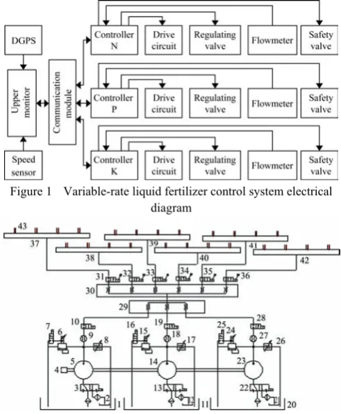
The variable-rate liquid fertilization control system designed in this research focused on the real-time proportion and mixture of three liquid fertilizers, i.e., N, P and K. The electrical diagram is shown in Figure 1. The upper machinery sent fertilizing information in accordance with the predefined decision support system to the control system, which was responsible for fertilizing operation. The operation principle was that the controller could realize liquid fertilizer controlling by changing electromagnetic flow control valve. A high-precision flow meter could measure the
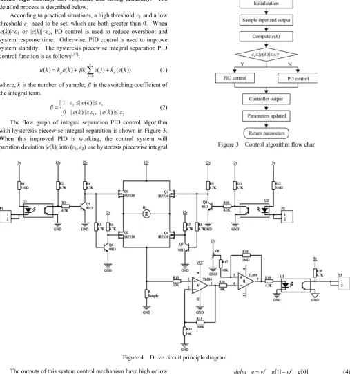
fertilizer amount, which could feedback into the controller. A closed-loop control system that may improve the stability and accuracy to realize precision variable-rate liquid fertilizer could be formed. This research used 24 kW diesel as power source to provide stable energy to the fertilizing pump of N, P, K. To solve the liquid fertilizer mixture uniformity problem, a Z-shaped mixture was designed to be fixed before split-flow valve. The variable fertilizing system layout is shown in Figure 2.
Figure 1 Variable-rate liquid fertilizer control system electrical diagram
1. Liquid N fertilizer storage tank 2. Liquid N fertilizer tank 3, 13, 22. Two- position three-way electromagnetic valve 4. Diesel machine 5. Liquid N spraying pump 6, 15, 24. Electromagnetic relief valve 7, 10, 16, 19, 25, 28. Two-position two-way electromagnetic valve 8, 17, 26. Electromagnetic flow control valve 9, 18, 27. Flow meter 11. Liquid P fertilizer storage tank 12. Liquid K fertilizer tank 14. Liquid P spraying pump 20. Liquid K fertilizer storage tank 21. Liquid K fertilizer tank 23. Liquid K spraying pump 29. Collecting valve 30. Regulating valve 31-36. Two-position two-way manual reversing valve 37-42. Liquid fertilizer 43. Application boom with nozzles
Figure 2 Variable-rated liquid fertilizer system layout
2.2 Hardware and software design
2.2.1 Hardware
This research used STC12C5412AD as control system core processor with high-speed, low-power, and strong anti-interference characteristics, which is suitable for motor control and strong interference. Regulating valve driving circuit uses H-bridge circuit made of MOS pipes that could use optocoupler isolation to reliably turn on and turn off MOS pipes. The drive circuit is shown in Figure 4. P1 and P2 connect with STC12C5412AD two I/Os. Once P1 is high level and P2 is low level, field effect pipes Q2, Q3 work, Q1, Q4 shut down, and the solenoid valves may do relate operation. When P1 is low level and P2 is high level, field effect pipes Q1, Q4 work, Q2, Q3 shut down, and the solenoid valves could also work. However, when P1 and P2 are both high or low level, the solenoid valves will not work.
2.2.2 Software
piecewise integral separation PID control algorithm[25,26]. This
control algorithm could make up large deviation defects in a short time in the process of start and end or greatly increasing and decreasing set, but it could also shorten the system adjusting time to realize high stability, fast response, and strong reliability. The detailed process is described below.
According to practical situations, a high threshold ε1 and a low
threshold ε2 need to be set, which are both greater than 0. When
|e(k)|>ε1 or |e(k)|<ε2, PD control is used to reduce overshoot and
system response time. Otherwise, PID control is used to improve system stability. The hysteresis piecewise integral separation PID control function is as follows[27]:
0
( ) p ( ) i k ( ) d( ( ))
j
u k k e k βk e j k e k =
= +
∑
+ (1)where, k is the number of sample; β is the switching coefficient of the integral term.
2 1
1 2
1 | ( ) | 0 | ( ) | , | ( ) |
ε e k ε
β
e k ε e k ε
≤ ≤
⎧
= ⎨ ≥ ≤
⎩ (2)
The flow graph of integral separation PID control algorithm with hysteresis piecewise integral separation is shown in Figure 3. When this improved PID is working, the control system will partition deviation |e(k)| into (ε1,ε2) use hysteresis piecewise integral
separation. Different integral intensity could be applied according to deviation absolute value.
Figure 3 Control algorithm flow char
Figure 4 Drive circuit principle diagram The outputs of this system control mechanism have high or low
levels, and with turn on and turn off information. This could improve system anti-interference ability. The controllers can change fertilizing amount by controlling high or low level time. The flowmeters monitor real-time fertilizing amount to feedback by pulsing signals. Then controllers could record pulsing signals to calculate fertilizing amount indirectly. The hysteresis piecewise integral function is:
Deviation:
_ _ _ [0]
e vf =vf std vf g− (3) One-order deviation:
_ _ [1] _ [0]
delta e vf g= −vf g (4) Two-order deviation:
2 _ 2 _ [1] _ [2] _ [0]
delta e= ×vf g −vf g −vf g (5) Above all, system control function:
( ) p _ i 2 _ d _
u k =k e vf +βk delta e k delta e+ (6) where, kp is the proportion coefficient; ki is the integral coefficient;
kd is the differential coefficient; β is the integral term coefficient;
vf_std is the flow standard value, L/min; vf_g[i] is ith time
Figure 5 Control system principal flow diagram
2.3 Experimental test
2.3.1 Static test
Static test was designed in an agricultural engineering laboratory. The test comprised liquid fertilizer tanks and their brackets, diaphragm fertilization pumps and their brackets, diesel engine, BC44BRL-24-03D electrical regulating value, TS-800-F pressure transmitters, solenoid valve, liquid fertilizer mixing and sharing devices, 801 flowmeter, and cylinder components.
First set the flow of N, P, and K liquid fertilizers manually. According to Figure 2, 24 fertilizer nozzles were divided equally into six groups. This static test (Table 1) chose one nozzle per group randomly, so it could obtain six experimental nozzle data. When the applicator (including 24 nozzles) worked in t min, the total flow Q1 was set manually. The fertilizer amount Mi
(i=1,2,…,6) flowed from six random nozzles was measured. The flow of all 24 nozzles was calculated as follows:
6 24 ( i1 i) 4
M =
∑
=M × . Thus, the measured flow was as follows:Q=M24/t. The control error was as follows: 1 1
100%
r Q Q E
Q
−
= × .
Table 1 Control system errors and static fertilization experimental data
Parameter Test 1 Test 2 Test 3 Test 4 Test 5 Test 6
Q1/L·min-1 135 135 135 127 127 127 t/s 179.75 177.02 179.24 180.43 178.78 177.72 M1/L 17.68 17.38 17.69 16.52 16.39 16.42 M2/L 17.64 17.41 17.66 16.47 16.41 16.38 M3/L 17.59 17.44 17.57 16.51 16.39 16.40 M4/L 17.62 17.38 17.57 16.50 16.37 16.31 M5/L 17.61 17.39 17.58 16.52 16.43 16.38 M6/L 17.65 17.43 17.65 16.49 16.35 16.34 M24/L 423.16 417.72 422.88 396.04 393.36 392.92 Q/L·min-1 141.05 141.6 141.75 132.01 131.85 133.19
error/% +4.48 +4.89 +4.99 +3.95 +3.82 +4.87
2.3.2 Field test
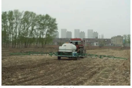
To meet the reliability of dynamic performance tests, this research established a fertilization map on GIS platform for a certain corn field. The variable-rate applicator could calculate the theory of N, P and K fertilizer flow by positioning information, applicator speed, and GIS information, which was programmed by VB 6.0 in host PC. The calculated fertilizer flow data were sent to the control system to fertilization by the serial port. The control system could monitor the variable-rate fertilizer flow by flowmeter and upload to the host computer via the serial port to analyze. The field test is shown in Figure 6. The results in experiments showed that a short time (about 6 s) was needed for the control system to start up stable and reflected that the system dynamic response was good, with high stability and high control accuracy characteristics.
Based on the establishment of closed-loop control system of real-time system pressure sensor and flow sensor, the system could reduce the deviation between the actual output value and the
expected value according to the output change, and realize automatic adaptive adjustment of VRA process.
Figure 6 Field test
3 System stability analysis
3.1 Control system mathematical model establishment
3.1.1 Electronically controlled pressure regulating valve mathematical model
The variable-rate fertilization system is made of a fertilization controller, an electronically controlled pressure regulating valve, monitor feedback components, and so on. The electrically controlled pressure regulating valve is one of the control system execution components. It plays an important role in fertilization system. The deviation equation was designed by the principle of automatic control system structure as follows[28,29]:
( )e t =u to( )−u t( ) (7) where, e(t) is the deviation value; u0(t) is the given value that is
theory fertilizing value; u(t) is the measured value that is truly fertilizing value.
The control system uses PID control algorithm to establish an error regulating equation as follows:
1 ( )
( ) ( ) ( )
a p d
i
de t e t K e t e t dt T
T dt
⎡ ⎤
= ⎢ + + ⎥
⎣
∫
⎦ (8)where, ea(t) is the deviation value after regulating; Kp is the scale
factor; Ti is the integral time constant; Td is the derivative time
constant.
The dynamic equation of electronically controlled pressure regulating valve is as follows:
V ta( )=K e ta a( ) (9) where, Va(t) is the electronically controlled regulating valve input
voltage; Ka is the amplification factor of regulating valve amplifier
circuit.
The transfer function of electrically controlled pressure regulating valve could be obtained by Equation (9) Laplace transform as follows:
( ) 1
( )
( ) 1 1
a
a p d
i E s
G s V s
K K T s
T s
= =
⎛ ⎞
+ +
⎜ ⎟
⎝ ⎠
(10)
3.1.2 Fertilization pump transfer model establishment
The output of fertilization pump is the fertilization amount, and the input is the revolutions per minute. The relationship between input and output can be approximately considered as a first-order system as follows[30,31]:
( ) 1
1
K G s
T
=
+ (11)
The revolutions per minute are a jump function. Substituting Equation (12) into Equation (11) could yield Equation (13) by Laplace transform as follows:
N s( )=K s/ (12)
( ) 250 1 1
t T q t = K ⎛⎜ −Te− ⎞⎟
⎝ ⎠ (13)
Through some field tests, the parameters of this control system are as follows: K1=0.0029, T=0.0001, K =250.
3.2 Stability judgment
This research designed fertilization pump characteristic equations of electronically controlled pressure regulating valve as follows:
2
1( ) a p i d ( a p i i) a p
D s =K K TT s + K K T T s K K+ + (14) D s2( )= +s 10290 (15) Given that each scale factor in engineering applications is positive, each element of the first column in roll list is greater than zero. Therefore, according to Routh criterion, the electronically controlled pressure-regulating valve and fertilization mathematical model of the pump are stable.
3.3 Simulation analysis based on Matlab
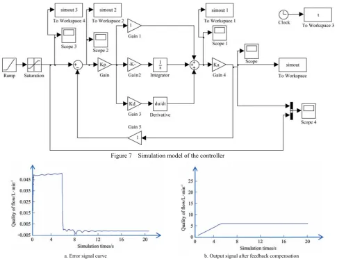
3.3.1 Implement-ECU control system architecture establishment To verify the feasibility of the implement-ECU control system based on the established mathematical model, this research built a simulation model on Matlab Simulink model window[32]. At the
beginning of simulation, theory flow rate would be produced as system input signal. The precise quantitative factors are available to calculate PID controller output. Its scale factor Kp is 1, the
integration constant Ti is 0.01, and the differential constant Td is 0.1.
Each module will be constructed together, as shown in Figure 7. 3.3.2 System response curve analysis
This research set the fertilization rate 5 in Simulink. Figure 8 presents the system response curve. Figure 8a shows the error signal curve of fertilization signal within ±10%; Figure 8b shows the output signals after feedback compensation. As shown by the output in Figure 8b, the response curve is overlap with input, which could reflect that the output signal is satisfied as expected after closed-loop control system. This simulation could show that the control system has anti-interference and small fluctuation characteristics.
Figure 7 Simulation model of the controller
a. Error signal curve b. Output signal after feedback compensation
Figure 8 Controller output signal
4 Conclusions
In this research, we designed a variable-rate liquid fertilization system which could be equipped on high horsepower (257.4-294.1 kW tractor) operation equipment. It could be used on high speed seeding and fertilization machine during sowing periods, and mounted on inter-tillage fertilization spraying machine when
cultivation periods. This technology had gained the Identification of Scientific and Technological Achievements by the State Science and Technology Bureau.
This fertilization system has below characteristics:
error of fertilizer proportion was 5%; the control response time was 6 s.
2) The control principle used the sectional type integral separation PID to realize precision variation, stabilization, and rapid control of the liquid fertilizers.
3) This study analyzed the stability and proved the feasibility of the variable-rate liquid-state fertilization system on the basis of electric-hydraulic proportional velocity regulation valve. To acquire the characteristic equation of the system, a mathematical model of each of the system function module was first established by classical control theory. The transfer function was then listed. The characteristic equation of the system met the requirements of Routh criterion. The course of work was steady.
4) The use of Matlab software in the Simulink module simulated the course of work of the system to understand its static and dynamic performances. Results indicated that the fertilizer fed stabilized within the margin of error. To verify the simulation result, a test was conducted to validate the system. Test results indicated that the system can completely control variable-rate fertilization, and the error of the variable fertilization was less than 0.6 mL in each time. The least precision fertilization of the system was 97%, which can meet the liquid-state fertilizer variable requirements.
[References]
[1] Bowers C G, Roberson G T, Cassel D K, Naderman G C, Brownie C. Variable rate liquid nitrogen application for cotton and corn production. Proceedings of the ASAE Annual Meeting (ASAEAM' 01), 2001; No. 011201.
[2] Yang C, Everitt J H, Bradford J M. Comparisons of uniform and variable rate nitrogen and phosphorus fertilizer applications for grain sorghum. Transactions of the ASAE, 2001; 44 (2): 201–210.
[3] McBratney A, Whelan B, Ancev T. Future directions of precision agriculture. Precision Agriculture, 2005; 6(1): 7–23.
[4] Du R C, Gong B C, Liu N N, Wang C C, Yang Z D, Ma M J. Design and experiment on intelligent fuzzy monitoring system for corn planters. Int J Agric & Biol Eng, 2013; 6(3): 11–18.
[5] Farooque A A, Zaman Q U, Schumann A W, Madani A, Percival D C. Delineating management zones for site specific fertilization in wild blueberry fields. Applied Engineering in Agriculture, 2012; 28(1): 57–70. [6] Koch B, Khosla R, Frasier W M, Westfall D G, Inman D. Economic
feasibility of variable-rate nitrogen application utilizing site-specific management zones. Agronomy Journal, 2004; 96(6): 1572–1580. [7] Huang Y B, Thomson S J, Hoffmann W C, Lan Y B, Fritz B K.
Development and prospect of unmanned aerial vehicle technologies for agricultural production management. Int J Agric & Biol Eng, 2013; 6(3): 1–10.
[8] Al-Saqer S M, Hassan G M. Optimization of solenoid valve for variable rate application system. Am. J. Agric. Biol. Sci., 2011; 6: 348–355. [9] Fulton J P, Shearer S A, Chabra G, Higgins S F. Performance assessment
and model development of a variable-rate, spinner fertilizer disc applicator. Transactions of the ASAE, 2001; 44: 1071–1081.
[10] Fulton J P, Shearer S A, Higgins S F, Hancock D W, Stombaugh T S. Distribution pattern variability of granular VRT applicators. Transactions of the ASAE, 2005; 48: 2053–2064.
[11] Olieslagers R, Ramon H, de Baerdemaeker J. Performance of a continuously controlled spinning disc spreader for precision application of fertilizer. Proceedings of the 1st European Conference on Precision Agriculture, 1997; pp.661–668.
[12] Schueller J K, Wang M W. Spatially-variable fertilizer and pesticide application with GPS and DGPS. Computers and Electronics in Agriculture, 1994; 11: 69–83.
[13] Fulton J P, Shearer S A, Higgins S F, McDonald T P. A method to generate and use as-applied surfaces to evaluate variable-rate fertilizer applications. Precision Agriculture, 2013; 14: 184–200.
[14] Thomson S J, Smith L A, Hanks J E. Evaluation of application accuracy and performance of a hydraulically operated variable-rate aerial application system. Transactions of the ASABE, 2009; 52(3): 715–722.
[15] Ralf B, Nash E, Grenzdörffer G. GIS in Agriculture. Springer Handbook of Geographic Information. Springer Berlin Heidelberg, 2011; pp.461–476.
[16] Tumenjargal E, Badarch L, Kwon H, Ham W. Embedded software and hardware implementation system for a human machine interface based on ISOAgLib. Journal of Zhejiang University Science C, 2013; 14(3): 155–166.
[17] Jiang J C, Chen H X, Zheng T X. Implementation of ECU’s online programming based on CCP. Computer Engineering, 2011; 37(5): 241–243.
[18] Lawrence H G, Yule I J. A GIS methodology to calculate in-field dispersion of fertilizer from spinning-disc spreader. Transactions of the ASAE, 2007; 50: 379–387.
[19] ASAE Standards. Procedure for measuring distribution uniformity and calibrating broadcast spreaders (47th ed.). St. Joseph, MI: ASAE, 2002. [20] ESRI. ArcView GIS, version3.3. Redlands, CA: Environmental
Systems Research Institute, Inc., 2001.
[21] Inoue K, Nii K, Zhang Y, Atanasov A. Tractor guidance system for field work using GPS and GYRO. Proceedings of International Scientific Conference on Energy Efficiency & Agricultural Engineering, 2009; pp.280–295.
[22] Noguchi N, Reid J F, Zhang Q, Will J D, Ishii K. Development of robot tractor based on RTK-GPS and gyroscope. 2001 ASAE Annual International Meeting, 2001; Paper Number: 01-1195.
[23] Yang C, Everitt J H, Bradford J M. Comparisons of uniform and variable rate nitrogen and phosphorus fertilizer applications for grain sorghum. Transactions of the ASAE, 2001; 44 (2): 201–210.
[24] Noguchi N, Will J, Reid J, Zhang Q. Development of a master-slave robot system for farm operations. Computers and Electronics in Agriculture, 2004; 44: 1–19.
[25] He E B, Du Q G, Feng Y. Fuzzy-PID control of body height adjustment for vehicles with electrically controlled air suspension, Machine Tool & Hydraulics, 2012; 40(5): 86–88.
[26] Astrom K J, Hagglund T, Hang C C, Ho W K. Automatic tuning and adaptation for PID controllers: A survey. Control Eng. Practice, 1993; 1(4): 699–714.
[27] Xie N L, Huang X Y. The integral separation PID control algorithm on digital voltage regulator. Journal of Xiangnan University, 2009; 30(5): 33–35. (in Chinese)
[28] Zhang Y F, Chen H B, Feng X H, Zhang Q X. PID control algorithm and its integral term improvement, Technology Innovation and Application, 2013; 24: 66–67.
[29] Lang C L, Qian H F. Modeling and simulation of the control system of the deep application of liquid variable fertilizer application. Modernizing Agriculture, 2012; 2: 49–51.
[30] Yu J, Yang P. Control for the first order system with pure delay time based on a multiple capacity process transfer function standard form. Technique and Method, 2014; 33(23): 84–86.
[31] Yu J, Yang P. Research on MCP standard function control scheme of the first order system with pure delay time. Automation Application, 2014; 12: 3–6.