Position Control and Novel Application of SCARA Robot
with Vision System
Hsiang-Chen Hsu
1,2,*, Li-Ming Chu
3, Zong-Kun Wang
2and Shu-Chi Tsao
21
Department of Industrial management, I-Shou University, Kaohsiung, Taiwan.
2
Department of Mechanical and Automation Engineering, I-Shou University, Kaohsiung, Taiwan.
3
Department of Mechanical Engineering, Southern Taiwan University of Science and Technology, Tainan, Taiwan.
Received 02 February 2016; received in revised form 27 April 2016 accepted 02 May 2016
Abstract
In this paper, a SCARA robot arm with vi-sion system has been developed to improve the accuracy of pick-and-place the surface mount device (SM D) on PCB during surface mount process. Position of the SCA RA robot can be controlled by using coordinate auto- compensa-tion technique. Robotic move ment and posicompensa-tion control are auto-calculated based on forward and inverse kine mat ics with enhanced the intelligent image vision system. The determined x-y position and rotation angle can then be applied to the de-sired pick & p lace location for the SCARA robot. A series of experiments has been conducted to improve the accuracy of pick-and-place SMDs on PCB.
Ke ywor ds: SCARA, pic k-and-place , forward and inverse kine matics , vision system
1.
Introduction
Industrial heavy duty manipulator such as Selective Co mp liance Assembly Robot Arm (SCARA) is an automatic device which is capable to carry and move co mponents /devices/ parts in the manufacturing process. The first SCA RA robot was invented by Professor Hiro-shi Makino fro m University o f Ya manaHiro-shi, Japan in 1978 [1]. Fig.1 de monstrates the basic structure includes kinetic 4-a xis and 4-DOF, translation on X, Y, Z and rotation about vertical Z-a xis. Two-link co mp liant arms with rotated wrist behave somewhat like the hu man a rm that joints allo w the arm to move vertica lly and horizontally in a limited space. SCARA was specially designed for precision devices
Fig. 1 The first SCARA robot by Hiroshi Makino [1]
assembly, especially place a pinned component in a hole.
A typical SCARA robot is a stationary robot arm including base, elbow, vertica l e xtension and tool roll and comp rising both rotary and prismat ic joints. SCA RA robots may vary in size and shape but they all are consistent in a unique 4-a xis motion [2]. W ith this distinguished feature, SCARA particularly fits the pick-and-place sur-face mount devices on PCB (printing circuit board) and move-to-take delicate silicon wafers or glass panels on magazine. SCARA robot was introduced in SEIKO watch assembling lines in 1981 and since then industrial SCARA robot has been widely used in electronic, semiconductor, automobile, electronic, plastic, food and pharmaceutica l factories [3] a ll over the world.
strong coupling and time-vary ing systems [4]. Kine mat ics modeling is one of the key tech-nologies to verify the model. Many researchers and engineers [5-6] have presented the manipu-lating ability of robotic mechanis ms in pos i-tioning and orienting end-effectors and propose a measure of manipulability. The motion tra -jectory of a robot arm is calcu lated using the geometric analysis. The PID control techniques [7] have been proposed to solve the nonlinearity issue with acceptable results to control the move ment of robot arms . The motion trajectory of a robot arms is calcu lated using the geometric analysis with Matlab software.
The performance of industrial heavy duty robots working in unstructured environments can be improved using visual perception and learning techniques [7-10]. The object recogni-tion is acco mplished using an artific ia l neura l network (ANN) arch itecture. A novel technique used in the assembly lines integrates computer vision to capture the shape of the objects, online grasp determination based on that shape, and image-based control for grasp e xecution. Visual servoing system [8] consists of high-speed im-age processing, kine matics, dynamics, control theory, and real-time co mputing to control the position and orientation of a robot with respect to an object. Furthermore, the color of objects could also be considered and included in the image-base system. The developed image pro-cessing and workpiece recognition algorithm is based on Lab VIEW Vision Development Mod-ule [9]. Later, like two eyes on human, two came ras are developed to detect the robotic arm move ment in 3-D space. In this system, the robotic arm is controlled and moved, and a fter mathe matic calcu lations the precise position of the motors is calculated to reach the designated position [10].
The automation in surface mount precision assembly lines often consists of SCA RA robots equipped with grippers, image v ision system and lin ked by motorized conveyances. In this system, the combination of high performance motion control with integrated vision guidance and conveyor tracking are demonstrated. The robotic arms are used for the pick-and-place of the SMT components. The place ment system on printed circuit board (PCB) is ma inly influenced by the surface mount device (SM D) robots and the production environment in assembly line.
Temperature on the reflow process is often above 250OC wh ich easily distorts the tray. The deformed tray would result in misalignment of the placement system. The yield rate is cons e-quently descended and the cost would be enor-mous.
The purpose of this paper is to improve the accuracy of the placement system on PCB dur-ing surface mount process . Coordinate au-to-compensation technique on deformed t ray is developed to control the position of SCA RA robots equipped with image vision system. Ro-botic move ment and position control are ca lcu-lated based on forward and inverse kinematics .
2.
Theoretical Development
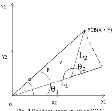
Fig. 2 illustrates the coordinate system of random point located on PCB (x, y) with respect to robotic arm.
Fig. 2 Random point (x, y) on PCB
2.1. Forward Kinematics
Location of end effector can be determined by the length of robotic a rm and rotation angle of each axis
𝑋 = 𝐿1𝑐𝑜𝑠𝜃1+ 𝐿2𝑐𝑜𝑠(𝜃1+ 𝜃2) (1)
𝑌 = 𝐿1𝑠𝑖𝑛𝜃1+ 𝐿2𝑠𝑖𝑛(𝜃1+ 𝜃2) (2)
2.2. Inverse Kinematics
Rotation angle of each axis can be determined by the coordinate system of end point.
2 2 2 2
1 1 2
2
1 2
cos
2
X Y L L
L L
(3)
1
2 2
1 1
1 2 2
tan Y tan L sin
X L L cos
(4)
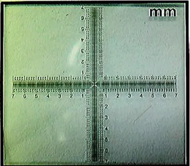
2.3. Compensation for Image and Distance Coordinate
Fig. 3 de monstrates the captured image of pixe l with respect to distance (1 pixe l equals to 0.01 mm). The origin o f d istance coordinate is located in the center of image coordinate and then pixe l (320, 240) would be the same as dis-tance (3.2mm, 2.4mm).
Fig. 3 Image/distance coordinate system
2.4. Compensation for deformed PCB Tray Coordinate
Fig. 4 presents the compensation for de-formed PCB tray coordinate. Assuming the PCB tray offset 1 mm due to thermal induced warp-age, the coordinate of random point in image capture system is determined.
𝑋2 = 𝑃𝐶𝐵 𝑋 + 𝑃𝑖𝑥𝑒𝑙 𝑋 (5) 𝑌2= 𝑃𝐶𝐵 𝑌 + 𝑃𝑖𝑥𝑒𝑙 𝑌 (6)
where X1=28.2, Y1=52.4 are system default parameters. After mathemat ical ca lculation, the placement coordinates are
𝑋 = 𝑋2− 𝑋1 (7)
𝑌 = 𝑌2− 𝑌1 (8)
Fig. 4 Schematic illustration of PCB coordinate system
2.5. Image Processing
Grayscale dig ital image is a range of shades of gray without apparent color. The reason for diffe rentiating gray images is that only specify a single intensity value for each pixel, i.e. less informat ion for each pixel. In order to reduce the comple xity of post-processing grayscale image scheme is applied to capture the characteristic image.
The Hough transform is a technique which can be used to isolate features of a particula r shape, such as line, circ le, e llipse, etc., within an image. Based on Hough transform, c ircula r detection on LabVIEW Vision Assistant is ap-plied to determine the p recise position on d e-formed PCB.
3.
Structure of Improved Placement
System
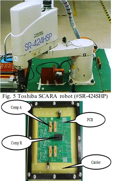
3.1. Hardware Description
Fig. 5 Toshiba SCARA robot (#SR-424SHP)
Fig. 6 SMD components on PCB with tray (carrier)
Fig. 7 Place ment system on trial run conveyor
The overall place ment system also consists of trial run conveyor for PCB tray, SM D co m-ponents feeder, buzze r, 3 cylinders (baffle, push and charge-in). 2 ca me ras (coordinate au-to-compensation and poka-yoke), 3 sensors with Arduino UNO and a lighting system (top and broadside). All SMD co mponents are held in specific trays which a re loaded in upstream vibratory parts feeding stations.
3.2. Software Development
The control software us ed in this study is Lab VIEW 2012 and Lab VIEW Vision Assistant 2012.
4.
Results and Discussion
Coordinate co mpensation system for SM D place ment and starved feeding (queliao) au-to-detection system have been developed in this paper. In the first, anchor point on PCB was shot by camera and the offset amount on PCB was then calculated by compensation of the image and distance coordinate. The precise location on PCB for co mponents placement was then d e-termined. For queliao and those parts did not place in the desired position, the developed system can a lso sound a buzzer signal on the control annunciator panel and warn the upstream feeding stations to load SMD components.
Fig. 8 Flow chart of coordinate compensation system for SMD placement
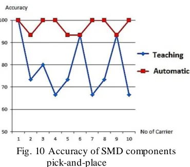
Fig. 8 and Fig. 9 present the flow chart for coordinate compensation system and queliao auto-detection system, respectively. Fig. 10 demonstrates the accuracy of SMD co mponents pick-and-place improved by the developed al-gorithm. The accuracy on auto assembly (99.73%) has been dramatica lly imp roved after teaching mode (78.66%).
Start
Capture SMD Image
Grayscale Digital Image
Hough Transform
Calculation Pixel Position for
Point (X, Y)
Fig. 9 Flow chart of queliao auto-detectionsystem
Fig. 10 Accuracy of SMD components pick-and-place
5.
Conclusions
In this paper, an improved pick-and-place SMD on PCB system has been accomplished by using SCA RA robot and mach ine v ision. The result has shown that 97.33% yie ld rate was achieved and more than 2% of erro r could be eliminated by improving the hardware of system. Besides top lighting camera, anchor point on the skewed PCB tray can be calibrated and revised by a broadside webcam. Re mote operation using wireless network is feasible.
Acknowledgement
The authors would like to e xp ress their ap-preciation to M inistry of Science and Technol-ogy, Taiwan, ROC, for financia l supports under project No. MOST103-2221-E-214-018 and MOST104-2221-E-214-051. Appreciation is also extended to Oriental Semiconductor Electronic, Ltd. for carrying out all the experiments.
References
[1] SCA RA, The ROBOT Hall of Fa me, Powe r by Carnegie Mellon,
http://www.robothalloffame.org/inductees/ 06inductees/scara.html
[2] A. Burisch, J. Wrege, A. Raatz, J. Hesselbach, and R. Degen, “PARVUS – miniaturised ro-bot for improved flexibility in micro produc-tion,” Assembly Automation, vol. 27, no. 1, 1980.
[3] S. K. Dwivedy and P. Eberhard, “Dynamic analysis of flexible manipulators, a literature review,” Journal of Mechanism and Machine Theory, vol. 41, no. 7, pp. 749-777, 2006. [4] A. Visioli and G. Legnani, “On the trajectory
tracking control of industrial SCARA robot manipulators,” IEEE Transactions on Industrial Electronics, vol. 49, no. 1, pp. 224-232, 2002. [5] G. S. Huang, C. K. Tung, H. C. Lin, and S. H.
Hsiao, “Inverse kinematics analysis trajectory planning for a robot arm,” Proceedings of 8th Asian Control Conference (ASCC 2011), Kaohsiung, Taiwan, pp. 965-970, May 2011. [6] J. Fang and W. Li, “Four degrees of
freedom SCARA robot kine matics modelling and simulation analysis,” International Journal of Computer, Consumer and Control, vol. 2, no. 4, pp. 20-27, 2013.
[7] F. Escobar, S. Díaz, C. Gutiérrez, Y. Ledeneva, C. Hernández, D. Rodríguez, and R. Lemus, “Simulation of control of a SCARA robot ac-tuated by pneumatic artificial muscles using RNAPM,” Journal of Applied Research and Technology, vol. 12, no. 5, pp. 939-946, 2014. [8] S. H. Han, W. H. See , J. Lee, M. H. Lee , and
H. Hashimoto, “Image-based visual servoing control of a SCA RA type dual-arm robot,” IEEE International Sy mposium on Industrial Electronics, Cholula , Puebla , Me xico, vol. 2, pp. 517-522, Dec. 2000.
[9] H. Zhu, J. Xu, D. He, K. Xing, and Z. Chen, “Design and implementation of the moving workpiece sorting system based on LabVIEW,” 26th Chinese Control and Decision Conference
Start
Image Captured
Image mask
Advanced Morphology
(2014 CCDC), Changsha, China, pp. 5034-5038, May 2014.
[10] R. Szabo and A. Gontean, “Robotic arm control with stereo vision made in LabWind
![Fig. 1 The first SCARA robot by Hiroshi Makino [1]](https://thumb-us.123doks.com/thumbv2/123dok_us/9831917.1969342/1.516.276.472.235.404/fig-scara-robot-hiroshi-makino.webp)