Combining Cloud Computing and Artificial Intelligence Scene Recognition
in Real-time Environment Image Planning Walkable Area
Jia-Shing Sheu
*, Chen-Yin Han
Department of Computer Science, National Taipei University of Education, Taipei, Taiwan
Received 18 May 2019; received in revised form 11 June 2019; accepted 20 August 2019 DOI: https://doi.org/10.46604/aiti.2020.4284
Abstract
This study developed scene recognition and cloud computing technology for real-time environmental
image-based regional planning using artificial intelligence. TensorFlow object detection functions were used for artificial
intelligence technology. First, an image from the environment is transmitted to a cloud server for cloud computing,
and all objects in the image are marked using a bounding box method. Obstacle detection is performed using
object detection, and the associated technique algorithm is used to mark walkable areas and relative coordinates.
The results of this study provide a machine vision application combined with cloud computing and artificial
intelligence scene recognition that can be used to complete walking space activities planned by a cleaning robot or
unmanned vehicle through real-time utilization of images from the environment.
Keywords: TensorFlow, computer vision, neural network, scene recognition, cloud computing
1.
Introduction
With the rapid development of technology, high-quality digital cameras have become commonly used for acquiring
images. These cameras are used in mobile phones, personal digital assistants, robots, medical systems, and surveillance and
home security systems. With machine learning and neural operations, the image in the cloud can be easily identified. This
study primarily used cloud resources currently available to upload real-time images from the environment obtained using a
digital camera to the cloud and cooperate with cloud machine learning and image recognition for identifying different
objects in the real-time image. When objects in a live image can be successfully identified, the environmental conditions
observed in the live image can be further distinguished. This study used these resources to map real-time images from the
environment to walkable areas by combining images obtained using digital cameras, which can be used with eye-like
cameras when combined with cloud machine learning and neural recognition.
In the study, Section 2 provides a review of the literature and methodology. The structure of the system is discussed in
Section 3. Design and experiments are provided in Section 4. Finally, conclusions are provided in Section 5.
2.
Literature Review and Methodology
An artificial neural network is a mathematical model based on a neural network system that mimics humans. The neural
network aims to establish a neural network model that mimics biological perception in a computer and uses this
mathematical statistical model to optimize data learning. In the cognitive system of artificial intelligence, the use of neural
network-like algorithms is more advantageous than formal logic inference algorithms. Because the neural network has
nonfixed, nonconvex, nonlinear, and nonlimiting characteristics, different structures, functions, and learning algorithms can
be used [1-3]. Neural networks can be classified into various types, such as perceptual neural networks, linear neural
networks, inverted-transitive neural networks, and enhanced neural networks. Because an inverse-transfer-like neural
network can approximate any function with arbitrary precision under appropriate parameter settings, it can effectively
predict the problem and provide functions such as environment perception, pattern recognition, and prediction. Neural
networks have been applied in many fields, including emotion perception, handwriting recognition, image recognition, and
language translation [4-7].
A neural network generally has several levels, and each level can provide a sufficient number of neurons. Each neuron
adds up the input of the previous layer of neurons and enters the conversion of an activation function. Each neuron has a
distinct connection with the neurons of the subsequent layer, and thus, the output value of the upper layer of neurons is
weighted and passed to the neurons of the subsequent layer. The neurons in the same layer are not connected and are distinct
[8-9].
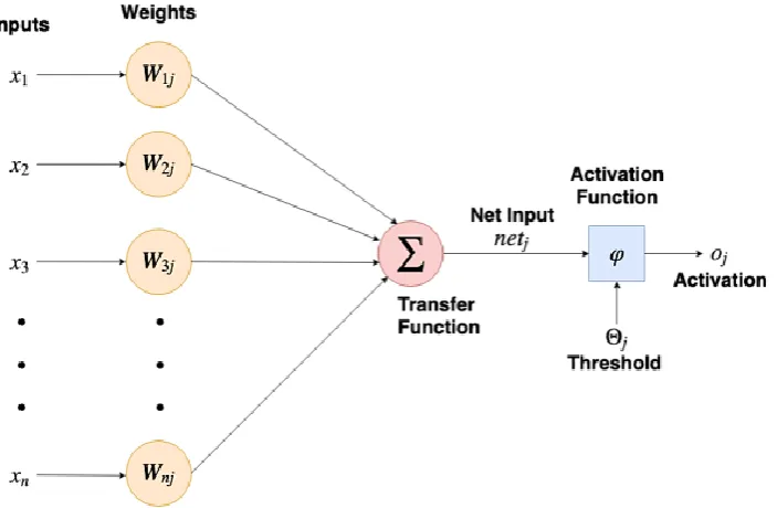
Fig. 1 Neural network-like simulation of how a single neuron operates
The neural network is represented by numerous single neurons as shown in Fig. 1, and comprises the following
components:
(1) Inputs: Receive signals from external or upper neurons.
(2) Weights: The memory of the neural network. The number of weights corresponds to the number of inputs in the input
layer; that is, one weight corresponds to one input, which is multiplied by a conversion function and then added to the
other values.
(3) Transfer function: The transfer function accumulates the product of all input values and weight values and then enters
the activation function.
(4) Threshold: Each neuron has a threshold. When the product value is accumulated by the conversion function, the offset
value is added. The excitation function is provided to determine whether the signal needs to be output downward. That
is, partial migration is used to control the continuation of the value.
(5) Activation function: An excitation function of the neural network introduces the characteristics of the nonlinear output,
and thus, the neural network can perform mapping to learn complex functions
(6) Outputs/Activation: The output values mapped using the excitation function can be used as inputs to the subsequent
The architecture of the neural network connects the aforementioned single neurons to form a model. Some commonly
used neural network architectures are inverted neural networks, convolutional neural networks, and recurrent neural
networks.
3.
System Structure
The study is primarily based on a neural network-based regional identification system, its focus being on detecting
walkable areas. By inputting images to a pre-trained neural network, the objects in the images can be identified. The empty
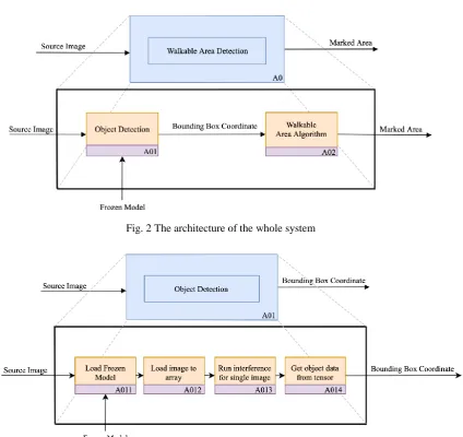
areas between objects indicate walkable areas. Fig. 2 presents the architecture of the system obtained from using IEF0 [10].
To achieve to mark walkable areas and relative coordinates, this study is divided into three parts:
(1) The first part constitutes neural network object identification. When the image enters the neural network, the trained
model is used to load the images into the personal computer, identify the object position, and predict the score and
object name.
(2) The second part involves finding the path. By using the object position and coordinates obtained using the neural
network, the distance between the objects is calculated, and the shortest distance between objects is identified to
determine the position of the empty area as shown in Fig. 3.
(3) The third part includes path marking. The two points with the shortest path are connected. The enclosed space inside the
line is the walkable area primarily discussed in this paper as shown in Fig. 4.
Fig. 2 The architecture of the whole system
Fig. 4 The architecture of walkable area marked
This experiment used TensorFlow as the core machine learning framework and an open source project TensorFlow
object detection application programming interface [11] as the core of object recognition, where the source code allows the
use of trained models that meet their requirements.
The pretraining model compiled using the TensorFlow detection model zoo was used in this study. The models used for
object recognition were faster_rcnn_inception_v2_atrous_coco, ssd_mobilenet_v1_coco, and ssd_mobilenet_v1_fpn_coco.
With the bounding box coordinates of the object, the distance between all bounding boxes can be calculated. The
algorithm uses the distance between each point to select the shortest path, which is considered a part of the walkable area and
is connected into a large block through the plurality of lines. According to an axiom in the Euclidean geometry system,
“there are two points and only one line,” and each bounding box has four points. Thus, for n bounding boxes, the following
general formula can be used in Eq. (1):
4
2n
n
2
n
4
(1)In any two bounding boxes, distance D between any two points is measured, which can be recorded as 𝑷𝟏(𝒙𝟏, 𝒚𝟏) and
𝑷𝟐(𝒙𝟐, 𝒚𝟐). The distance between all points is calculated using Eq. (2). For each length comparison, the two shortest
distance between all bounding boxes is selected, and starting and ending point coordinates are recorded.
2 2
2 1 2 1
( ) ( )
D x x y y (2)
The start and end point coordinates are obtained using the aforementioned method, and the line connecting the points
can form a closed area, which is the walkable area discussed by the research institute.
4.
Experimental Results
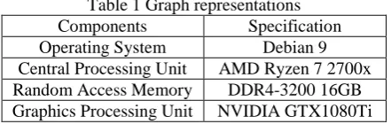
Table 1 Graph representations Components Specification Operating System Debian 9 Central Processing Unit AMD Ryzen 7 2700x Random Access Memory DDR4-3200 16GB Graphics Processing Unit NVIDIA GTX1080Ti
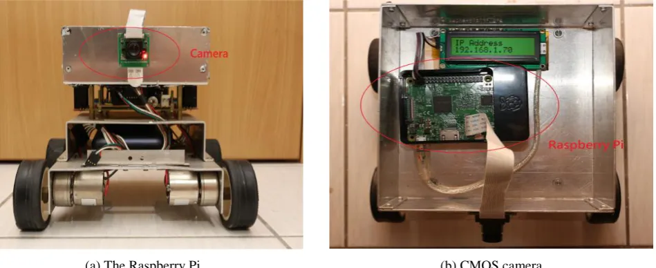
A car combined the Raspberry Pi and CMOS camera is used to capture the environmental image as shown in Fig. 5.
The Raspberry Pi is a popular embedded system, which is developed by the Raspberry Pi Foundation in the United Kingdom.
The processor is Boardcom BCM2837 SoC with a 1.2GHz 64-bit quad-core ARM Cortex-A53 processor. Raspberry Pi
module, sensors, etc. via Inter-Integrated Circuit (I²C), Universal Asynchronous Receiver-Transmitter (UART) and Serial
Peripheral Interface (SPI). Raspberry Pi also provides the accessories, such as touch panel and camera, the camera which is
this experiment used, the camera can get 1024 × 768 images by 5 million pixels, it connects Raspberry Pi by Camera Serial
Interface (CSI) with a flexible flat cable. Raspberry Pi’s power rating is 5V/1.34A (1.5W), we use a mobile power as a power source by MicroUSB, providing maximum 5V/2.4A (12W) output.
In this experiment, we use Wireless Local Area Network (WLAN) and Local Area Network (LAN) connect Raspberry
Pi and server. Raspbian was chosen for the operating system, it is a Debian-based for Raspberry Pi, officially provided by
Raspberry Pi Foundation. Raspbian is highly optimized for the Raspberry Pi line’s low-performance ARM CPUs, also
provide a desktop environment for beginners.
In the beginning, Raspberry Pi boots into the system, then startup streaming service, the protocol is using Real Time
Streaming Protocol (RTSP). At the server side, the server captures the image from Raspberry Pi, TensorFlow object
detection program will detect the object from the image, in this experiment, we use “faster_rcnn_inception_
resnet_v2_atrous_coco” as frozen model to detect object, the reason we chose this model, it can recognize object more than
the other two frozen model, but disadvantage of this model is using more time. After detected, the program will generate
object coordinate, name and detected score, to validate our theory, we need coordinate data to calculate the walkable area,
then, the program will send object coordinate data and source imaged to the walkable area program, name and score data are
optional data, but in this experiment, we didn’t use them, those data contain the object name and detected score.
The walkable area program was used in Python 3 as programming language, in this program, coordinate data from
TensorFlow object detection is playing an important part in this experiment, first step, we use the coordinate data to mark the
bounding box, second step, using the algorithm to find the walkable area of this image, then, the program will generate the
marked image.
(a) The Raspberry Pi (b) CMOS camera
Fig. 5 A car combined the Raspberry Pi and CMOS camera
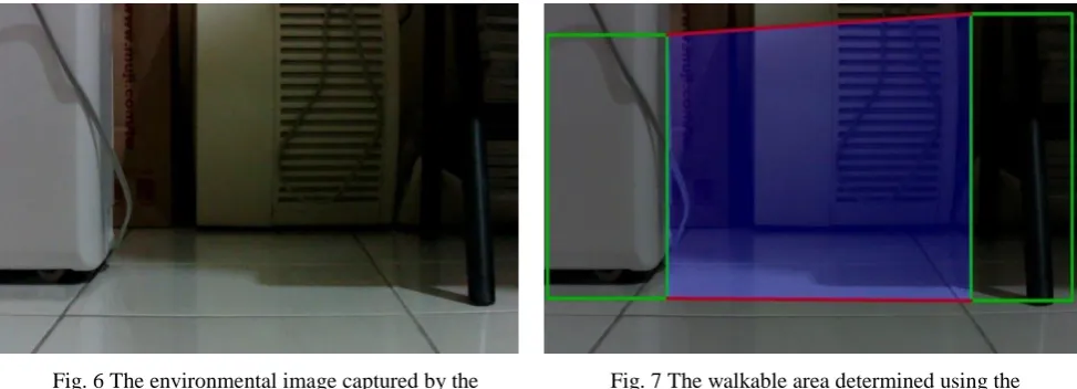
Figs. (6-7) present the original input, result detected using TensorFlow object detection, and walkable area determined
using the program, respectively. The program was developed according to the aforementioned theory. Fig. 7 shows the result
of the system output, bounding box in green represent the object, the two red lines represent the two shortest distance
between two bounding boxes, two lines means we have four coordinates. To show the walkable area, creating an empty layer,
same width and height as origin image, using these coordinates to create a polygon on it, filling in blue color in a closed area,
Fig. 6 The environmental image captured by the CMOS camera
Fig. 7 The walkable area determined using the system marked by BLUE COLOR
In Fig. 8, this environment is a walking area in the laboratory, in human thinking, we can pass through by the box’s
left-hand side, but there was a wheel of the chair in the left, so we pass through between these two objects. The program will
detect the objects using Fig. 8, then the program used an algorithm to calculate the walkable area between these two objects,
shown in Fig. 9. You can see that the program marks the walkable area by blue color, so does human thinking. But in Fig. 9,
some object is not marked, for example, the cabinet in the middle of Fig. 9, algorithm skip that object, the blue area is
overlapped on it.
Fig. 8 The environmental image captured by the CMOS camera
Fig. 9 The walkable area determined using the system, marked by BLUE COLOR
Fig. 10 The environmental image captured by the CMOS camera
Fig. 11 The walkable area determined using the system, marked by BLUE COLOR
_v1_ fpn_coco” are not used here, two of them can’t recognize more than two objects, by this reason, the algorithm needs
two or more objects input, which is the area that we want to find.
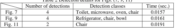
Table 2 Detection details for Figs. (7, 9, 11)
Number of detections Detection classes Time (sec.) Fig. 7 4 Toilet, microwave, oven, chair 0.0157
Fig. 9 4 Refrigerator, chair, bowl 0.0161
Fig. 11 2 Chair 0.0191
By experiment results, this algorithm needs more object data, accuracy will be increased. Choosing a model is a subject
in this study, we can train the model base on the existing model, so we should prepare the object that appears indoor
frequently, such as sofa, chairs, cabinet, fans, computers, etc. Another problem is, vision is limited, the camera cannot
capture whole object, only a part of an object, chair foot is an obvious case, sometimes object detection cannot detect what
the object is, or it is an object, cause the program cannot find the walkable area. The problem as descript above mentioned,
this problem is future work that we need to solve them.
5.
Conclusions
This study proposed the use of recent paths between all objects to determine the walkable area, the experiment showed
the result, it proofs the algorithm can find the walkable area by TensorFlow object detection. Enhanced this algorithm is the
most important job in the future, low latency is the goal of this algorithm, the real-time system does not allow high latency.
For example, the cleaning robot needs to know which area cannot entry, low latency can speed up the efficiency of the
cleaning work.
With the popularity of high-bandwidth networks, cloud computing was used to obtain the desired results. With
technological developments, the tensor calculation of embedded systems can considerably improve computing efficiency. In
the near future, this algorithm can be installed in embedded systems, which will be a significant development for robot
vision.
Conflicts of Interest
The authors declare no conflict of interest.
References
[1] S. Ren, K. He, R. Girshick, and J. Sun, “Faster R-CNN: towards real-time object detection with region proposal networks,”IEEE Transactions on Pattern Analysis and Machine Intelligence, vol. 39, no. 6, pp. 1137-1149, 2017. [2] T. Y. Lin, M. Maire, S. Belongie, L. Bourdev, R. Girshick, J. Hays, P. Perona, D. Ramanan, C. L. Zitnick, and P. Dollár,
“Microsoft COCO: common objects in context,”arXiv:1405.0312v3 [cs. CV], February 2015.
[3] A. G. Howard, M. Zhu, B. Chen, D. Kalenichenko, W. Wang, T. Weyand, M. Andreetto, and H. Adam, “MobileNets: efficient convolutional neural networks for mobile vision applications,” arXiv:1704.04861 [cs. CV], 2017.
[4] R. Girshick, J. Donahue, T. Darrell, and J. Malik, “Rich feature hierarchies for accurate object detection and semantic segmentation,” Proc. The IEEE Conference on Computer Vision and Pattern Recognition (CVPR), IEEE Press, June 2014, pp. 580-587.
[5] W. Liu, D. Anguelov, D. Erhan, C. Szegedy, S. Reed, C. Y. Fu, and A. C. Berg, “SSD: single shot multibox detector,” Proc. Part I: ECCV 2016-the 14th European Conference, Amsterdam, Netherlands, October 2016, pp. 21-37.
[6] K. He, X. Zhang, S. Ren, and J. Sun, “Deep residual learning for image recognition,” Proc. 2016 IEEE Conference on Computer Vision and Pattern Recognition (CVPR), IEEE Press, Jun. 2016, pp. 770-778.
[7] C. Ning, H. Zhou, Y. Song, and J. Tang, “Inception single shot multibox detector for object detection,” Proc. 2017 IEEE International Conference on Multimedia & Expo Workshops (ICMEW), IEEE Press, 2017, pp. 549-554.
[9] R. Kaluri and P. Reddy, “Optimized feature extraction for precise sign gesture recognition using self-improved genetic algorithm,” International Journal of Engineering and Technology Innovation, vol. 8, no. 1, pp. 25-37, 2018.
[10] C. H. Chen, C. M. Kuo, C. Y. Chen, and J. H. Dai, “RETRACTED: the design and synthesis using hierarchical robotic discrete-event modeling,” Journal of Vibration and Control, vol. 19, no. 11, pp. 1603-1613, 2012.
[11] M. Abadi, P. Barham, J. Chen, Z. Chen, A. Davis, J. Dean, M. Devin, S. Ghemawat, G. Irving, M. Isard, M. Kudlur, J. Levenberg, R. Monga, S. Moore, D. G. Murray, B. Steiner, P. Tucker, V. Vasudevan, P. Warden, M. Wicke, Y. Yu, and X. Zheng, “TensorFlow: a system for large-scale machine learning,” arXiv:1605.08695 [cs.CV], 2016.
Copyright© by the authors. Licensee TAETI, Taiwan. This article is an open access article distributed under the terms and conditions of the Creative Commons Attribution (CC BY-NC) license