“Set Phasors to Stun”: An algorithm to improve
phase coherence on transients in multi
microphone recordings.
Justin Paterson, London College of Music, Thames Valley University 19th International Congress on Acoustics
2-7 September 2007, Madrid, Spain “Acoustics for the 21st Century”
Correspondence should be addressed to Justin Paterson [[email protected]]
ABSTRACT
Ever since the advent of multi-microphone recording, sound engineers have wrestled with the colouration of sound by phasing issues. For some this was an anathema; for others this colouration was a crucial ingredient of the finished product. Traditionally, delicate microphone placement was essential, with subtle movements and tilts allowing the producer/engineer to determine when a sound was “in phase” based on perception alone. More recently, DAW’s have allowed us to view multiple waveforms and manually nudge them into coherence with visual feedback now supporting the aural, although still a manual process. This paper will present an algorithm that allows automatic correction of phase via a unique Max/MSP patch operating on multiple audio components
simultaneously. With a single button push, the producer can now hear a stereo recording with maximum coherence and thus make an artistic judgment as to whether the “ideal” is ideal, or better to pursue naturally occurring phase colouration in preference. In addition, the patch allows zoning in to spatially separated sound sources, eg tuning drum kit overheads to phase lock with the snare drum or hi-hat microphone. Audio examples will be played and the patch demonstrated in action. Limiting factors, contexts and
applications will also be discussed.
1. INTRODUCTION
Since the earliest days of utilising multiple microphones in a shared acoustic space, record producers and sound engineers have noted the effects of phase when recording. This is an inevitable artefact due to the different lengths of acoustic path from each point source to individual microphones. Phase is related to distance, differently for each
frequency component of any given sound, and so unless the point source was a sine wave emanating equidistantly from each microphone diaphragm, interference is going to produce some colouration of the recorded sound through comb filtering.
For example, a time delay of 1/1000 of a second would cause a 360 ° phase difference) in a 1000-Hz wave, but only a 180 ° phase difference for a 500-Hz wave. Thus a cancellation would occur at 500 Hz but not at 1000 Hz. This would correspond to a dip
at 500 Hz in the, frequency spectrum of the signal.
The phase lag φ, for any frequency f, for any given time delay t, may be given by
φ = 2πft Equation [1]
When two identical waves separated by a phase lag are added together, their sum is a wave whose amplitude depends on the phase lag.
[1]
When recording, this colouration was typically controlled by the physical adjustment of microphone placement. The audio spectrum contains wavelengths of approximately 17m to 1.7cm, and so adjustments to the order of less than a centimetre to a few centimetres would have a profound effect on the perception of the upper frequencies that were present. The effect was often associated (even attributed) to natural room ambience and utilised in recordings. Some purists found this “phasiness” undesirable and sought microphone placements that minimised it, often as a primary strategy when positioning these microphones. The phenomenon is most apparent when stereo recordings are summed to mono.
Much contemporary analysis of musical sounds has been based around windowing and phase vocoding techniques. Duxbury et al. [2] showed that separation of transients and steady state audio facilitated numerous applications such as transient enhancement and superior time stretching. Such an approach endeavours to maintain the integrity of the perceived musical information.
This paper takes a much simpler approach closer to that of typical manipulations the record producer might perform with small delay lines when dealing with phase anomalies embedded in a recording. A device created in Max/MSP that analyses transients and automatically applies the (subjectively) appropriate idealised delay purely in the time domain is presented. This device is equivalent to adjusting microphone position (distance from source), and provides the producer with a software environment to tighten transients in a multi-microphone recording, allowing the frequency dependant artefacts associated with such adjustments to still occur naturally in the steady state portion of the sound. A corollary of this is that the device can also be used to impose tone colour on the steady state portion if preferred.
Because two microphones separated in space pick up a sound at slightly different times, their combined output will be similar to the single microphone with delayed reflections. Therefore, spaced microphone
stereo-pickup arrangements are susceptible to comb-filter problems. Under certain conditions the combing is audible, imparting a phasiness to the overall sound reproduction, interpreted by some as room ambience. It is not ambience, however, but distortion of the time
some people find this distortion pleasing, so spaced microphone pickups are favored by many producers and listeners. [3]
It is in this spirit in which this work is pursued. As with recording itself, all of what follows must be considered “pre-mix”.
2. PRINCIPAL OBJECTIVES
Paterson [4] previously developed the algorithm as a component of “The One-T” in the quest to remove microphone spillage, in a two-microphone model. This was
re-contextualised for the purposes of this paper and the time correction must now function flexibly in a multi-microphone situation.
The specification of the required device might therefore present itself as follows. It must:
A] allow playback of multiple audio files, with loopable control to isolate and audition transients
B] be able to evaluate and then compensate for time delays (to sample accuracy) induced by the physical separation of microphones
C] be able to apply these delays both to individual files and to stereo pairs D] be able to manually control the delays for subjective and aesthetic appraisal E] be able to render new versions of the audio files with the delays embedded, so as to allow export into (Digital Audio Workstations) DAW’s for subsequent native operation
3. THE ALOGRITHM
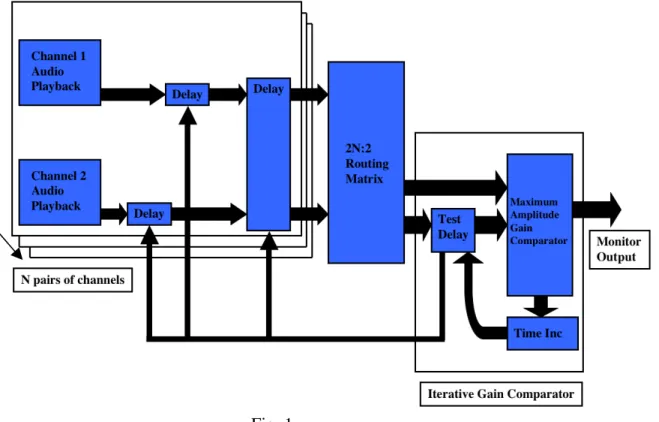
Fig. 1 below represents the algorithm needed to develop the Max patch.
Fig. 1
Functionality:
Channels 1/2 Audio Playback: “Channel 1 Audio Playback” is a buffer that holds a pre-recorded audio file from one of the microphones in the shared acoustic space. “Channel 2 Audio Playback” is that of another. Each of these is routed through its own sample accurate delay line, the values of which can be set/reset independently. The user can optionally configure the two buffers as a stereo pair, and a dedicated stereo delay line can act on them as a unit. This configuration is iterated N times to accommodate many
simultaneous audio signals, allowing various permutations of stereo and mono channels.
2N:2 Routing Matrix: This simply allows any channel (or pair of channels) to be fed into the subsequent section for comparison against any other channel (or pair of channels).
so the waveforms of each channel will have similar shapes, albeit with different amplitudes. Paterson [4] said
It has long been established that the generalised cross-correlation (GCC) method can estimate the delay present between two sensors [5], however this was shown not to work well in a reverberant environment [6]. This is a good reason to adopt this lateral
approach.
“In the reverberant environments, the performances of the conventional Time delay Estimator (TDE) methods are degraded due to interference and
reverberation [6]. The main reason is the disagreement between the ideal propagation model and the real signal model in reverberation [6][7].
Therefore, the TDE for the MA system should take account of the room transfer function (RTF) that models the room reverberation [7]. “ [8]
The work of [8] is primarily aimed at adaptive microphone arrays, but it would seem to imply that current technology has not yet addressed the simple convergence of transients, instead the focus being on Fourier based spectral analysis.
Fig.2 Clearly, the second samples will
produce the largest resultant sum of any combination
Audio channel 1
Audio channel 2 Time shift
The Iterative Gain Comparator comprises the:
Maximum Amplitude GaIn Comparator (MAGIC): Each of the two audio channels’ waveforms are monitored for the largest resultant peak when summed. As shown in Fig. 2, one channel’s time base is iteratively shifted by a single sample, and after each time shift, such a summation is performed. Maximum coherence of the transient peak is detected by recording the time shift that produces the maximum instantaneous gain when the channels are summed. Computational efficiency is
maintained by simple peak detection in the audio domain so computationally intensive convolution is not required.
Time Inc: A simple incremental counter that increases the delay time in “Test Delay” below.
Test Delay: This is the delay that shifts the time base iteratively by a single sample as described above. The user must monitor the (numerical) display meters on the GUI, and when a peak is detected, the test delay can be locked and the user can “A-B audition” the effect. The delay value can be then written to the appropriate delay
associated with an audio channel or stereo pair of audio channels. Once written, the target audio channel can be locked and the “Test Delay” applied to another channel etc..
Monitor Output: Monitoring was done monophonically to ensure accurate appraisal of comb filtering and any other artifacts.
It should be noted that each “Delay” features the ability for the user to manually adjust the delay time, lock this and compare with the idealized and zero delay. This is discussed further in section 8- Evaluation, below.
6. THE MAX PATCH
A Max/MSP patch was created to implement the above algorithm. Fig. 3 shows an example of the GUI of a pair of Audio Channels.
The upper slot is designated “Master” and it is on this slot that regions can be selected for looping and audition. One such region can be seen in the bluish area [a] in the centre of the waveform display. The “Master” slot happens to be a darker shade since it is currently selected and is being delayed by the “Test Delay”. The manual delays can be set with the faders [b]. Each channel has a gain control [c], and various options for subjective A-B comparison between zero, manual and MAGIC-automated delay times can be seen in the panels indicated by [d]. The stereo pair delay control area is given by [e]. The button indicated by [f] allows a new version of the audio to be written to the hard disk. This audio features the exact numbers of samples delay prepended as digital silence so that this file might be imported into a commercial DAW carrying with it the effect of the patch’s delay.
Numerous key commands are implemented to speed up operation and auditioning of combinations.
Fig.3
a
b c
d e
7. RESULTS
7.1OPERATION
At the present time, the patch is not wholly automated in its operation. It is left to the user to interact and control the audio to attain the preferred timbre.
7.2 TESTING
A number of audio examples were prepared:
The following test procedure is taken from Paterson [4]. This is wholly relevant since the maximum Amplitude Gain Comparator engine is identical:
7.2.1 A digital drum loop was created and a random cut was introduced into a clone of the loop to introduce an edit-delay in part of the audio. See Fig. 4. This audio was then rendered to form a contiguous file to compare with the unedited source audio. Both audio files were loaded into the patch.
Fig. 4
When a transient was selected and the patch asked only to calculate the delay, it was found that indeed the process was sample accurate. This was verified by phase inverting the second piece of audio, and complete cancellation from the original edit point was noted. Moving the delay manually by a single sample in either direction allowed images of the signal to audibly reappear, additionally verifying that sample accuracy was necessary in this process.
This is clearly an idealised task since the audio is identical apart from a time delay, however it was necessary to verify that this part of the algorithm functioned correctly.
7.2.2 is not relevant to this paper.
7.2.3 In order to evaluate the delay compensation in a more real-world situation, two sE Titan microphones were set up above a tom-tom, placed at deliberately different
distances as shown in Fig. 5.
Fig. 5
The patch indicated that a precise lock of transient should occur at 125 samples (at 44.1kHz sample rate), which equates to 2.834ms.
Using:
t=d/s Equation [2]
with a value of 340m/s for the speed of sound (an approximation dependant on the
hygrometrics, pressure and temperature of the environment), Equation [2] calculates the delay as 2.794ms. This is equivalent to a spatial error of around 1.5 cm, which could easily be a function of (the fairly crude) measurement or the above approximation. The effect on the transient was striking. Whilst the original recording exhibited a not unpleasant phasiness, once transient locked, the attack became much more pronounced and the body of the sound fatter. The effect was comparable with the common practice of setting the attack time on a compressor to around 20ms in order to accentuate the punch of a drum. Such a compression setting would not however influence the body of the sound.
7.2.4 The next test scenario came from a professional recording session; an album produced by the Author which featured an upright bass recorded with a sE Gemini, a Calrec 1050C and a contact microphone, as seen in Fig.6.
Contact Mic sE Gemini Calrec 1050C
Clearly, the Contact microphone is going to pick up the sound first, and will have a time difference relative to the two relatively distant microphones, which themselves may have some phase issues. The hugely experienced engineer, Paul Borg (right) set these
microphone placements aurally and achieved an excellent composite sound in the control room.
The three signals were processed through the Max patch. When only monitoring a
combination of Calrec and Gemini, a delay of 54 samples was detected by the MAGIC on the Gemini channel. The effect was a peak boost reported as 1.5dB, showing that there was convergence of transients. More significant however was an overall clarity of sound with a clearly enhanced low frequency energy, which was deemed better for this
instrument. This delay was locked for the Gemini, and the “Test Delay” was then applied to the Contact Microphone. When this was locked, the effect was dramatic. The patch now reported a 2.15dB peak increase, but the RMS was audibly greater. Fig.7 shows a sonogram image with a (logarithmic) frequency range of 50Hz-1500Hz, for a looped one
bar phrase containing several different pitches and articulations. The increase in low-end energy can be clearly seen as the delays were switched in and out.
The transients were more audible, and the whole result was superior. One anomaly was that when different notes were selected as sources for transient optimisation, the
recommended delay reported was different, typically within a range of +/- 20 samples. Although all were subjectively “better” than the original, it was not understood at the point of writing why this was the case. The manual delay controls proved most useful too, allowing both subtle and dramatic timbral changes, certainly facilitating the user’s “taste”.
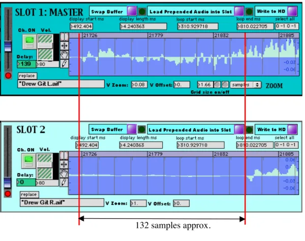
7.2.5 In a typical mix scenario, the above bass recordingwould be mixed into a single mono source in the panorama. In contrast, an acoustic guitar might be recorded and mixed in stereo. Upon request, a colleague crudely recorded a stereo acoustic guitar, in-camera with two Rode NT2 microphones. Placement to ensure phase accuracy was deliberately ignored to evaluate the restorative possibilities of the system. Fig. 8 shows that the time delay between the left and right channels is approximately 132 samples. The available grid in Max/MSP does not allow for easy sample accurate measurement. The system calculated the optimal delay to be within 10 samples of this, but once again, this varied depending on which transient was assessed. Again however, the sonic effect was dramatic, with a large and full sounding low-frequency enhancement with stronger transients. The peak levels rose by 3.5dB.
When monitored in stereo, the original recording had more integrity than it appeared in mono, but the time shifted one appeared richer and tighter, and interestingly seemed to have acquired a very slight although not objectionable “phasiness”.
50 Hz 1500Hz
With Delays
As recorded- no delay
132 samples approx. Fig. 8
Fig.9 again shows the low frequency enhancement when switching the delay on and off, although this time the bandwidth shown is approximately 12kHz.
Fig. 9 50 Hz
7.2.6 Drums. Recording a drum kit proficiently is an incredible feat of dealing with multiple phases from the multiple microphones. The overheads capture a stereo image of the entire kit, each component of which is at different distances from them due to the physical size of the drums and cymbals. These are then combined with numerous close mics and often secondary ambient pairs at distance.
A professionally recorded kit was employed for evaluation. The microphones were a spaced pair of AKG 414s on cardioid with no bass pad for overheads, a pair of Neumann U87s on cardioid about 2.5 meters in front of the kit for ambience (about 2.5 meters high), a Shure SM57 on top of the snare and an Electrovoice RE20 on the bass drum. Other close microphones were present, but were not considered in this paper.
The overheads were visually inspected, and the earliest one ascertained. The zoom view can be seen in Fig. 10. The scale is in samples.
Fig. 10
relative to the snare, the two ambient microphones again were greatly improved with the snare showing similar improvements to the overheads.
When the two locked pairs were monitored together, there was a most pronounced
difference in the sound. A low frequency enhancement on the snare (and its ambience) as with other instruments was noted. It was now possible to determine a very short
flamming on the snare transient. This seemed to be because the focus of the individual pairs was more accurate- in two places rather than in four. The “side-effects”; the bass drum appeared lower in pitch (a possible side-effect of comb filtering), but not as full sounding. The ride cymbal had lost some of its sustain, and again a slight flam was perceptible.
Fig. 11 shows the display of the two pairs. The upper two are the overheads, and the lower two are the ambients.
The MAGIC now interrogated the two locked pairs against each other. The system reported that 155 samples was the optimum. Given the inaccuracies of the grid in Max/MSP, this was closely in line with the distances mentioned above.
There was a most pronounced audible difference. The flams had disappeared from both snare and cymbal, and both were highly focussed. The snare assumed a more powerful quality, and the ride became more tonal with a stronger transient.
The snare drum close mic was now included and delayed against the now locked two pairs. Once compensated for by the MAGIC recommended 254 samples (5.75ms)- in line with the large delay incurred by the ambient pair, gain increased by 1.6dB and there seemed to be much more body to the sound. All other parts of the kit seem to benefit from this too. The bass drum appeared “fatter” and the ride had more body with a “singing” quality.
Lastly the bass drum microphone was included. The bass drum appeared to have a slight flam when combined with the rest of the kit, but when a MAGIC 103-sample delay was applied the flamming disappeared and it appeared more “solid”. It did however lose a small amount of its tone. The peak transient was measured with an increase of 0.7dB. All delays were A-B-ed with the original state of the recording, and there were obvious differences. It was the Author’s view that the modified recording had more power and focus, although such a view is subjective and contextual to the accompanying music. The sonogram did not yield interesting results, primarily due to the noise like quality of drums and cymbals.
8. EVALUATION
The algorithm has been proven to have a dramatic effect on various forms of audio. The results are of course subjective. It is clear that using purely time domain manipulations of this fashion, phase artefacts will be inevitably introduced at the expense of any transient correction. The question is whether that is acceptable or even preferable. Much
technology is developing to separate transients and steady states, but this is less analogous to simple microphone placement in which spirit this work developed. One unresolved issue is that of why the selection of different transients from the same performance yielded different results. Possible solutions might be the time-variant resonances of elements of the instruments, or the effects of room interaction. This should for the subject of a future investigation.
It is notable that whilst a single sample of delay can be audible in certain conditions, there appeared to be a “capture-range” within which the time-correction would have some of the desired effect.
The temporary appearance of flam-like phenomena is interesting. These were not
another. It was deemed satisfactory that these issues were resolved by subsequent iterations of the process.
An interesting sub-text is the formation of an environment for easily applying minute delays to the various components of a multi-microphone recording. This allowed not only manual overrides of the machine’s estimation according to taste, but also the convenience of a sound-shaping tool based on phase alone.
Eminent engineer, Gregg Jackman bases his whole recording practice around transients. He told the Author:
Transient response is massively more important than frequency response. This is why people like recording to tape. It limits transients. Different speakers and microphones respond to transients differently- their frequency response curves all look about the same. This paper demonstrates the validity of his recording philosophy.
9. FUTURE DEVELOPMENTS
Numerous possibilities for future developments of the work present themselves:
Plug-in version: If the patch were configured as a plug-in, users could work wholly within their preferred DAW.
Separation of the transient from the body of the sound: Using multiresolution analysis techniques as proposed by Duxley et al. [2] would allow transient enhancement
independently from the comb filtering artifacts induced in the steady state portion of a sound.
Stereo Evaluation: Automated searching for the absolute earliest channel of a stereo signal could provide a sure reference for subsequent delay operations, removing the current necessity for user confirmation.
Full Automation: This could be implemented so that the entire process was MAGIC-automated for multiple microphones. Current thinking tends towards the exploration of sonic possibilities, but some users might prefer a true “one button” solution.
Investigate the Effect on Other Forms of Audio: Further experimentation needs to be done on other forms of audio. Orchestral recordings will prove particularly interesting. It is common to use ambient pairs and even numerous pairs on the sections, sometimes with the aid of spot microphones on individual instruments.
10. CONCLUSION
This paper only serves as an introduction to the applications and potential results. The principle offers radical new approaches based on well-understood technology and the most simple of ideas. Perhaps the bottom line is whether the producer, engineer or artist prefers the corrected sound. Grammy award winning producer Pip Williams told the Author:
Sometimes the client prefers it out of phase. Both “Status Quo” and “The Moody Blues” have preferred the snare drum OUT of phase!
ACKNOWLEDGEMENTS
Thanks to Pip Williams for producing, Gregg Jackman for recording and Matthew Letley for performing the drum excerpt, taken from Status Quo’s “Pennsylvania Blues Tonight”, album untitled at the point of writing. Thanks also to John Edwards performing the bass excerpt, and Paul Borg for recording it; taken from “The Making of Quiet Things” by “The Number” featuring Keith Tippett, produced by the Author. Thanks to Drew
Downing for the guitar performance and recording of that excerpt, and to Sebastian Lexer for the small piece of code which the “Write to HD” section of the patch is based on.
REFERENCES
[1] Bartlett, Bruce, “A Scientific Explanation of Phasing (Flanging)”, J. Audio Eng. Soc., 18, 6
pp. 674, 675, 1970
[2] C. Duxbury, M. Davies, M. Sandler, “Separation of Transient Information in Musical Audio using multiresolution Analysis Techniques”
Proceedings of the COST G-6 Conference on Digital Audio Effects (DAFX-01), Limerick, Ireland, Dec. 6-8, 2001
[3] Everest, F. Alton. “Master Handbook of Acoustics”’
Blacklick, OH, USA: McGraw-Hill Professional Publishing, p 375, 2000
[4] J. Paterson, “Killing Spillage” Proceedings of the Art of Record Production (ARP) Conference, Edinburgh, Scotland, Sept. 2006
[6] B. Champagne, S. Bedard, and A. Stephenne, “Performance of time-delay estimation in the presence of room reverberation,” IEEE Trans. Speech Audio Processing, vol. 4, no. 2, pp. 148-152, Mar. 1996.
[7] J. Benesty, “Adaptive eigenvalue decomposition algorithm for passive acoustic source
localization,” Journal Acoust. Soc. of America, vol. 107, no. 1, pp. 384-391, Jan. 2000.
[8] Choi, Seung Jong; Jung, Yang-Won; Kang, Hong-Goo; Kim, Hyo Jin “Adaptive Microphone Array with Self-Delay Estimator”