RESEARCH ARTICLE
3D finite element coupled analysis model
for geotechnical and complex structural
problems of historic masonry structures:
conservation of Abu Serga church, Cairo, Egypt
Sayed Hemeda
*Abstract
This research presents the damage mechanism of a historical masonry architecture induced by differential settlement based on 3D FE analysis. The purpose of the study was to investigate the behavior fully-saturated soft clays subjected to self-weight loading from an old masonry structure of Abu Serga church which is the oldest church in Egypt dating back to the fifth century A.D and located in old Cairo area in Cairo city. The church gains its high prestige to having been constructed upon the Holy crypt of the Holy Family where they stayed during their sojourn in Egypt. The main objective of the present study is too accurately record and analysis the geotechnical problems and induced struc-tural failure mechanisms observed and calculated in the field, experimental and numerical studies. The land area is also susceptible to floods. Numerical analysis for such geotechnical problems is largely expected to contribute to the conservation of cultural heritages. The present research presents an attempt and pilot study to design the PLAXIS 3D FE model to simulate ground problems, and to distort and analyze the stress of the complex structure of the Abu Serga church, which is loaded on plane level. Plastic modeling or Mohr–Coulomb model in advanced soil was used during the various stages of numerical analysis. Results are recorded and discussed with respect to stress and volu-metric behavior of soil. Finally, the study represents the design studies and implementation of the inter-organizational retrofitting intervention and strengthening project for the oldest Coptic church in Egypt.
Keywords: The oldest Coptic church, Geotechnical modeling, Soil problems, Historic structures, Problematic soils, Soil settlement, 3D constitutive models, FE PLAXIS 3D, Vertical displacement
© The Author(s) 2019. This article is distributed under the terms of the Creative Commons Attribution 4.0 International License (http://creat iveco mmons .org/licen ses/by/4.0/), which permits unrestricted use, distribution, and reproduction in any medium, provided you give appropriate credit to the original author(s) and the source, provide a link to the Creative Commons license,
and indicate if changes were made. The Creative Commons Public Domain Dedication waiver (http://creat iveco mmons .org/
publi cdoma in/zero/1.0/) applies to the data made available in this article, unless otherwise stated. Introduction
Historical monuments are invariably exposed to the influence of the geological environment. Given the lifespan of such structures, several dynamic geologi-cal processes (weathering/erosion, surface movements and earthquakes) usually have a dramatic impact on the integrity of the monuments.
The protection of monuments requires special approaches in terms of adaptation of the engineering
interventions to the historical environment and the life-time of such interventions.
The significant cost and implicit long-term effective-ness of engineering schemes for the protection of his-torical monuments necessitates integrated approaches requiring on-going validation of the design. The co-oper-ation between the designer and the contractor during construction and long-term performance monitoring are key components for the success of such undertakings.
Structural damage to the architectural heritage is often caused by the displacement of the earth’s soil, its differential settlement, its rotation, or any other effect of the interaction between the structure and the soil. Although it is necessary to examine both the shear
Open Access
*Correspondence: [email protected]
resistance and the underlying settlements of any struc-ture, the research is very limited and focuses on mecha-nisms of failure of superstructures only [1–7].
To determine the magnitude of stresses, analyze the deformation and settlement of the soft silty clay soil and the superstructure response, an analytical coupled model of geotechnical and structural engineering is presented in detail. Geotechnical numerical modeling of complex soil structure problems requires advanced three-dimensional advanced soil models. PLAXIS 3D (PLAXIS v.b 2018) was used to calculate the soil settle-ment due to consolidation and the impact of its accom-panied pressures and stresses on the superstructure. It is a program produced for the geotechnical construc-tion plan and inquired about it and was used late as part of the structural and geotechnical survey. The Mohr–Coulomb model is used for both static assem-bly and rigidity inspection. The code contains a use-ful methodology for the programmed batching drive, called Load Advancement, which we used here [8–10].
Constitutive models are the key-stone not only for understanding the mechanical behavior of soils but also
for carrying out numerical predictions by means of the FE method [11, 12].
Since 1970s, there are extensive studies on elastic– plastic model about saturation soil under dynamic load-ing. Building model under monotonic loading and using relatively complicated hardening law, such as the model based on modifier Cambridge model by Carter [13], the Desai model with single yield surface built in 1984 [14]. The dynamic model based on other types of plasticity theory, such as multi-surface model built by Mroz et al. and Provest [15, 16], secondary loading surface model built by Hashiguchi in 1993, the plasticity model of sand based on multi-mechanism conception under cyclic loading by Kabilamany, Pastor et al. [17, 18].
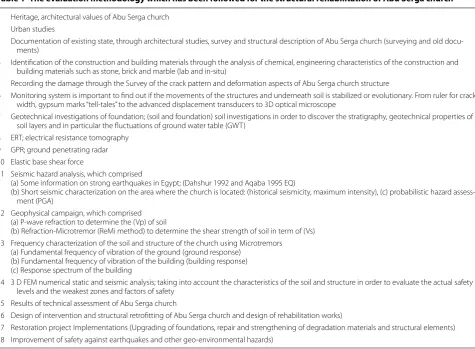
The evaluation methodology which has been followed for the structural rehabilitation of Abu Serga church (which is located in old Cairo area in Cairo) comprised the following phases/actions, as summarized in Table 1.
Methodology established for the study of historic masonry structures were assessed in terms of their reli-ability, accuracy and effectiveness by comparing analyti-cal results with experimental and empirianalyti-cal data [19, 20].
Table 1 The evaluation methodology which has been followed for the structural rehabilitation of Abu Serga church
1 Heritage, architectural values of Abu Serga church 2 Urban studies
3 Documentation of existing state, through architectural studies, survey and structural description of Abu Serga church (surveying and old docu-ments)
4 Identification of the construction and building materials through the analysis of chemical, engineering characteristics of the construction and building materials such as stone, brick and marble (lab and in-situ)
5 Recording the damage through the Survey of the crack pattern and deformation aspects of Abu Serga church structure
6 Monitoring system is important to find out if the movements of the structures and underneath soil is stabilized or evolutionary. From ruler for crack width, gypsum marks “tell-tales” to the advanced displacement transducers to 3D optical microscope
7 Geotechnical investigations of foundation; (soil and foundation) soil investigations in order to discover the stratigraphy, geotechnical properties of soil layers and in particular the fluctuations of ground water table (GWT)
8 ERT; electrical resistance tomography 9 GPR; ground penetrating radar 10 Elastic base shear force
11 Seismic hazard analysis, which comprised
(a) Some information on strong earthquakes in Egypt; (Dahshur 1992 and Aqaba 1995 EQ)
(b) Short seismic characterization on the area where the church is located: (historical seismicity, maximum intensity), (c) probabilistic hazard assess-ment (PGA)
12 Geophysical campaign, which comprised (a) P-wave refraction to determine the (Vp) of soil
(b) Refraction-Microtremor (ReMi method) to determine the shear strength of soil in term of (Vs) 13 Frequency characterization of the soil and structure of the church using Microtremors
(a) Fundamental frequency of vibration of the ground (ground response) (b) Fundamental frequency of vibration of the building (building response) (c) Response spectrum of the building
14 3 D FEM numerical static and seismic analysis; taking into account the characteristics of the soil and structure in order to evaluate the actual safety levels and the weakest zones and factors of safety
15 Results of technical assessment of Abu Serga church
16 Design of intervention and structural retrofitting of Abu Serga church and design of rehabilitation works)
Geotechnical conditions and monitoring
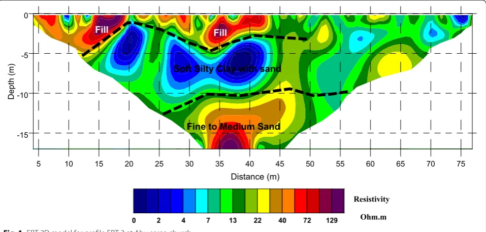
The subsurface conditions of the Abu Serga church con-sists of multi layers of thick soft clay mixed with vari-able sand. The fine sandy layers are shown to the middle at a depth of 6 m below the floor level of the chapel. The subsurface water appears at a depth of 1.8 m [21]. Figure 1 shows the ERT-3 reflection model on the main street of Mar Girgis, at a height of 5 m above the level of the ground floor of the church.
The geotechnical investigations carried out on the extracted soil samples. Data was collected from five (5) (boreholes), four (4) (PCPT/CPT), and eighteen (18) Undisturbed Samples (US). The results of laboratory tests were selected over eleven (11) grain size distribu-tions, five (5) oedometer tests, three (3) direct shear tests, six (6) triaxial CU+ u tests and five (5) triaxial UU tests. The geotechnical testing has been carried out in the Soil Mechanics Laboratory of Faculty of Engi-neering, Cairo University.
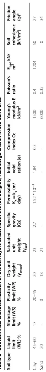
The physical and geomechanical characteristics of bearing soil layers under church are presented and summarized in details in Table 2.
CPT and CPTu data reveal that the soft clay soil layer is characterized by a tip resistance (qc) lower than
1 MPa and the friction ratio is between 1 and 3.
For Sand Layers: Atterberg limits, liquid limit (WL) = 20, plastic limit (Wp) = 0, dry unit weight γdry= 18 kN/m3, saturated unit weight γsat= 21 kN/
m3. For the elastic parameters, Modulus of Elasticity
E = 6000 KN/m2 and Poisson’s ratio υ = 0.35. For the shear strength parameters of this sand, the cohesion of
grain particles c = 0 kN/m2 and internal friction angle
φ = 34.
By the dewatering project in 2000, differential soil con-solidation settlements were recorded between different parts of the subsoil and structures of Abu Serga church and other surrounding churches and chapels in the area. Settlements have been calculated up to 0.9 cm at the areas of filter wall in the old Cairo archaeological area.
Engineering properties of building materials Another important parameter, necessary for the complete documentation of the structure and for understanding its behavior and response due to the subsoil settlement, is the identification of construction and building material engineering properties, which may have different charac-teristics depending on construction phases of the historic masonry structure.
Table 3 summarized the engineering properties of the different construction and building materials
Thirty brick samples and specimens have been col-lected from different locations in the structure of Abu Serga church, and the physical and mechanical testing have been achieved in the Laboratory of Building Materi-als in Faculty of Engineering in Cairo University by the author. The averaged results indicated that; (1) Physical properties, for specific gravity (Gs) it is ranged between 1.8 and 2.0 g/cm3, water absorption (Wa) is 20.1%,
Poros-ity (n) is 27%. (2) Mechanical properties, uniaxial com-pressive strength (σc) is 1.6–4.7 MPa, Brazilian splitting
tensile strength (σt) is 1.8 MPa, primary wave velocity
(Vp) is 1.71 km/s, static Young’s modulus (E) is 8.4 GPa,
5 10 15 20 25 30 35 40 45 50 55 60 65 70 75
Distance (m) -15 -10 -5 0 Depth (m) Fill Fill
Soft Silty Clay with sand
Fine to Medium Sand
0 2 4 7 13 22 40 72 129
Resistivity
Ohm.m
Table 2 G eot echnic al char ac teriza
tion of the soil la
yers undernea th the (S t. S er gius) A bu S er ga chur
ch in old C
air
o ar
ea
Soil t
ype
Liquid limit (WL) %
Shrink age limit ( W S) % Plasticit y limit ( WP ) % D
ry unit weigh
t (γunsa t ) Sa tur at ed
unit weigh
t
(γsat
)
Specific gravit
y (Gs) Permeabilit y Kx = ky (m/ da y)
Initial void ration (e)
Compr ession inde x C c Young ’s
modulus E kN/m
2 Poisson ’s ra tio Eoed kN/ m 2
Soil cohesion c (kN/m
2)
Fric
tion
angle (φ)°
dynamic Young’s modulus (Edy) is 2.4 GPa, and Shear modulus (G) is 917 MPa. The results from the physical and mechanical testing referred that the main construc-tion materials of the church which is the bricks are in advanced state of deterioration and demand a necessary strengthening and retrofitting interventions.
Red bricks and the hydraulic mortars were of the most important construction materials used in the Coptic churches including the subject of the present study “Abu Serga church” in the old Cairo. Generally the studied fired brick is formed mainly of quartz and feldspar grains.
These grains are embedded in a ferruginous dark brownish groundmass formed mainly of iron oxides
(hematite) and burnt clays. The bricks have various colors and dimensions and formed mainly from local raw mate-rial (Nile sediments) together with some additives (rice hush and/or plant ash to improve their properties. They are of medium density, high porosity due to the weather-ing activities (subsurface water and salt weatherweather-ing. They have wide range values of their physical and engineer-ing characteristics (e.g. specific density, water absorp-tion, porosity, ultrasonic velocity uniaxial compressive strength σc, static modulus of elasticity, dynamic
modu-lus of elasticity, and shear stress).
Ten marble samples and specimens have been collected from the fallen fragments and from different deteriorated Table 3 Engineering properties of the different construction and building materials of Abu Serga church
Gs specific gravity, Wa water absorption, n porosity, σc uniaxial compressive strength, σt splitting tensile strength, E Young’s modulus, Vp compressional wave velocity,
Edy dynamic Young’s modulus, G Shear modulus
Sample Gs (g/cm3) Wa (%) n (%) σ
c (MPa) σt (MPa) E (GPa) VP (km/s) Edy (GPa) G (MPa)
Brick 1.8 20.1 0.27 1.4–4.7 1.8 8.4 1.71 2.443 917
Marble 2.7 0.12 0.32 16 6 30 2.87 10.921 1195
Wood 0.64 30 – 8 3 7 – – –
locations in the marble columns inside Abu Serga church. The averaged results indicated that; (1) Physical properties, for specific gravity (Gs) it is ranged between 2.6 to 2.8 g/cm3, Water absorption (Wa) is 12%,
Poros-ity (n) is 32%. (2) Mechanical properties, uniaxial com-pressive strength (σc) is 16 MPa, Brazilian splitting tensile
strength (σt) is 6 MPa, primary wave velocity (Vp) is
2.87 km/s, static Young’s modulus (E) is 30 GPa, dynamic Young’s modulus (Edy) is 11 GPa, and Shear modulus (G) is 1195 MPa. The results indicated a very poor mechani-cal characterization of these marble columns which could affect the stability of these structural columns and induced the deformation patterns which is obvious.
Four wooden samples and specimens have been col-lected from different locations in the roof of Abu Serga church. The field observation and the averaged results of the mechanical testing indicated that the structural wooden beams which support the roof are deflected in high value due to the overloading and the material decay and degradation; (1) physical properties, for spe-cific gravity (Gs) it is ranged between 0.64 to 0.69 g/cm3,
Water absorption (Wa) is 30%. (2) Mechanical proper-ties, uniaxial compressive strength (σc) is 8 MPa,
Brazil-ian splitting tensile strength (σt) is 3 MPa, Static Young’s
modulus (E) is 7 GPa.
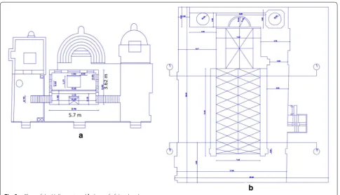
Fig. 3 a Plans of the Holly crypt, and b the roof of the church
The architectural design of Abu Serga church
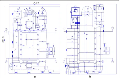
Abu Serga church is a small chapel with a length of 29.4 m and a width of 17 m and a height of 15 m. The ground floor is about 1.5 m under the surrounding alleys and 4.5 m down St. George’s Main Street. It features a typical basilica design with a gallery leading to a nave with two side aisles, and these passages are separated by twelve equal marble columns of row.
Three sanctuaries occupying the eastern side of the church. In the northern and southern ones, there are internal underground stairs leading to the Holly crypt. The height of the Holly crypt is about 6.5 × 5 × 2.5 m with two columns rows containing a longitudinal series of arches on each row. These two rows of columns are divided into three long shallow domes, which can be con-sidered a plateau with northern and southern passages. [22] Modern architectural surveys and studies presented in this study indicated that the length of the church is 29.40 m and its total width, including the external open
court accompanying 24.50 m, as shown in Figs. 2, 3, 4, and 5.
State of Abu Serga church preservation
Numerous local cracks and deformation patterns were observed and recorded mainly during the old fluctuations of the Nile before to the construction of the Aswan High Dam in 1968 (ancient dams that caused the loading and unloading of the underground layers under the historic building structures) and during the water removal pro-ject (Contract 102 in 2000) to reduce groundwater in the Old Cairo area.
The main problems of the structural elements and material decay of the structural component of the his-toric masonry structure of Abu Serga church can be sum-marized as follow:
Abu Serga church suffered great deterioration due to the extensive cracking due to the settlement of the sub-soil and the surface movements.
Almost causes of structural deficiency and damage seem to be four of the mechanical static and dynamic actions, affecting the superstructure of the church:
A. Differential consolidation settlement due to the plane loading of the superstructure on the full saturated Fig. 5 a Representative 3Dimension model of the church display
its two main entrances. b 3Dimension representative model of the church, display the main northern entrance
clay soil and expulsion of the pore water, also the dif-ferential settlement due the shear failure of the soil layer under the heavy loading and the poor geotech-nical characteristics of the soft bearing clay layer, also the fluctuations of the subsurface water can reduce the bearing capacity of the bearing soil to 50%. The dewatering project in the old Cairo area in 2000 was one of the causes of soil settlement due to consolida-tion of the thick fully saturated clay layer.
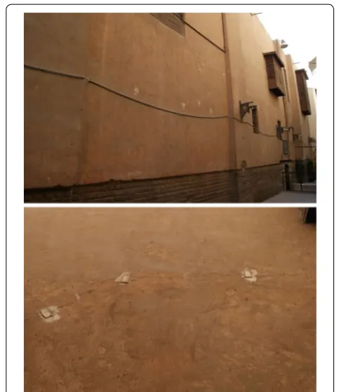
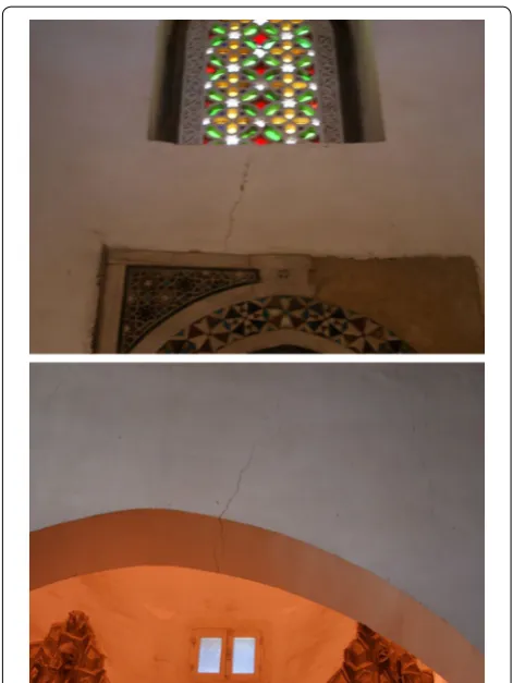
The internal deformities of the two facades of the church are clear, as shown in Fig. 6. Settlement and the rotation and inclination of the structural marble col-umns and the different cracks in the arches inside the church are well observed; also the vertical cracks in the lintels inside church are shown in Fig. 7.
B. Seismic loading, according to historical facts the power-ful earthquakes and the recent earthquakes in particu-larly the Dahshur earthquake 1992 and Aqaba earth-quake 1995, that have stuck old Cairo area, caused small or medium damages to Abu Serga church.
C. Degradation of construction and building materials, moisture often plays the important and main role of the degradation of the building materials. The main source of the humidity is the subsurface water and high groundwater level for a long period of time.
The technical evaluation of the brick walls provided a general case of in and out of plane deformations.
D. The excavations of the underground metro; many damage and deformation patterns well observed through the structure of the church due to excavation induced subsidence.
Constitutive modeling (numerical analysis)
In this study; PLAXIS 3D performed with a plastic mate-rial model to determine the behavior and nonlinear response of the saturated soft silty clay soil and masonry structure of the church. Plaxis is a commercially avail-able program which is using finite element method FEM. Plaxis is using different soil models to define soil behavior such as Mohr–Coulomb Model, Hardening Soil Model, Soft Soil Model, Soft Soil Creep Model, Jointed Rock Model and Modified Cam-Clay Model. Mohr–Coulomb Model is chosen for this study because it is commonly used and not required extra soil parameters.
The Linear-Elastic Perfectly-Plastic Mohr–Coulomb demonstrate includes five information parameters, i.e. Young’s modulus E and Poisson’s ratio nu (ν) for soil flex-ibility; Cohesion c, friction angle phi (φ) and dilatancy psi (ψ) have to do with soil shear behaviour. The Mohr–Cou-lomb model represents a ‘first-order’ approximation of soil or rock behaviour.
Mohr–Coulomb model is a straightforward and perti-nent to three-dimensional stress space model to depict the plastic conduct of earth soil and its immersed con-duct and related stream. As to quality concon-duct, this model performs better. This model is applicable to analy-ses the stability of shallow foundations and the soil prob-lems. For Mohr–Coulomb flow rule is defined through the dilatancy angle of the soil. In soft soils volumetric plastic strains on shearing are compressive (negative dila-tion) whilst Mohr–Coulomb model will predict continu-ous dilation.
Numerical modeling of the plane strain using the PLAXIS 3D (version 2018) was adopted. Consists of 15 nodes of finite trigonometric elements with a medium precision network to reduce the calculation time. All the geotechnical characteristics of the soil layers and engineering characterization of the building materi-als of Abu Serga church are listed in Tables 2 and 3. The
Mohr–Coulomb constitutive law was chosen to describe the behavior of saturated soft clay behavior. The water is located at 1.8 m deep. The settlement was monitored according to the time given for the actual settlement [3].
Subsoil behavior is studied in details.
The masonry structure of the church was modeled using solid element module, the solid element properties taken as defined above in design criteria [23, 24].
The church was modeled using frame elements for marble columns and shell elements for the ceilings with same properties in the mentioned reports above.
Rigid links are used to connect all brick walls together to act as one unit, rigid links defined with very high moment of inertial and weightless. Elements cross sec-tions solid elements thickness varies from 160 to 70 cm along the height. Beams cross sections 25 cm * 80 cm. Slab thickness is 16 cm.
Results of numerical analysis
Successful use of a mathematical analytical model can provide information on the type, extent and location of damage and unsafe zones and safety levels.
The results of the numerical analysis of church are shown as originally designed that some of the surface
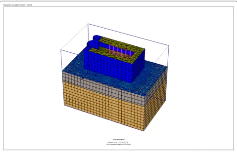
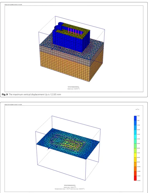
subsidence occurred during its construction on thick layers of soft clay (6 m) and because of the drainage or dewatering project in 2000. Displacement developed on the surface, above the maximum value of about 122.85 mm, is the total consolidation settlement and fail-ure of local shearing of the soil due to the in-plane load-ing. Figure 8 shows the geometry and FE discretization of the 3D model and the deformed mesh and the calculated vertical displacement Uy of the saturated silty clay soil with the structure loading and appears distributed under the superstructure of the church in Figs. 9 and 10, the extreme value Uy is 122.85 mm. The volumetric strain εv
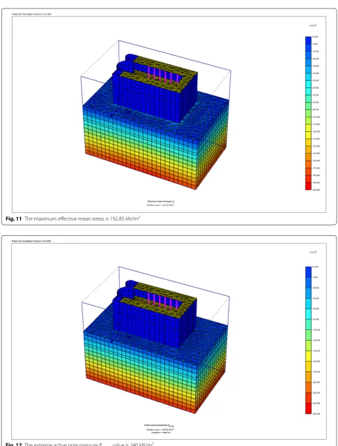
distribution of the subsoil is shown in, with a maximum value of 4.50%. The initial effective compressive stresses was determined at the middle of the clay layer depth, where σv= 60 kN/m2. The effective mean stresses P on
the subsoil is shown below the structure with a maximum value of 192.85 kN/m2, as shown in Fig. 11. The average
effective stress is also calculated and the maximum value is 192.85 kN/m2.
The active pore pressure Pactive distribution in the
ground, where the maximum value of Pactive is 240 kN/m2
as shown in Fig. 12.
Fig. 9 The maximum vertical displacement Uy is 122.85 mm
Fig. 11 The maximum effective mean stress is 192.85 kN/m2
Settlement calculations determined from the empirical study give the same settlement value, Eq. 1 [25];
ΔΗ is the consolidation adjustment, Cc is the compres-sion index, H is the height of the clay soil layer, e0 is the
initial vacuum ratio, P0 is the initial effective vertical
stress in the middle of the mud layer depth, ΔP is the change in the vertical effective stress [26].
where the thickness of layer H is 5.5 m, the compression index Cc = 0.3, the initial stress in the depth of the clay layer is P0= 60 kN/m2. The initial void ratio is 1.84.
The subsidence and settlement of the subsoil may affect seriously the superstructure of the church. The main reasons were the consolidation of subsoil clay lay-ers. Also the shear failure characteristics of subsoil may lead to the ground subsidence. The results of the numer-ical analysis indicated that the distribution of the Uy ver-tical displacement of the church superstructure, with a maximum value of 67.62 mm, and minimum Uy value
(1)
H= CcH
1+e0log
P0+P
P0
�H is the consolidation settlement of the soft clay layer
= (5.5× 0.3)(1 + 1.84) × log10(60+60)/60
= 165 mm.
is 67.62 mm as shown in Fig. 13. While the maximum value of horizontal displacement is 8.91 mm, represent the distribution of the horizontal displacement Ux of the structure of the Abo Serga church, the maximum value of Ux is 8.91 mm and the minimum value of Ux is 2.83 mm.
Figure 14 illustrates the normal axial force N1 on the superstructure of the church; the maximum/minimum principal stresses, the maximum value is 784.85 kN/m and the minimum value is 380.88 kN/m.
The shear force Q1 on the superstructure of the church, is with a maximum value of 305.38 kN/m, and the mini-mum value is 208.96 kN/m as shown in Fig. 15 which represent the maximum/minimum principal stresses.
Figure 16 shows the maximum/minimum principal
stresses, the bending moments of M1 on the superstruc-ture of the church, with a maximum value of 104.88 kN/m and the minimum value is 80.32 kN/m. bending moment 105 kN per length unit is relatively high value, it may be the main cause of the out-plane deformation and the cracks patterns on the main facades of Abu Serga church, and it observed and recorded from the field and experimental studies.
The computed static surface ground displacements under Abu Serga church are in high values: maximum total vertical displacements is 122.85 mm, which is not
Fig. 14 The extreme value of the axial force N1 on the superstructure of the church is 784.85 kN/m
acceptable or permissable. Many researches like [27–32] discussed the permissable maximum settlement for the shallow foundations in clay soils; and indicated that, for the loading bearing walls, the permissible maximum settlement is 60 mm in case of isolated footings, and 125 mm in case of raft foundations.
The maximum normal axial force N1 on the structure is 784.85 kN/m is very close to the uniaial compressive strength of the original brick (1400 kN/m2). Moreover
shear force Q1 is on the superstructure of the church, with a maximum value of 305.38 kN/m, which is also close to the measured shear strength of the rock mate-rial (600 kN/m2). The results also indicated that the
over-stress state is beyond the elastic regime. With a global factor of safety (FoS = strength of component/load on component) equal to 1.78 (< 2) the Abu Serga church should not be considered as safe under static conditions, an FoS of 2 means that a component will fail at twice the design load. In conclusion the detailed analysis of the Abu Serga church proved that these important monu-ments present low safety factors for both static load-ing and soil consolidation settlement. Consequently a well-focused strengthening and retrofitting program is
deemed necessary. It is deemed necessary to upgrade the safety reserves due to the special nature of the structure.
From the results of the numerical modeling, indicated that the structural deficiencies in the superstructure of the oldest Cairo church, mainly the diagonal, shear and vertical cracks and other distortions within the plane, are mainly induced by the differential settlement of the full saturated clay subsoil consolidation.
The technical assessment revealed that almost all level masonry structural walls presented a brittle mode of fail-ure and more than that, from the first level were of “weak and soft stories” type.
Strengthening (restoring) the procedures of the Abu Serga church
The Intervention and strengthening measures and work for the church included the improvement of the sub-soil layers, reinforcement of the shallow foundations and the strengthening of the superstructure the church.
Table 4 summarized the main aspects of structural
strengthening of architectural heritage.
Some details of the strengthening and intervention retrofitting project of Abu Serga church could be given as follow:
1. Improvement of the of soft clay soil with jet injection techniques and liquid normal Portland cement. 2. When the structural elements are capable of taking
care of the total weight of the historical construc-tion structure. Improvement of shallow foundaconstruc-tions found by low pressure injection of hydraulic lime mortar was necessary.
3. It was important to design the stitching system to connect the brick walls to the superstructure ele-ments together.
Extensive grouting was undertaken for filling of the wide cracks across the highly disturbed walls zones penetrating 200–300 mm into the walls. Grouting was carried out prior to the prestressing of the anchors to work load levels.
Our previous experimental study referred that the mix of hydraulic lime + sand + brick dust + small propor-tion of white cement 3:1:1:0.2 respectively gave the best results under the mechanical testing. The hydraulic lime based grouts (due to their improved bond properties with the in situ materials) become more important due to the durability ensured by the use of materials that are com-patible with the existing ones from the physical–chemical point of view [33].
Restoration and improvement the connections between brick walls. To prevent wall cracks in the longi-tudinal direction, reinforce the walls with high-strength strips and insert at least 50 mm in the wall joints in some layers. The number of common layers entered in the ranges was calculated according to the additional tension obtained through the analysis, as shown in Fig. 17. It rec-ommended the inclusion of lead strips with a thickness of about a few millimeters in joints per 1.5–1.5 m above ground to ceiling in double walls. For the stone sections, it should not be isolated. This causes fins to be caused by small, low-magnitude earthquakes, but they are stopped for centuries and prevented from ascending and damag-ing the structure. After the structural reconstruction of the brick walls, it was necessary to reset all surfaces using lime mortar and remove previous interventions using cement paste.
4. Straightening up and reinforcing marble and granite columns with steel ring beams.
5. Stone stitching.
6. Restoration of frescoes and icons. 7. Restoration of timbers.
Figures 18 and 19 illustrate the state of preservation of the church before the strengthening and retrofitting intervention project. Figures 20 and 21 illustrate the strengthening and intervention retrofitting processes and measures which had been done during the restoration project for Abu Serga church.
The present preservation state of the church is pro-vided after the complete installation of remedial meas-ures for therapeutic intervention as shown in Figs. 22 and
23, especially in the cleaning of walls, removal of salt and stitching, and supporting the reinforcement of marble columns with designed steel rings.
Table 4 Aspects of structural strengthening
of architectural heritage
1 Structural interventions related to the foundations (a) Improvement of the ground soil
Bearing soil improvement techniques mainly use the effects of increased adhesion between soil particles, condensation and enhancement to achieve one or more of the following ele-ments: increase strength to improve stability, reduce deforma-tion due to deformadeforma-tion or compression of soil mass, reduce liquefaction and reduce soil natural fluctuations
There are many ways to modify and improve the earth around the world now, including geotextiles, stone columns, micropiles, water dewatering, and pressure, preloading with and without vertical drains, Jet injection, deep mixing, and deep condensa-tion and soil enhancement
Among many ground improvement techniques, the stone column has gained much popularity since it was properly documented in the middle of the last century. Potential applica-tions of stone columns include the stabilization of basic soils, supporting structures, stabilization of the soil, and reduction of soft sanding potential
(b) Improving the behaviour of foundations by enlargement and/ or consolidation
(c) Strengthening of the foundation by underpinning using micro piles isolated or in group or in row
2 Local interventions for structural improvement
(a) Masonry walls Pozzolanic grouting or stitching in cracks. (b) Strengthening roof diaphragms with plywood and steel ties (c) Vertical and Transversal anchorage (Cintec stitching anchors)
in walls
(d) Strengthening masonry columns with jacketing (e.g. FRPs Jacketing like CFRP laminates)
(e) Repair of damaged wood elements 3 Global interventions for structural improvement
(a) Strengthening of masonry walls with reinforced cement coat-ing (shotcrete or jacketcoat-ing)
(b) Strengthening of masonry walls with polypropylene meshing (c) Strengthening of floors and improving the connection floor/
wall
(d) Strengthening of masonry walls with composite materials (CFRP and GFRP)
(e) The use of horizontal tie rods (f ) Retrofitting by post tensioning rodes (g) Strengthening with ring beams (h) Retrofitting by introducing RC shear walls
Fig. 17 The design of the walls stitching and strengthening with different techniques and materials
Conclusions
The assessment of the stability of the ground (bearing soil) and the induced structural deficiency were exam-ined in the Abu Serga church. A three-dimensional FEM model was used to conduct several types of plastic and unit analysis. The long-term structural deformation of the structure has been analyzed over the past centuries
to find an appropriate way to improve and modify it. The numerical model has been calibrated based on the on-site measurement data to determine the correspond-ing model parameters. Different ways of improvcorrespond-ing the parameter have been investigated. It is therefore possi-ble to conclude that modeling soft mud behavior under
Fig. 19 Extensive disintegration and degradation of the bricks walls of the church due to the subsurface water rising
Fig. 20 Abu Serga church’s wall stitching and strengthening
Fig. 21 The strengthening of the structural twelve columns and brick pillars
the Abu Serga script by numerical analysis is appropriate for understanding the geotechnical behavior of the prob-lematic soil type and structural behavior of the structure above it. Various types of soil reinforcement and struc-tural strengthening techniques have been tested to better fit this structure. The results of the analysis indicated that the deteriorated cement plaster layers that covered the interior brick walls during the 1960s should be removed due to its high damage and decay due to the high rise of subsurface water and humidity, as well as the damage to the brick walls due to the consolidation settlement of the bearing soil as well as the geotechnical and structural effect of the earthquakes in particular the Dahshur 1992 and Aqaba 1995 earthquakes.
In conclusion, the detailed analysis of the church of Abu Serga proved that these important Coptic archi-tectural heritages represent low safety factors for both static loading and soil settlement. Accordingly, the existence of a well-focused strengthening and retro-fitting intervention program was very necessary and essential.
Authors’ contributions
The author read and approved the final manuscript.
Acknowledgements Not applicable.
Competing interests
The author declares that he has no competing interests.
Availability of supporting data Not applicable.
Availability of data and materials Not applicable.
Funding
The author confirms that he is not currently in receipt of any research funding relating to the research presented in this manuscript.
Publisher’s Note
Springer Nature remains neutral with regard to jurisdictional claims in pub-lished maps and institutional affiliations.
Received: 17 July 2018 Accepted: 5 February 2019
References
1. Ilies NM, Popa A. Geotechnical problems of historical buildings from Transylavania. In: Bilota A, editor. Geotechnical engineering for the preser-vation of the monuments and historic sites. London: Taylor & Francis Group; 2013.
2. Nasser H, Marawan H, Deck O. Influence of differential settlements on masonry structures. Computat Model Concr Struct. 2014. https ://doi. org/10.1201/b1664 5-93.
3. Müthing N, Zhao C, Hölter R, Schanz T. Settlement prediction for an embankment on soft clay. Comput Geotech. 2018. https ://doi. org/10.1016/j.compg eo.2017.06.002.
4. Brinkgreve RBJ, Engin E, Swolfs MW. Material models manual. Plaxis 3D Plaxis bv, Delft, Netherlands. 2011.
5. Kalai M, Bouassida M, Tabchouche S. Numerical modeling of Tunis soft clay. Geotech Eng J SEAGS AGSSE A. 2015;46(4):87–95.
6. Duncan JM, Chang C. Nonlinear analysis of stress and strain in soils”. J Soil Mech Found Div. 1970;96(SM5):1629–54.
7. Vakili KN, Barciago T, Lavason AA, Schanz J. A practical approach to constitutive models for the analysis of geotechnical problems. In: 3rd international conference on computational geomechanics (ComGeo III), vol 1, Krakow, Poland. 2013.
8. Hemeda S, Pitilakis K. Serapeum temple and the ancient annex daughter library in Alexandria, Egypt: geotechnical–geophysical investigations and stability analysis under static and seismic conditions. Eng Geol. 2010;113:33–43.
9. Hemeda S, Pitilakis K, Bakasis E. Three-dimensional stability analysis of the central rotunda of the catacombs of Kom El-Shoqafa, Alexandria, Egypt. In: 5th international conference in geotechnical earthquake engineering and soil dynamics, May 24–29 2010, San Diego, California, USA.
10. Yamamoto K, Tabata K, Kitamura R. Finite Element Analysis of Seepage and Deformation Properties in Shirasu Ground for the Situations of Sheet Pile Excavation”, Elsevier BV. 2001.
11. Kolymbas D. Constitutive modeling of granular materials. Berlin: Springer; 2017.
12. Di Prisco C, Imposimato S, Aifantis EC. A visco-plastic constitutive model for granular soils modified according to non-local and gradient approaches. Int J Numer Anal Methods Geomech. 2002;26(2):121–38. 13. Carter JP, Booker JR, Wrothu CP. A critical state soil model for cyclic
load-ing. Soil Mech Transient Cyclic Load. 1982;2(1):35–62.
14. Desai CS, Gallagher RH. Mechanics of engineering. London. 1984. 15. Mroz Z, Norris VA, Zienkiewicz OC. An anisotropic critical state model for
soils subjected to cyclic loading. Geotechnique. 1981;31(4):451–5. 16. Provest JH. A simple plastic theory for frictional cohesionless soils. Soil
Dyn Earthq Eng. 1985;4(1):9–11.
17. Iai S, Matsunaga Y, Kaneoka T. Strain space plasticity model for cyclic mobility. Soils Found. 1992;32(2):1–9.
18. Paster M, Zienkiewicz OC, Chan AHC. Generalized plasticity and the modeling of soil behavior. Int J Numer Anal Meth Geomech. 1990;14(1):151–60.
19. Boscato G, Dal Cin A, Riva G, Russo S, Sciarretta F. Knowledge of the construction technique of the multiple leaf masonry façades of palazzo Ducale in Venice with ND and MD tests. Adv Mater Res. 2014;919–921:318–24.
20. Bosiljkov V, Uranjek M, Žarnića R, Bokan-Bosiljkov V. An integrated diag-nostic approach for the assessment of historic masonry structures. J Cult Herit. 2010;11(3):239–49.
21. Hemeda S, Pitilakis K. Geophysical Investigations at Cairo’s Oldest, the Church of Abu Serga (St. Sergius), Cairo, Egypt. Res Nondestruct Eval. 2017;28(3):123–49. https ://doi.org/10.1080/09349 847.2016.11439 91. 22. Hemeda S. Seismic hazard analysis for preservation of architectural
herit-age: the case of the Cairo’s oldest Abu Serga church. Int J Civil Eng Sci. 2014;3:2.
23. Milani G, Valente M, Alessandri C. The narthex of the Church of the Nativ-ity in Bethlehem: a non-linear finite element approach to predict the structural damage. Comput Struct. 2018;207:3–18.
24. Hemeda S. Non-linear static analysis and seismic performance of modern architectural heritage in Egypt. Mediterran Archaeol Archaeometry. 2016;16(3):1–15.
25. Sohan K, Das BM. Principles of geotechnical engineering. 9th ed. Boston: Cengage Learning; 2018.
26. Rajapakse R. Consolidation settlement of foundations. New York: Elsevier; 2016.
27. American Society of Civil Engineers. Guidelines for instrumentation and measurements for monitoring dam performance. Virginia: Reston; 2000. 28. American Society for Testing and Materials, D 2435. Standard test method
for one dimensional consolidation properties of soils. In: American Society for Testing and Materials (ASTM), Vol. 04.08, West Conshohocken, Pennsylvania; 1999. p. 210–9.
29. Das BM. Principles of foundation engineering. 2nd ed. Boston: PWS-KENT Publishing Company; 1990.
30. Fellenius BH. Recent advances in the design of piles for axial loads, dragloads, downdrag, and settlement. Ontario: ASCE and Port of NY&NJ Seminar1, Urkkada Technology Ltd; 1998.
31. Holtz RD, Kovacs WD. Introduction to geotechnical engineering. New Jersey: Prentice Hall Inc., Englewood Cliffs; 1981. p. 309–90.
32. Sitharam TG. Advanced foundation engineering. Bargalore: Indian Insti-tute of Science; 2013.