ORIGINAL ARTICLE
Design and Experimental Research
on Seedling Pick-Up Mechanism of Planetary
Gear Train with Combined Non-circular Gear
Transmission
Yaxin Yu
1,2, Jikun Liu
1,2, Bingliang Ye
1,2*, Gaohong Yu
1,2, Xuejun Jin
1,2, Liang Sun
1,2and Junhua Tong
1,2Abstract
Currently, transplanting mechanisms for dryland plug seedlings in China are mainly semiautomatic and have low efficiency. The rotary seedling pick-up mechanism with a planetary gear train for non-uniform intermittent transmis-sion, and a concave and convex locking arc device, has a large rigid impact. To solve these problems, according to the design requirements for a dryland plug seedling transplanting mechanism, a rotary seedling pick-up mechanism of a planetary gear train with combined circular gear transmission of incomplete eccentric circular and non-circular gears was proposed. This has the characteristics of two-times greater fluctuation of the transmission ratio in a cycle, and can achieve a non-uniform continuous drive. Through analysis of the working principle of the seedling pick-up mechanism, its kinematics model was established. The human–computer interaction optimization method and self-developed computer-aided analysis and optimization software were used to obtain a set of parameters that satisfy the operation requirements of the seedling pick-up mechanism. According to the optimized parameters, the structure of the seedling pick-up mechanism was designed, a virtual prototype of the mechanism was created, and a physical prototype was manufactured. A virtual motion simulation of the mechanism was performed, high-speed photographic kinematics tests were conducted, and the kinematic properties of the physical prototype were investi-gated, whereby the correctness of the theoretical model and the optimized design of the mechanism were verified. Further, laboratory seedling pick-up tests were conducted. The success ratio of seedling pick-up was 93.8% when the seedling pick-up efficiency of the mechanism was 60 plants per minute per row, indicating that the mechanism has a high efficiency and success ratio for seedling pick-up and can be applied to a dryland plug seedling transplanter.
Keywords: Dryland plug seedling transplanter, Rotary seedling pick-up mechanism, Transmission ratio, Non-uniform continuous transmission, Combined non-circular gear transmission, Optimization design
© The Author(s) 2019. This article is distributed under the terms of the Creative Commons Attribution 4.0 International License (http://creat iveco mmons .org/licen ses/by/4.0/), which permits unrestricted use, distribution, and reproduction in any medium, provided you give appropriate credit to the original author(s) and the source, provide a link to the Creative Commons license, and indicate if changes were made.
1 Introduction
The dryland plug seedling transplanter is a type of agri-cultural machinery for transplanting crops such as cul-tivated vegetables and rape plug seedlings into fields. Semiautomatic and automatic transplanting machines have been employed for dryland plug seedling trans-planting in China and other countries. Semiautomatic
transplanters plant seedlings via the planting mecha-nism, and seedling separation and pick-up are completed by hand (“hand-fed”), presenting the problems of con-sider able labor, seedling leakage, and a low transplant-ing efficiency. Automatic transplanters can automatically complete the whole process of transplanting plug seed-lings via mechanical operations with lower labor costs, high transplanting quality, and high efficiency; thus, they have become a development trend [1–5]. The core work-ing part that determines the quality and efficiency of the dryland plug seedling transplanter is the transplanting mechanism. The automatic transplanting mechanism
Open Access
*Correspondence: zist_ybl@zstu.edu.cn
1 College of Machinery and Automation, Zhejiang Sci-Tech University,
Hangzhou 310018, China
being studied in China and other countries generally consists of two mechanisms: seedling planting and seed-ling pick-up. The seedseed-ling-planting mechanism has been significantly developed and is mature, whereas the auto-matic seedling pick-up mechanism is the bottleneck restricting the development of the automatic transplanter and has become a popular and challenging research topic throughout the world.
The Japanese researchers Naokatsu et al. [6] devel-oped a gear-link combined seedling pick-up mechanism consisting of a planetary gear train and a crank-slide mechanism that has a low seedling pick-up efficiency of approximately 50 plants per minute per row, a complex structure, and a slideway that is prone to wear. Korean Choi et al. [7] designed a vegetable plug seedling pick-up mechanism of the crank-guide rod-slideway type composed of five rods, seedling pick-up claws, and their respective drives. It has a relatively simple structure, but the seedling pick-up efficiency is low (only 30 plants per minute), the slideway is prone to wear, and signifi-cant vibration occurs during operation. The American researcher Shaw [8] designed an ejection-type seedling pick-up mechanism that could remove seedlings from tray cells through cell drain holes at the bottom of the tray cells via pneumatic ejectors. It has high transplanting efficiency and is suitable for transplanting seedlings to large fields in Europe and the United States. However, the machine has a complex structure and expensive. Thus, it is difficult to fully apply in China [9, 10]. In China, it is not long to study on automatic dryland seedling pick-up mechanism that has been rarely applied. Xu et al. [11] proposed a planar four-bar mechanism for seed-ling pick-up. The trajectory with sharp tips on its two ends is effective for seedling pick up, but the efficiency of the mechanism is low, and the location of the falling seedlings is not ideal. Zhang et al. [12] designed an auto-matic transplanting manipulator with three cylinders to control seedling pick-up and delivery using a program-mable logic controller. This is suitable for transplanting plug seedlings between trays on two conveyer belts, but not suitable for mechanical transplanting operations in fields. Hui [13] developed an automatic seedling pick-up mechanism with a crank and double sliders that was suit-able for tobacco plug seedlings. However, the slideway is prone to wear, and the machine has significant vibrations and creates shock. Cui et al. [14] designed a combined-type seedling pick-up mechanism with a gear and five bars consisting of a gear box, a crank, a link, a seedling pick-up arm, and seedling pick-up claws. Because the inertial force of the linkage mechanism cannot be com-pletely balanced, the seedling pick-up efficiency is low.
In recent years, Refs. [15–25] of the Agricultural Machinery Institute of Zhejiang Sci-Tech University in
China have proposed three types of automatic rotary seedling pick-up mechanisms composed of a planetary gear train and seedling pick-up arms, which work sta-bly and efficiently. The aim of this work was to solve the problems of seedling pick-up mechanisms, such as the complex structures, high costs, low efficiency of seedling pick-up, large vibration during operation, and unsuit-ability for transplanting plug seedlings in China. In this system, two seedling pick-up arms are arranged symmet-rically on the rotary box, and two seedlings are extracted in a working cycle. Yu et al. proposed a rotary seedling pick-up mechanism with an elliptical gear, incomplete cylindrical gear transmission, and a concave and con-vex locking device. To simplify the mechanism, Yu et al. proposed a rotary seedling pick-up mechanism with an elliptical gear and incomplete non-circular gear transmis-sion, as well as a concave and convex locking arc device. These two seedling pick-up mechanisms can achieve the requirements of non-uniform intermittent transmission and trajectory of seedling pick-up, but a rigid impact occurs when the convex and concave locking arcs of the mechanism enter and disengage meshing, which affects the success ratio and speed of seedling pick-up. Zhao et al. proposed a rotary seedling pick-up mechanism with non-uniform continuous transmission of the plan-etary gear train using two-order general non-circular gears. However, the transmission ratio of the planetary gear train with the two-order general non-circular gears in the seedling pick-up mechanism can achieve only a two-times small fluctuation in a period, and the ratio of the two peaks is only 1.8. Neither the depth of seedling pick-up nor the posture of seedling pushing are ideal, it is necessary to design a larger-force arm, and the dynam-ics performance is insufficient. In this paper, a new type of rotary plug seedling pick-up mechanism is proposed. It consists of a planetary gear train with combined non-circular gear transmission of incomplete eccentric circu-lar and non-circucircu-lar gears that can achieve non-uniform continuous transmission with kinematic characteristics of two-times greater fluctuation of the transmission ratio in a cycle. Studies on the seedling pick-up mechanism were performed, including kinematics modeling and analysis, structure design, virtual motion simulation, pro-totype tests, and seedling pick-up tests.
2 Design Requirements of Rotary Seedling Pick‑Up Mechanism
ratio, and high seedling-standing ratio. In operation, the rotary seedling pick-up mechanism extracts plug seed-lings from the seedling tray and places them into the duckbill-type planting mouth after the process of seed-ling carrying and pushing. Then, the seedseed-lings fall into holes, which are opened by the planting mouth, while compaction wheels cover them with soil.
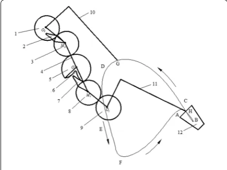
The rotary plug seedling pick-up mechanism is the core part of the automatic transplanting machine, includ-ing the transmission part of the planetary gear mecha-nism and the executive part of the seedling pick-up arm. Seedling pick-up needles on the seedling pick-up arm comprise the execution end of the mechanism, and the cusp trajectory and posture of the seedling pick-up arm directly affect quality of seedling pick-up and pushing. According to comprehensive analysis of many types of seedling pick-up trajectories and the requirements of the seedling pick-up arm posture, the seedling pick-up trajectory ABCDEFA shown in Figure 1(a), which is the motion trajectory formed by the cusp of the seedling pick-up arm, is proposed.
The trajectory can be divided into four parts corre-sponding to four working processes: seedling pick-up, seedling transportation, seedling pushing, and return stroke. (1) Trajectory ABC of seedling pick-up. Seedling pick-up needles are inserted into the seedling tray and slowly clamp the plug seedling. When the needles reach point B, the seedling is completely clamped. It is then extracted approximately perpendicular to the seedling tray. (2) Trajectory CDE of seedling transportation. The extracted seedling is transported to the seedling push-ing position. (3) Trajectory EF of seedling pushing. The seedling pushing rod moves toward the cusp and drives the needles open; then, the seedling falls into the planting mouth of the planting mechanism. (4) Trajectory FA of return stoke. The seedling pick-up mechanism returns to the initial position for the next operation cycle.
The seedling pick-up mechanism completes four suc-cessive procedures of seedling pick-up, seedling trans-portation, seedling pushing, and return stroke in a cycle, and the seedling pick-up trajectory should form a slen-der ring. To avoid motion interference between the nee-dles and the seedling tray, the inner concave trajectory of the needles should be formed before they enter the tray. During the process of the seedling needles entering and leaving the seedling bowl tray, the needles should move very little. That is, the width of the ring should be as small as possible to prevent damage to the plug seedlings. The needles should leave perpendicular to the tray. When the seedling is pushed, the seedling-pushing angle should be sufficiently large for the seedling to fall into the planting mechanism with good gesture.
3 Kinematic Analysis of Rotary Seedling Pick‑Up Mechanism
3.1 Structure and Working Principle of Seedling Pick‑Up Mechanism
According to the design requirements of the rotary seed-ling pick-up mechanism, a new type of rotary seedseed-ling pick-up mechanism involving a planetary gear train with Figure 1 Scheme of the automatic transplanting operation
combined non-circular gear transmission of incomplete eccentric circular and non-circular gears was proposed, as shown in Figure 1(a). The seedling pick-up mecha-nism consists of two planetary non-circular gears (1, 9), two middle gears (non-circular gear 3 and incomplete non-circular gear 2, non-circular gear 8 and incomplete non-circular gear 7), a planetary carrier (4), a sun gear (incomplete eccentric circular gear 5 and incomplete non-circular gear 6), and two seedling pick-up arms (10, 11). The sun gear and middle gears employ combined non-circular gear transmission with incomplete eccen-tric circular and non-circular gears; thus, non-uniform motion and continuous transmission can be achieved. After the optimization design of the mechanism is com-plete, the transmission ratio exhibits two times fluctua-tion continuously and sharply, and the double-peak ratio is 5.56 [26].
The seedling pick-up mechanism is centro symmetric with the sun gear. The underside structure shown in Fig-ure 1(a) is considered as an example to analyze the work-ing principle of the mechanism. O is the rotation center of the planetary carrier, M1 and M2 are the rotation cent-ers of the middle gears, and O1 and O2 are the rotation centers of the planetary gears. The curve ABCDEF is the motion trajectory of the cusp of the seedling pick-up arm.
During the operation of the seedling pick-up mecha-nism, the sun gear is fixed, and the planetary carrier rotates counterclockwise with a uniform speed around point O, driven by the central axis. The alternate mesh-ing of two gear pairs in the combined non-circular gear transmission achieves a non-uniform continuous drive with two-times greater amplitude fluctuation of the transmission ratio in a cycle. The combined middle gear consisting of incomplete circular gear 7 and non-circular gear 8 rotates around point O, along with the planetary carrier, and also revolves counterclockwise around the rotation center M2 on the planetary carrier. Similarly, when the planetary non-circular gear 9 rotates around rotation center O along with the planetary car-rier, it rotates clockwise around the rotation center O2. The seedling pick-up arm is fixed on the planetary gear through the planetary gear axle. After the parameters of the mechanism are optimized, the cusp of the seedling pick-up arm forms a motion trajectory, as shown in Fig-ure 2(a), under the effect of two types of motions.
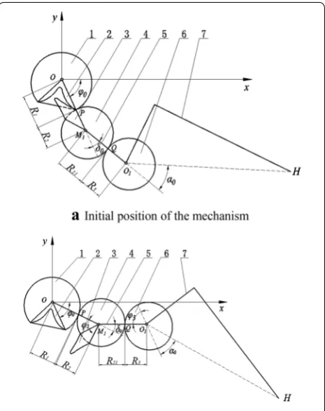
3.2 Kinematics Model of Seedling Pick‑Up Mechanism The kinematics model of the seedling pick-up mechanism was established by considering one side of the mecha-nism as an example [27–31]. The motion diagram of the seedling pick-up mechanism is shown in Figure 2, and the rectangular coordinate system Oxy was established.
Points O, M1, and O1 are the rotation centers of the plan-etary carrier, the middle gear, and the planplan-etary gear, respectively. Point H is the cusp of the seedling pick-up arm. Points P and Q are the meshing points between the middle gear and the sun gear and between the middle gear and the planetary gear, respectively. φ0 is the initial installation angle of the seedling pick-up mechanism, δ0 is the planetary carrier corner (acute angle between lines M1O and M1O1), and α0 is the installation angle of the seedling pick-up arm. β is the central angle of the pitch curve of the toothed part of the incomplete eccentric cir-cular gear. α is the center angle corresponding to the par-tial pitch curve of the middle non-circular gear meshing with the incomplete eccentric circular gear. θ is the initial rotation angle of the incomplete eccentric circular gear. R1 and R2 are the distances from the meshing point P between the sun gear and the middle gear to the rotation centers O and M1, respectively. R′1 and R′2 are the radius vectors of the meshing pitch curves of the incomplete non-circular gears 2 and 3, respectively. R21 and R3 are distances from the meshing point Q between the middle
gear and the planetary gear to rotation centers M1 and
O1, respectively.
3.2.1 Displacement Model of Seedling Pick‑Up Mechanism
When the planetary carrier rotates counterclockwise by the angle ϕ1 from the initial position of the mechanism shown in Figure 2(a), the rotation angles of the middle gear and the planetary gear relative to the planetary car-rier are ϕ2 and ϕ3 , respectively, as shown in Figure 2(b).
(1) Angular-displacement analysis of the middle gear rel-ative to the planetary carrier
The drive of the middle gear and the sun gear is a com-bined non-circular gear transmission. The transmission of the two pairs of gears should satisfy the requirement that the pitch-curve perimeters of the meshing parts are equal during meshing. Then, the analysis and solution of the angular displacement of the middle gear relative to the planetary carrier can be divided to two cases.
When the planetary carrier rotates by the angle ϕ1 from
− ϕ0 to β −ϕ0 , the middle non-circular gear 4 meshes
with the incomplete eccentric circular gear 1. Thus, the following equation is obtained:
where
Here, R and e represent the radius and eccentric dis-tance, respectively, of the incomplete eccentric circle, and L represents the center distance between the middle gear and the sun gear.
Using Eqs. (1) and (3), the following equation is obtained:
According to Eq. (4), the center distance L is calculated using numerical integration after the parameters β, α, R, e, and θ are determined.
To ensure the completeness of the middle non-circular gear and the smoothness and continuity of the periodic pitch curve, the pitch-curve equation for the middle non-circular gear 4 that does not mesh with the sun gear is
(1) ϕ2 =
ϕ1
−ϕ0 R1(ϕ1)
R2(ϕ2) dϕ1,
(2) R1(ϕ1)=ecos(ϕ1+θ )+
R2−e2sin2(ϕ 1+θ ),
(3) R2(ϕ2)=L−R1(ϕ1).
(4)
α= β−ϕ0
−ϕ0
R1(ϕ1) L−R1(ϕ1)
dϕ1.
(5)
R2(ϕ2) = b0+b1ϕ2+b2ϕ22+ b3ϕ23, α≤ϕ2≤2π.
In summary, the pitch-curve equation for the middle non-circular gear is
In Eq. (6), the coefficients b0, b1, b2, and b3 are calcu-lated according to the requirements of the smoothness and continuity of the periodic pitch curve of the middle non-circular gear.
When the planetary carrier rotates by the angle ϕ1 from β −ϕ0 to 2π −ϕ0 , the incomplete non-circular gears 2 and
3 mesh with each other, and the following equation is obtained:
where R′
2(ϕ2)=L−R′1(ϕ1).
The transmission-ratio function of the incomplete non-circular gears 2 and 3 is
Here, the transmission-ratio function is constructed as follows:
In Eq. (9), the transmission-ratio coefficients a1, a2 and
a3 can be determined according to the continuity condi-tion of the transmission ratio of the two pairs of gears.
According to Eqs. (8) and (9), the pitch-curve equation for the transmission of the incomplete non-circular gears 2 and 3 is
(2) Angular-displacement analysis of the planetary gear relative to the planetary carrier
When the middle gear meshes with the planetary gear, the two gears should satisfy the requirement that the pitch-curve perimeters of their meshing parts are equal. Then, the following equation is obtained:
where
(6) R2(ϕ2)=
L−R1(ϕ1), −ϕ0≤ϕ1≤β−ϕ0, b0+b1ϕ2+b2ϕ22+b3ϕ32, α≤ϕ2≤2π.
(7)
ϕ2= ϕ1
β−ϕ0 R′
1(ϕ1)
R′
2(ϕ2) dϕ1,
(8) i2(ϕ1)= R
′ 2(ϕ2) R′
1(ϕ1) .
(9)
i2(ϕ1)=a0+a1sinϕ1+a2cosϕ1.
(10) R′ 1=
Li2(ϕ1) 1+i2(ϕ1)
,
R′2=
L
1+i2(ϕ1) . (11) ϕ3= ϕ2 0 R21(ϕ1)
R3(ϕ3)dϕ2,
Here, a is the distance between the centers of the mid-dle gear and the planetary gear.
When the planetary carrier rotates by the angle ϕ1 from zero to 2π, the middle gear and the planetary gear corre-spondingly rotate by the angles ϕ2 and ϕ3 , respectively, from zero to 2π. Thus, the following equation is obtained:
R21(ϕ1) can be approximately calculated using R2(ϕ2) according to the equations below Eq. (11). The distance a between the centers of the middle gear and the planetary gear can be calculated using the numerical-integration method according to Eq. (12) [23]. After R21(ϕ1) and a are calculated, ϕ3 can be calculated using Eq. (11).
The relative displacement of the cusp H of the seedling pick-up arm is
where S is the distance from the cusp of the seedling pick-up arm to the rotation center of the planetary gear.
3.2.2 Velocity Model of Seedling Pick‑Up Mechanism
The planetary carrier rotates counterclockwise with a uniform angular speed ω1. The angular speed of the plan-etary non-circular gear relative to the planplan-etary carrier is
The relative velocity of the cusp H of the seedling pick-up arm can be obtained by taking the derivative of Eq. (13):
The resultant relative velocity of the cusp H of the seed-ling pick-up arm is
4 Optimization Design of Rotary Seedling Pick‑Up Mechanism
To optimize the parameters of the rotary seedling pick-up mechanism for dryland plug seedlings, which is a fuzzy, nonlinear, strong-coupling, and complex optimization problem, the following steps were taken. An optimization
(12) 2π=
2π
0
R21
a−R21dϕ2.
(13)
XH =Lcos(ϕ0+ϕ1)+acos(ϕ0+ϕ1+δ0)
+Scos(ϕ0+ϕ1+δ0+α0+ϕ3),
YH =Lsin(ϕ0+ϕ1)+asin(ϕ0+ϕ1+δ0)
+Ssin(ϕ0+ϕ1+δ0+α0+ϕ3),
(14)
ω3=
R1 R2
R21 R3ω1.
(15)
vHx= −ω1Lsin(ϕ0+ϕ1)−aω1sin(ϕ0+ϕ1+δ0) −S(ω1+ω3)sin(ϕ0+ϕ1+δ0+α0+ϕ3), vHy=ω1Lcos(ϕ0+ϕ1)+aω1cos(ϕ0+ϕ1+δ0)
+S(ω1+ω3)cos(ϕ0+ϕ1+δ0+α0+ϕ3).
(16) vH =
vHx2 +v2Hy.
design model of the seedling pick-up mechanism was constructed, computer-aided analysis and optimization software for the mechanism was developed, and param-eter optimization of the mechanism was finally realized by using the human–computer interaction optimization method [32].
4.1 Optimization Objectives and Design Variables of Seedling Pick‑Up Mechanism
According to previous research and consideration of the physical properties of dryland plug seedlings, the pos-ture of the seedling pick-up arm, the motion interference, the motion trajectory, and the structure of the mecha-nism, the optimization objectives of the seedling pick-up mechanism were determined as follows:
1) There should be no motion interference between the two seedling pick-up arms or between the arms and the plug seedling tray.
2) The seedling pick-up trajectory should form a slender ring. The width of the ring should be less than 5 mm, and the length of the seedling pick-up trajectory in the tray should be approximately 30 mm.
3) The posture of the seedling pick-up arm should be appropriate. The trajectory of the seedling pick-up section should be approximately perpendicular to the plug seedling tray, and the seedling-pushing angle should be greater than 50°.
4) The mechanism should be compact, such that the rotation radius of the gearbox is less than 150 mm.
Through kinematic analysis of the seedling pick-up mechanism, the following design variables were selected: the radius and eccentric distance of the incomplete eccentric circle R and e, respectively; the central angle corresponding to the pitch curve of the toothed part of the incomplete eccentric circular gear β; the central angle corresponding to the pitch curve of the meshing part of the middle non-circular gear with the incomplete eccentric circular gear α; the initial rotation angle of the incomplete eccentric circle θ; the initial installation angle of the seedling pick-up mechanism ϕ0 ; the installation
angle of the seedling pick-up arm α0 ; the corner angle
of the planetary carrier δ0 ; and the distance between the
cusp of the seedling pick-up arm and the rotation center of the planetary gear S.
4.2 Analysis of Parameter‑Optimization Results for Seedling Pick‑Up Mechanism
was developed, and its main interface is shown in Fig-ure 3. By using the software to input or adjust the param-eters of the mechanism, motion simulation and velocity analysis of the seedling pick-up mechanism were per-formed, and the motion interference was checked. The influence of the design variables on the mechanism tra-jectory was analyzed. The tooth profile of the non-circu-lar gear was designed. Real-time outputs of the motion trajectory, the seedling pick-up angle, the seedling-push-ing angle, and the difference between these angles were obtained.
According to analysis of the influence of each design parameter on the kinematic trajectory, a set of param-eters that satisfy the requirements of seedling pick-up were obtained: R = 28 mm, e = 3.3 mm, β = 288°, α = 323°, θ = 30°, ϕ0= 65°, α0= 36°, δ0= 26°, and S = 152 mm. The
center distance of the gear drive was L = 51.68 mm and a = 48.12 mm.
After parameter optimization of the mechanism, the motion trajectory of the mechanism was obtained, as shown in Figure 4. The trajectory of the seedling pick-up section forms a slender ring whose width is 1.9 mm. The trajectory of the seedling pick-up section is nearly per-pendicular to plug seedling tray, and the trajectory length in the seedling tray is 30.4 mm. The seedling pushing angle is approximately 52°, and the rotation radius of the gearbox is approximately 118 mm. Relative-motion simu-lation of the seedling pick-up mechanism indicates that
there is no motion interference between the two arms or between the seedling pick-up arm and the seedling tray during the operation of the mechanism. The optimiza-tion results satisfy the requirements of the optimizaoptimiza-tion objectives, and the optimized seedling pick-up mecha-nism satisfies the requirements for transplanting plug seedlings.
Figure 3 Main interface of the human–computer interaction-aided analysis and optimization software used for the design of the seedling pick-up mechanism: 1. Menu area; 2. Graphic-display area; 3. Parameter-input area; 4. Result-output area
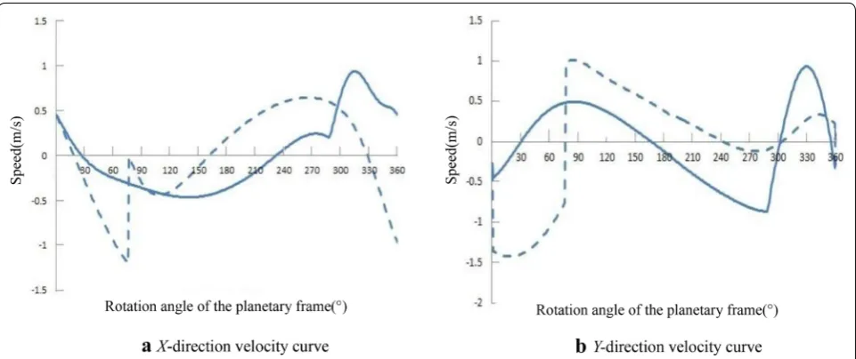
As shown in Figure 5, the velocity curve of the cusp of the seedling pick-up arm for the seedling pick-up mecha-nism designed in this study was compared with that of a previously reported seedling pick-up mechanism with a locking arc device [30]. The dotted and solid lines rep-resent the velocity curves of the previous and proposed seedling pick-up mechanisms, respectively. For the origi-nal mechanism, when the rotation angle of the planetary carrier is 0° and 77°, the X- and Y-direction velocities both change suddenly.
When the rotation angle of the planetary carrier is 0°, the concave and convex locking arcs begin meshing, the X-direction velocity changes from − 0.96 to 0.42 m/s, and the Y-direction velocity changes from − 0.38 to − 1.36 m/s. When the rotation angle of the planetary carrier is 77°, the concave and convex locking arcs fin-ish meshing, the X-direction velocity changes from − 1.2 to − 0.01 m/s, and the Y-direction velocity changes from − 0.76 to 0.98 m/s. The results indicate that the cusp velocity of the seedling pick-up arm of the original mechanism changes at the moments when the concave and convex locking arc enters and departs meshing, lead-ing to a rigid impact on the original mechanism, which affects the operation stability. For the proposed seedling pick-up mechanism, there are no such changes in the velocity curves, indicating that this mechanism has no impact and runs smoothly, which is beneficial for the transplanting performance.
5 Virtual Simulation and Tests of Rotary Seedling Pick‑Up Mechanism
5.1 Virtual Simulation of Seedling Pick‑Up Mechanism According to the optimized parameters, the structure of the seedling pick-up mechanism was designed. Three-dimensional modeling and virtual assembly of the seed-ling pick-up mechanism were performed using the UG software, and then assembly model was imported into ADAMS to conduct a motion simulation for the mech-anism. The motion trajectory and velocity curves of the cusp of the seedling pick-up arm of the mechanism were obtained and compared with theoretical results calcu-lated using optimization analysis software, which verified the correctness of the theoretical model and the design results for the seedling pick-up mechanism. The virtual prototype of the seedling pick-up mechanism is shown in Figure 6.
Figure 5 Velocity-curve comparison of the cusp of the seedling pick-up arm for different seedling pick-up mechanisms
5.1.1 Trajectory Analysis of Seedling Pick‑Up Mechanism
The trajectories of the mechanism in the theoretical analysis and the virtual simulation are shown in Figure 7. In the theoretical analysis, the trajectory was obtained through the optimization analysis software. As shown in Figure 7(a), the length and width of the ring of the seedling pick-up trajectory were approximately 25 and 1.9 mm, respectively, and the height of the seedling pick-up trajectory was approximately 187 mm.
In the virtual simulation, the trajectory was obtained through motion simulation of the virtual prototype. As shown in Figure 7(b), the length and width of the ring of the seedling pick-up trajectory were approximately 25 and 2.3 mm, respectively, and the height of the seedling pick-up trajectory was approximately 167 mm.
Figure 7 indicates that the trajectories of the theoretical analysis and virtual simulation are similar, but there are slight differences in the trajectory height and the return-section trajectory EFA. For this reason, in the combined non-circular gear transmission, the tooth profiles of the incomplete non-circular gears (sun gear and middle gear) were designed as a similar profiles of cams, and the trans-mission ratio of the mechanism became smaller. Addi-tionally, the pitch curve had a small surplus after it was arranged with 21 teeth; thus, the remaining pitch curve was arranged in the incomplete non-circular gear in the sun gear, which caused the seedling pick-up mechanism to begin the return procedure earlier than in the previous design. However, these factors do not affect the perfor-mance of the seedling pick-up mechanism, because the operation of seedling pushing is completed before the mechanism enters the return procedure, as indicated by the simulation test.
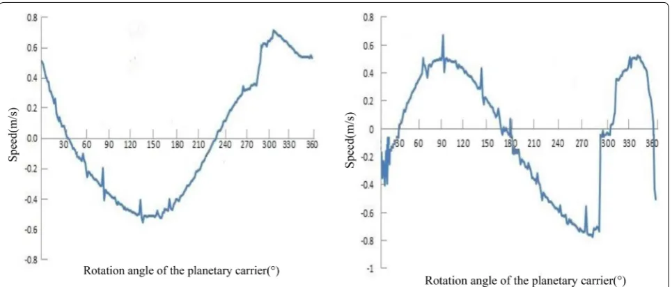
5.1.2 Velocity Analysis of Seedling Pick‑Up Mechanism
The velocity curves of the theoretical calculation and simulation analysis are shown in Figures 8 and 9, respec-tively, for a planetary-carrier rotation speed of 60 r/min. Figure 8(a) and (b) show the X- and Y-direction velocity
curves for the theoretical calculation, respectively, and Figure 9(a) and (b) show the X- and Y-direction velocity curves for the virtual simulation, respectively.
The velocity curves for the simulation analysis and the theoretical calculation are essentially the same. However, a slight difference is observed: when the planetary car-rier rotates from 280° to 360°, there is a wave peak in the X- and Y-direction velocity curves, and the peak value in Figure 8(a) and (b) is larger than that in Figure 9(a) and (b). The reason for this is the same as that for the trajec-tory difference.
5.2 Kinematics Tests of Seedling Pick‑Up Mechanism According to the structure design of the seedling pick-up mechanism, non-circular gears were processed via wire-cutting and heat-treatment technology. Aluminum alloy parts, including a gearbox, were manufactured in a Figure 7 Trajectory comparison for the seedling pick-up mechanism
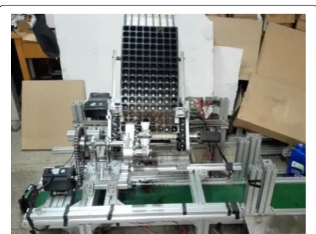
machining center, and then the parts were assembled into a physical prototype of the seedling pick-up mechanism. The mechanism prototype was installed on a self-made test bench to conduct kinematics tests using high-speed photography technology. Figure 10 shows the high-speed camera (Phantom v5.1) used in the kinematics experi-ments. This camera can obtain high-speed photographs with millions of pixels and is produced by the American VAI Company. It provides high image quality, resolution, and sensitivity. The experimental process was as follows. First, a distinctive marker was placed at the tip of the picking claw. Then, the high-speed camera was installed at a suitable position so that the pick-up mechanism could be displayed on the screen during operation. The
position and intensity of the light were adjusted to make the marked points clearly visible. The capture rate was set as 370 fps. The speed of the drive motor was adjusted to 60 r/min. After the machine operated smoothly, the image acquisition began. Finally, Blaster’s MAS image analysis software was used to process and analyze the collected images, and the motion trajectory of the tips of the seedling claws was obtained. The motion trajectory is shown in Figure 11.
Comparing the trajectories of the high-speed photogra-phy and virtual simulation shown in Figures 11 and 7(b), respectively, reveals the following differences. For the real trajectory, the angle of seedling pushing at the end of the pushing operation was 47°, which is slightly smaller than Figure 9 Simulated velocity curves
that of the theoretical analysis (50°). The height of the real trajectory was slightly lower than that of the theoretical trajectory.
The main factors affecting the seedling-pushing angle are machining and installation errors and the clearance of the gear profile. In the combined incomplete non-circular gear transmission of this mechanism, a pair of gears employ cam-like transmission. The contours of the incomplete non-circular gears were obtained via a graph-ical method. For avoiding interference, the actual pitch curve of the incomplete non-circular gears was lower than the theoretical pitch curve, reducing the height of the actual seedling trajectory.
During the operation of the prototype, the seedling pick-up mechanism rotated stably, and there was no motion interference, indicating the effectiveness of the design of the novel seedling pick-up mechanism.
5.3 Seedling Pick‑Up Tests of Proposed Mechanism
A plug tray with 8 × 16 cells and cordate houttuynia seedlings were employed for the tests, as shown in Fig-ure 12. The mechanism prototype was installed on the
self-developed test bench shown in Figure 13, and the rotation speeds of the motor were set as 30, 40, and 50 r/ min. In each test, 128 seedlings were extracted. The high-speed camera was used to observe the operation of the seedling pick-up mechanism. The number of seedlings successfully extracted was recorded, and the success ratio was calculated.
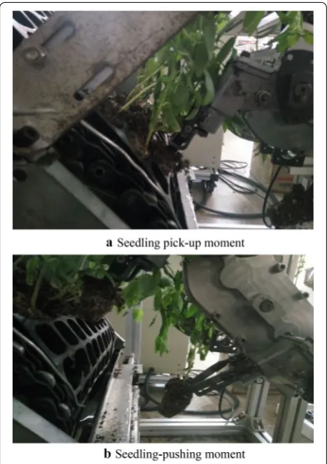
The seedling pick-up and pushing moments are shown in Figure 14(a) and (b), respectively, and the seedling pick-up test results are presented in Table 1. The data in the table indicate that when the rotation speed was 30 r/ min (seedling pick-up efficiency of 60 plants per minute for a single row), the success ratio of seedling pick-up was 93.8%. Thus, the optimized mechanism can be used in a dryland plug seedling transplanter. As the rotation speed of the mechanism increased, the success ratio of seedling up decreased. The main reasons for seedling pick-up failure were the seedlings being too tall and the sub-strates of the bowl being too dry and loose and thus easily broken.
6 Conclusions
(1) According to the mechanical transplanting require-ments for dryland seedlings, a new type of rotary seedling pick-up mechanism employing a planetary gear train with combined non-circular gear trans-mission of incomplete eccentric circular and non-circular gears that can realize non-uniform con-tinuous transmission was proposed. The working principle of the seedling pick-up mechanism was studied, a kinematics analysis of the mechanism was performed, and a kinematics model was estab-lished.
(2) The human–computer interaction optimization method was used to obtain the optimal design of the seedling pick-up mechanism. The follow-ing set of parameters of the mechanism satisfyfollow-ing the working requirements of mechanical pick-up for dryland seedlings were optimized: the radius
Figure 12 Plug tray and Cordate houttuynia seedlings used for the tests
and eccentric distance of the incomplete eccentric circular gear (R = 28 mm and e = 3.3 mm, respec-tively), the central angle corresponding to the pitch curve of the toothed part of the incomplete eccen-tric circular gear β = 288°, the central angle corre-sponding to the pitch curve of the meshing part of the middle non-circular gear with the incomplete eccentric circular gear α = 323°, the initial rota-tion angle of the incomplete eccentric circular gear
θ = 30°, the initial installation angle of the seed-ling pick-up mechanism ϕ0= 65°, the installation
angle of the seedling pick-up arm α0= 36°, the
cor-ner angle of the planetary carrier δ0= 26°, and the
distance between the cusp of the seedling pick-up arm and the rotation center of the planetary gear
S = 152 mm. The distance between the centers of the two pairs of gears driving the seedling pick-up mechanism was L = 51.68 mm and a = 48.12 mm. The kinematics model and optimization design of the seedling pick-up mechanism were verified though a virtual simulation of the mechanism. (3) High-speed photography kinematics tests and
seedling pick-up tests were conducted to study the motion characteristics of the mechanism prototype and to verify its seedling pick-up effect. The success ratio of seedling pick-up was 93.8% when the seed-ling pick-up efficiency of the mechanism was 60 plants per minute per row, indicating that the novel mechanism can be applied to dryland plug seedling transplanters.
Authors’ Contributions
BY was in charge of the whole trial; YY and JL wrote the manuscript; GY, XJ, LS and JT assisted with experiments and data analysis. All authors read and approved the final manuscript.
Author Details
1 College of Machinery and Automation, Zhejiang Sci-Tech University,
Hangzhou 310018, China. 2 Zhejiang Province Key Laboratory of Transplanting
Equipment and Technology, Hangzhou 310018, China.
Authors’ Information
Yaxin Yu, is currently an associate professor and a master’s supervisor at Key Laboratory of Transplanting Equipment and Technology, Zhejiang Sci-Tech University, China. Her main research interests include mechanical design and mechanical dynamics.
Jikun Liu, is currently a master candidate at Key Laboratory of Transplanting Equipment and Technology of Zhejiang Sci-Tech University, China.
Bingliang Ye, is currently a professor and a PhD candidate supervisor at Key Laboratory of Transplanting Equipment and Technology, Zhejiang Sci-Tech University, China. His main research interests include agricultural machinery innovation design, mechanism kinematics and dynamics and mechanical optimization design.
Gaohong Yu, is currently a professor and a PhD candidate supervisor at Key Laboratory of Transplanting Equipment and Technology, Zhejiang Sci-Tech University, China. His main research interests include agricultural machinery innovation design, mechanism kinematics and dynamics and mechanical optimization design.
Xuejun Jin, received his master degree from Zhejiang Sci-Tech University, China, in 2017.
Liang Sun, is currently an associate professor and a master’s Supervisor at Key Laboratory of Transplanting Equipment and Technology, Zhejiang Sci-Tech University, China. His main research interests include mechanism synthesis, mechanical simulation technology and agricultural machinery.
Junhua Tong, is currently a lecturer at Key Laboratory of Transplanting Equip-ment and Technology, Zhejiang Sci-Tech University, China. His main research interests include mechanism synthesis, mechanical simulation technology and agricultural machinery.
Funding
Supported by National Key Research and Development Program of China (Project No. 2017YFD0700800), Zhejiang Provincial Natural Science Founda-tion of China (Grant No. LZ16E050003), Natural Science FoundaFounda-tion of China Figure 14 Seedling pick-up tests
Table 1 Results of the seedling pick‑up test Rotation
speed (r/ min)
Total number of seedlings (plant)
Number of seedlings successfully extracted (plant)
Success ratio of seedling pick‑up (%)
30 128 120 93.8
40 128 112 87.5
(Grant No. 51505429), and Science Foundation of Zhejiang Sci-Tech University (Grant No. 15022011-Y).
Competing Interests
The authors declare that they have no competing interests.
Received: 6 June 2018 Accepted: 19 April 2019
References
[1] Z J Lv, Y Y Shan, J Wang, et al. Research progress of vegetable transplant-ing machine and prospects of seedltransplant-ing picktransplant-ing machinery of trans-planter. Journal of Chinese Agricultural Mechanization, 2017, 38(11): 30–34. (in Chinese).
[2] H Y Zhou, B N Yang, H Yan, et al. Status quo and development prospects of dry land transplanting machine industry. Agricultural Engineering, 2015, 5(1): 12–13. (in Chinese).
[3] J Wang, D D Du, J B Hu, et al. Vegetable mechanized harvesting technol-ogy and its development. Transactions of the Chinese Society for Agricul-tural Machinery, 2014, 45(2): 81–87. (in Chinese).
[4] X X Yu, Y Zhao, B C Chen, et al. Current situation and prospect of trans-planter. Transactions of the Chinese Society for Agricultural Machinery, 2014, 45(8): 44–53. (in Chinese).
[5] Kumar G V Prasanna, Raheman H. Vegetable transplanters for use in developing countries-a review. International Journal Vegetable Science, 2008, 14(3): 232–255.
[6] T Konosuke. Development of fully automatic vegetable transplanter. Japan Agricultural Research Quarterly, 2000, 34(1): 21–28.
[7] W C Choi, D C Kim, I H Ryu, et al. Development of seedling pick-up device for vegetable transplanters. ASAE, 2001, 45(1): 13–19.
[8] L N Shaw. Automatic transplanter for vegetables. Proceedings of Florida State Horticultural Society, 1997, 110: 262–263.
[9] Xiang, M L Wu, Y J Xu. Present status and prospects of seedling trans-planting machinery. Journal of Agricultural Mechanization Research, 2015, 37(8): 6–9, 19. (in Chinese).
[10] X B Yuan, G F Zhang, J N Chen, et al. Development on rice plotted-Seed-ling sequential transplanter. Journal of Zhejiang Sci-Tech University, 2011, 28(5): 749–753. (in Chinese).
[11] L M Xu, T Z Zhang, Z Q Shi. Design on the picking seedling machinery in the maize auto transplanter. Journal of China Agricultural University, 2000, 5(4): 58–60. (in Chinese).
[12] S Zhang, S B Tian, L C Qiu, et al. Structure design and simulation on manipulator of transplanting potted tray seedlings. Journal of Shenyang Agricultural University, 2007, 38(3): 437–439. (in Chinese).
[13] D Z Hui. Design and research on the picking seedling machinery of tobacco auto-transplanter. Changsha: Hunan Agricultural University, 2010. (in Chinese).
[14] W Cui, X F Fang, L Zhao, et al. Structural optimization and experimental verification of geared five-bar linkage seedling pick-up device. Transac-tions of the Chinese Society for Agricultural Machinery, 2013, 44(8): 74–77. [15] B L Ye, G H Yu, Z W Chen, et al. Kinematics modeling and parameters
optimization of seedling pick-up mechanism of planetary gear train and non-circular gear. Transactions of the Chinese Society of Agricultural Engineering, 2011, 27(12): 7–12. (in Chinese).
[16] B L Ye, T Tang, G H Yu, et al. Dynamics analysis and experiment seedling pick-up mechanism of planetary gear train with combined non-circular gear transmission. Transactions of the Chinese Society for Agricultural Machinery, 2018, 49(12): 74–82.
[17] B L Ye, H Zhu, G H Yu, et al. Dynamics analysis and tests of rotary trans-planting mechanism for rice pot-seedling. Transactions of the Chinese Society for Agricultural Machinery, 2016, 47(5): 53–61. (in Chinese). [18] B L Ye, G H Wu, G H Yu, et al. Optimized design and tests on rice potted
seedling transplanting mechanism of planetary gear train with non-circular gears. Transactions of the Chinese Society for Agricultural Machinery, 2016, 47(11): 68–73. (in Chinese).
[19] G H Yu, T F Yu, B L Ye, et al. Design of a rotary plug seedling pick-up mechanism. Journal of Mechanical Engineering, 2015, 51(7): 67–76. (in Chinese).
[20] G H Yu, J P Yu, J H Tong, et al. Design of a conjugate concave-convex non-circular gear mechanism. China Mechanical Engineering, 2016, 27(16): 2155–2159, 2165. (in Chinese).
[21] X Zhao, H Y Cui, L Dai, et al. Kinematic analysis and experimental research on the seedling pick-up mechanism of a second-order free noncircular planetary gear system. Applied Engineering in Agriculture, 2017, 33(2): 169–179.
[22] X Zhao, C Wang, M X Yang, et al. Reverse design and analysis of automatic seedling pick-up mechanism with non-circular gear planetary train. Transactions of the CSAE, 2015, 31(16): 30–36. (in Chinese).
[23] X Zhao, M Shen, J N Chen. Seedling pick-up mechanism of planetary gear train with two-order general non-circular gears. Transactions of the Chi-nese Society for Agricultural Machinery, 2014, 45(4): 123–127. (in Chinese). [24] Y W Wang, Z L He, J Wang, et al. Experiment on transplanting
perfor-mance of automatic vegetable pot seedling transplanter for dry land. Transactions of the Chinese Society of Agricultural Engineering, 2018, 34(3): 19–25. (in Chinese).
[25] M F Zhou, G H Yu, Y Zhao, et al. Parameters optimization and test on pick-up mechanism of planetary gear train with ellipse gears for vegetable plug seedling. Transactions of the Chinese Society of Agricultural Engineer-ing, 2014, 30(18): 13–21. (in Chinese).
[26] X J Jin. Optimization design and tests of seedling pick-up mechanism of planetary gear train with combined gear transmission of incomplete eccen-tric circle gear and non-circular gears. Hangzhou, China: Zhejiang Sci-Tech University, 2017. (in Chinese).
[27] M B Qian, H G Yu, X F Zhang, et al. Design method and fatigue strength analysis of eccentric-noncircular gear transmission mechanism. Journal of Jiangsu University, 2016, 37(1): 44–48, 109.
[28] B L Ye, W M Yi, G H Yu, et al. Buffer device of transplanting mechanism for plug seedlings based on transmission with incomplete non-circular gears. Transactions of the Chinese Society for Agricultural Machinery, 2017, 48(3): 69–75. (in Chinese).
[29] B L Ye, L Li, G H Yu, et al. Design and test on cam mechanism of seedling pick-up arm for vegetable transplanter for pot seedling. Transactions of the Chinese Society of Agricultural Engineering, 2014, 30(8): 21–29. (in Chinese).
[30] Y Gao. Optimization design and tests of rice pot-seedling transplanting mechanism of planetary gear train with incomplete eccentric circle gear. Hangzhou: Zhejiang Sci-Tech University, 2016. (in Chinese).
[31] B L Ye, W M Yi, G H Yu, et al. Optimization design and test of a rice plug seedling transplanting mechanism of planetary gear train with incom-plete eccentric circular gear and non-circular gears. International Journal of Agricultural and Biological Engineering, 2018, 11(1): 32–39.