....••=••••••
Cooperative Extension . System • Agricultural Experiment Station
niversityaidaho
Afeilif
fire
I3UL 797
Optimal Performance
from Center Pivot
Sprinkler Systems
Bradley A. King and Dennis C. Kincaid
A good supply of groundwater and the commercial develop-ment of center pivot irrigation systems significantly increased sprinkler-irrigated acreage in southern Idaho during the late 1960s and early 1970s. Today, center pivot systems, with their automation, large areal coverage, reliability, high application uniformity, and-ability to operate on relatively rough topography, are replacing surface; handline, and wheelline systems.
High-Pressure Sprinklers
In the 1960s, center pivot irrigation systems had standard high-pressure (greater than 50 pounds per square inch) impact sprinklers. These sprinkler packages provided good application uniformity when the system nozzles were properly sized and pressure variation along the lateral was within recommended limits. However, losses from wind drift and evaporation under the dry, windy conditions often encountered in arid and semi-arid environ-ments were excessive. The sprinkler irrigation industry addressed this problem by developing low angle and low pressure (25 to 40 pounds per square inch) impact sprinklers. These effectively reduced wind drift and evaporation losses, but flow rate variation caused by undulating topography continued to be a significant problem. In the mid 1970s, flow control sprinkler nozzles and fixed-pressure regulators were developed. They reduce the flow rate variation due to topography to within tolerable limits. As a result, reduced-pressure impact sprinklers could be used on center pivots.
Low-Pressure Spray Sprinklers
In the mid 1970s, escalating energy costs made the high energy requirement of impact sprinklers a major concern among producers. The sprinkler irrigation industry responded by develop-ing low-pressure spray sprinklers (less than 30 pounds per square inch) for center pivots. These have a fixed-head and a part or full-circle application pattern. A deflection plate creates spray by deflecting the water jet exiting the nozzle. The deflection plate can be smooth or grooved with a concave, convex, or flat shape. Water leaves the smooth plates as a mist-like spray and leaves grooved plates as tiny streamlets. The sprinklers are either mounted upright on the top of the lateral or mounted upsidedown on drop tubes or booms that extend below the lateral. On undulating topography, pressure regulators are required to minimize flow rate variations and are commonly used to minimize the influence of pressure
loss
along the lateral.
Spray sprinklers have a smaller wetted area than impact sprinklers and require closer sprinkler spacing. The smaller wetted area greatly increases application rates along the center
pivot
system. This can intensify runoff problems, particularly on loam and silt-loam soils. Various types of sprinkler booms have been devel-oped to reduce application rates by increasing the wettedarea
under
the center pivot lateral. Today, the most popular type is an offset boom with a horizontal length of 10 to 20 feetperpendicular
to the center pivot lateral. These offset booms are commonlyused
.
-Recently developed moving--plate spiay, sprinklers also decrease application rates by increasing- wetted area. These sprinklers, such as Rotators, Spinners, and Wobblers, reduce the number of water streamlets which increasing drop size and water throw distance. At the same time, they maintain good application uniformity. Moving-plate spray sprinklers combined with offset booms along the outer spans of the center pivot provide efficient irrigation.,
•
LEPA Systems
In the early 1980s, a low pressUre application package for center pivot systems known as LEPA (Low Ehergy Precis'On Application) was develoPed for the southern plains states. A LEPA package has very-low-pressUre (6 to 10 rounds per square inch) bubblers or furrow drag socks suspended on drop tubes at a height of 1 to 3 feet above the soil surface. Crop rows are planted to follow the circular path of the center pivot system, and alternate furrows are wetted. LEPA systems have characteristically high application rates that usually exceed the water infiltration rate. Basin tillage is required to provide soil-surface storage until the water infiltrates.
•
Some LEPA applicators can be converted to Spray heads having wetted areas on the order of 10 to 25 feet in diaMeter. These have good sprinkler pattern overlap and apply water uniformly. When used in the crop canopy, the heads are usually spaced to match alternate crop rows.
1.4
-4- Application Rate
0.0
10 20 30 40
Time (min)
60
Infiltration Rate
Application Rate
The main disadvantage of center pivot irrigation systems is the high water application rates under their outer spans. Since sprinkler flow rate increases linearly along the system lateral, application rates at the outer end also increase with the length of the system. Application rates under the outer spans of the standard quarter-mile-long low-pressure center pivot normally exceed infiltration rate and result in runoff. Runoff, the lateral redistribution of applied water, causes areas of excessive and deficient soil water content in the field, reducing crop yield and quality in these regions. The potential for localized chemical leaching from the crop root zone also increases in places where runoff collects. Soil-surface water storage in small, natural depressions decreases the actual volume of runoff. Surface storage can be enhanced by tillage practices, such as basin or reservoir tillage.
Infiltration rate, which determines the potential for runoff, is dynamic. Infiltration rate decreases during irrigation (figure 1). The initial soil water content also affects the infiltration rate; an increase in the initial soil water content decreases the infiltration rate. In addition, infiltration rates normally decrease . over the season due to soil-surface sealing from sprinkler droplet impact. As a result, in row crops such as potatoes, runoff may increase throughout the season. Decreasing infiltration rates combined with high water application rates make runoff a near certainty for standard quarter-mile-long center pivots on all but sandy soils. Optimal center pivot system performance requires the use of both proper sprinkler packages to minimize water application rates and basin or reservoir tillage to minimize runoff.
Figure 1.
Graphical representation of how water application rates under a center pivot exceed infiltration rate. Potential runoff is represented by the shaded area.
1. High presure impact 2. Low'pressure impact 3. Offset boom—rotator 4. Drop tune—rotator 5. Drop tune—spray 6. In-cahopy spray
Typical relative water application rate patterns for various center pivot sprinkler paCkages are shown in figure 2. High-pressure, impact sprinkiers have the lowest application rates followed by low-pressure impact sprinklers. Low-low-pressure spray sprinkler packages, listed from lowest application rate to highest, are offset booms with rotators, offset booms with sprays, drop tubes with rotators, drop' tubes with sprays, and in-canopy sprays..
The peak application rate along the outer spans of a standard quarter-mile-long center pivot system for all the spdnider packages exceeds the infiltration rate of most soils. Booms -are • an effective • means for increasing sprinkler wetted area while decreasing water application rate. Since application rates are loWernearer the center pivot point, booms are usually only used on the outer one-half to
•
one-third of a quarter-mile-long center pivot system.
1 30 40 , ,50 • 60 7 80 90 1001 Distance (ft)
Figure 2.
Comparison ofrelailve applicatiOn .rates under various center pivot sprinkler PaCkaigf-s.
7 • •
10 9 .
7 C
a)
• 5
4
—
.Low-Pressure Sprinkler Patterns
For a low-pressure center pivot sprinkler package, the shape of the application rate pattern is defined by pressure, nozzle size, plate configuration, sprinkler height, and wind speed. Sprinkler application rate pattern and spacing determine application uniformity..
Pressure and nozzle size
Pressure and nozzle size control the drop size distribution from a sprinkler and drop size influences the application rate pattern. Higher pressure creates smaller drops while bigger nozzles produce larger drops. Drop size also influences the trajectory of a given sprinkler droplet, When initial velocities are equal, large droplets will travel farther from the sprinkler than small droplets. Consequently, high pressure or small nozzle sizes, which tend to produce smaller droplets, increase application rates near the sprinkler while low pressure or large nozzle sizes, which tend to produce larger drop-lets, increase application rates farther from the sprinkler.
Obtaining suitable application rate patterns is dependent on following the manufacturer's nozzle size and pressure range recom-mendations. However, donut application rate patterns may be accentuated at the lowest recommended pressure, reducing appli-cation uniformity. At the highest pressure recommendation, droplet size is smaller and wind drift losses will increase. The best results are often found near the middle of the manufacturer's recommended pressure range.
Deflection plate configuration
Sprinkler deflection plate configuration has a large effect on the sprinkler application rate pattern. In general, smooth deflection plates produce small drop sizes, which are highly susceptible to wind drift losses, except at lower pressures (10 to 15 pounds per Square inch). Serrated deflection plates have many small grooves andare used with fixed-plate sprinklers. Grooved deflection plates have four to six large grooves and are used on moving-plate sprinklers.
Moving-plate sprinklers are the most common type in Idaho. They maximize wetted sprinkler area while minimizing operating pressure. The application rate pattern depends on the number of grooves, trajectory angle, and speed of motion. The number of grooves in the plates affects the drop size distribution. Fewer grooves produce larger streamlets and larger drop sizes, which travel farther from the sprinkler and maximize wetted area. Within limits, greater trajectory angles produce more uniform application
rate patterns. The primary disadvantage of higher trajectory angles is a greater susceptibility to wind drift. Lowering the sprinkler elevation will reduce wind drift.
The effect of plate configuration and motion on sprinkler application rate pattern is shown in figures 3 through 7.
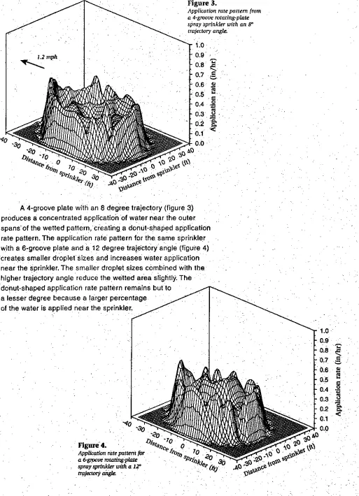
Figure 3.
Application rate pattern from a 4-groove rotating-plate spray sprinkler with an
r
trajectory angle..0
0.9
0
A
vA
aoce"O
- 0.8
- 0.7
= 0.6 1.4
0.5 - g
- 0.4.2
-0.3 .
3 -
=
-- . 0.1
0.0
t)
0.
$101-%/1
A 4-groove plate with an 8 degree trajectory (figure 3)
produces a concentrated
applicatioh
of water near the outer.
spans-of the wetted pattern, creating a donut-shaped application
rate pattern. The application rate pattern for the same sprinkler
with a 6-groove plate and a 12 degree trajectory angle (figure 4)
creates smaller droplet sizes and increases water application
near the sprinkler. The smaller droplet sizes combined with the
higher trajectory angle reduce the wetted area slightly. The
donut-shaped application rate pattern remains but to
a lesser degree because a larger percentage
of the water is applied near the sprinkler.
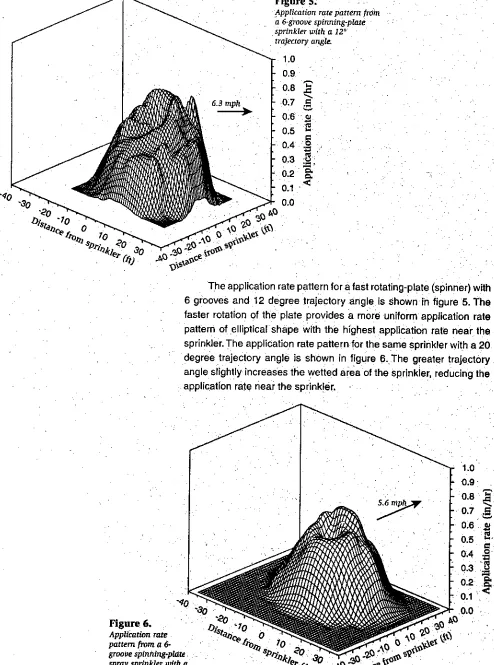
Figure' 4.
Application rate pattern frOin
a 6-groove spinning-plate sprinkler with a 12° trajectory angle
1.0 0.9 - 0.8 - 0.7 - 0.6 - 0.5 - 0.4 - 0.3 0.2 - 0.1 0.0 30 AO o fr-el
sQ
Figure 6.
Application rate pattern from a 6-groove spinning plate spray sprinkler with a 20° trajectory angle.
Figure 5.
The application rate pattern for a fast rotating-plate (spinner) with 6 grooves and 12 degree trajectory angle is Shown in figure 5. The faster rotation of the plate provides a mare uniform application rate pattern of elliptical shape with the highest application rate near the sprinkler. The application rate pattern for the same sprinkler with a 20 degree trajectory angle is shown in figure fi. The greater trajectory angle slightly increases the wetted area of the sprinkler, reducing the application rate near the sprinkler.
1.0 0.9 0.8 .14 0.7 0.6 t
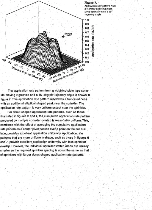
Figure 7.
Application rate pattern from a 9-groove wobbling-plate spray sprinkler with a 15°
trajectory angle.
'40 "30
O
1.0
0.9
- 0.8 -0.7 -. 0.6 0.5 - 0.4 -.0.3 - 0.2 0.1 0.0
s
o
o\e
s
- ".v.
e di
iv s0.11'‘‘
9
4‘5‘ c
The application rate pattern from a Wobbling=plate type sprin-kler having 9 grooves and a 15-degree trajectory angle is shown in figure 7. This application rate pattern resembles a truncated cone with an additional elliptical shaped peak near the sprinkler. The application rate pattern is very uniform except near the sprinkler.
For donut-shaped application rate patterns, such as those illustrated in figures 3 and 4, the cumulative application rate pattern produced by multiple sprinkler overlap is reasonably Uniform. This, combined with the effect of averaging the cumulative applicatiOn rate pattern as a center pivot passes over ,a point on tlie soil
Sprinkler height
Sprinkler height influences the siie of the sprinkler wetted area and wind drift losses. Increasing sprinkler height increases sprinkler wetted area slightly with no significant effect over the practical heights of 6 to 10 feet. Sprinkler heights greater than 6 feet on short crops (height less than 3 feet) do not significantly increase applica-tion uniformity. However, sprinkler heights less than 6 feet signifi-cantly decrease application uniformity, particularly for , sprinklers•• . . having deflection plates with low trajectory angles. With taller crops, the optimal sprinkler height is the maximum canopy height
Sprinkler heights greater than 6 feet significantly increase spray losses due to wind drift and evaporation, Spray losses aver-age about 3 and 5 percent for sprinkler heights of 3 and 6 feet, respectively. Spray losses increase to 10 percent for sprinklers (spray and impacts) mounted, on the top of the center pivot at heights of 12 to 15 feet. Spray losses can double as wind speed increases from 0 to 5 miles per hour to 5 to 10 miles per hour. For short crops; sprinkler heights near 6 feet Provide good application uniformity while maintaining reasonable spray losses.
Wind speed
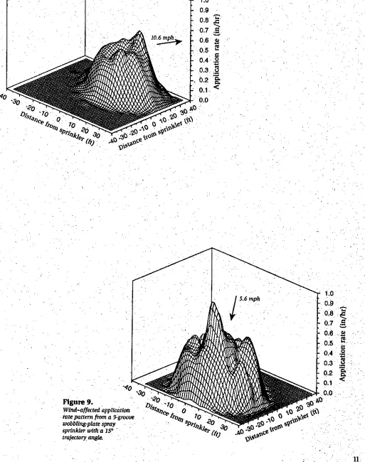
Wind distorts the application rate pattern frorri Spray sprinklers and affects application uniformity. The effects of wind on the applica-tion rate patterns for a Spinner and a VVobbler type spray sprinkler
• .
Wind-affected application rate pattern from a 6-gn?ove spinning-plate spray sprinkler with a 2O° trajectory angle.
1.0
0.9
0.8
0.7
0.6
0.5
go
0.40.3 .1 0.2
ft.
0.1
0.0
AQ
aJ)ce fr o
2
,
s
Pri.oj„ '`u.
e2-1-49 vge
V
iv5t2'
N3
0Figure 9. RO
Wind-affected application DA,-icto rate pattern from a 9-groove
wobbling-plate spray sprinkler with a 15° trajectory angie.
Sprinkler Droplet Kinetic Energy
Many
soils; particblarly those containing significant
silt.frac-tions, are susCeptible to soilsurfaCe sealing , from sprinkler drOplet
impact. The ferce of the droplets hitting the ground breaks doWn :the
surface soil structure, forming a thin compacted layer that greatly
-
infiltration
.
reduces
rate. The application rate and the kinetic energy
of Sprinkler
droplets at
imp
act are the major factors affecting
soil-surface seal forMation. The infiltration rate reduction is a function
of theparticular soil and the energy flux density Energy flux density ,
combines the effects of sprinkler droplet kinetic energy and
water' applicatiOn rateinto a single
parameterthat is expressed as power
per unit area (feet-pounds per minute per square foot or watts per
square meter). It ccirrelates very well with
infiltratiOn rate:•
The relationship
be-tween energy flux density
and depth of infiltration prior
140
to runoff is illUstrated in figure
10 for two different soils
under dry, bare cónditions.
The silt loam soil is very
.
susceptible to soil-surface
sealing. The infiltration depth
.
prior to pOnding decreases
very rapidly with a minimal
increase in energy
flux-densitysoil.
The loaM
is
lesssusceptible to soil-surface
sealing, but the depth of.
infiltration prior to runoff still
I I ' I I I
7
,
0.5 1.0 1.5 2.0 2.5 3.0 3.5
Energy flux density (ft-lb/minift 2)
decreases significantly as •
_energy flux density increases.
' The effect of sprinkler
droplet impact on the infiltra-
,
tion rate of a particular soil must be measured to deVelop a
quantita-tive relationship . similar to that of figure 10: This is difficult bedause
the results depend on Soil surface conditions, aollstructure, and soil
water content. However the general trend shoWn in figure 1'0 is
applicable to any soil and useful in the selection of sprinklers fora •
0.0
Figure 10,
bifatration rate reduction by energy density flux of wrinker droplets for two
soda. Adapted from Thompson and Alma (1985) and :',:telohammed and Kohl (1987).
Center piVot irrigation System.
Stridies of runoff under center pivot .irrigation systems indicate•
that soil-surface sealing continues to develop-With each additional ; •
. • .
irrigation. The only way to recover frornsoil=surface seal formation is
to
physieallydestroy it with a tillage .operation.The , best approach
for limiting
soil-surface seal-
formation to prOtect the soil surface
throUgh
residue managementand-to exclude water application from
bare soil Conditions. • • •
When water applications must be made-on bare soils, the
energy flux density should be reduced to delay formation of the soil-
.
surface seal. This can be accomplished by either using sprinklers
with reduced droplet kinetic energy, reducing application rate, or
both. Reducing th
e application rate is easiest and can, be &me by
.renozzling the, center pivot system to reduce flow rate. The applica-
.
lion rate under a center pivot is independent of system speed, so
adjusting the system speed does not affect formation of a
soil-surface seal.
The kinetic energy of a sprinkler droplet depends on droplet
size (mass) and velocity at impact with the soil surface. Droplet
velocity is also a function of drop size. Drop size distribution is
determined by sprinkler nozzle size, pressUre i and deflection
plate configuration.
Figure 11 shows the kinetic energy per unit volume , of water
applied (foot-pounds per cubic
foot or joulesper kilogram) versus
the dimensionless ratio (ft/ft, m/m) of nozzle size to pressure head
for several types of sprinklers. Droplet kinetic energy is highest for
sprinklers producing the largest drop sizes, such as standard
impact sprinklers and rotator type sprinklerS having deflection
plates with few grooves'.
Droplet kinetic energy is the
lowest for sprinklers
produc-ing small drop sizes such as
500-those using fixed sprays with
flat or serrated plates. There
is little difference in droplet ,
kinetic energy between the
various spray sprinklers,
except for the 4-groove
rotating-plate sprinkler. Overall,
droplet kinetic energy
'varies
only by a factor of, three across
all sprinkler types.
Despite this limited range
in droplet kinetic energy, a
study of sugar beet emergence
comparing sprinklers with 105
ft-lb/ft
3and 315 ft-lb/ft
3of drop- let kinetic energy found a 13
percent increase in ,sugar beet emergence under the sprinkler with
two thirds less droplet kinetic energy (Lehrsch et al.)
•
Sprinkler selection does influence soil-surface seal formation.
•
This not only affects infiltration rate, but has other agronomic
implications such as soil erosion, water application efficiency, and
nutrient distribution in the soil profile..
•
400-g • 30p
-ZQ-
200-
100-0
0.0
0.2
25
9
2. Small mule 3. Square nozzle impact
r
1. La ge nozzle impact , impact pact 4. Rotator, 4-groove plate 5. LDN
6. Rotator, 6-grOove plate 7. Spinner, 6-groove plate 8. Wobbler
9. Fixed-plate, serrated 10. Fixed-plate, smooth
I 0
1.2
1.4
Figure
Sprinkler•dmplet kinetic • energy for varicnis sprinkler
types as a function of the dimensionless ratiovf. sprinkler nozzle diameter to sprinkler pressure head. Adapted from Kincaid (1996)..
I I i
0.4 0.6 0.8 1.0 DIH x 1000
44%,011* 1
0
derii"011411a4
41
4\'`.ii‘v,,,,,,x,xoto
blio;
;;;\
\
\
\
\?
irotol
,
vo!
‘
:
0
0
n
1\"1°°1\101\‘‘Ivio\'‘\‘`'
frilli‘\"\11\'
'
'4"1101\AII\
°
Iiiiii•"""1411141
e
iliii"1\00
0000
\\O
0%0000 ill
lb 14 1,, A970
--seliv 02)
2
0
Figtire 12.
Composite application rate pattern under a center pivot ' from 6-groove rotating-plate sprinklers on drop tubes with 10-foot sprinkler spacing and 10 gallons-per-minute flow rate.
Optimal Sprinkler Package Selection
and Installation
.
-Sprinkler selection and installation have a significant effect on' the performance of a center pivot irrigation system. Both application rate relative to infiltration rate and the susceptibility of the soil to surface sealing need to be considered in the system design; The application rate of low-pressure spray sprinklers can be reduced hy using offset booms on alternate sides of the center pivOt lateral. On soils with extremely low infiltration rates or with a high susceptibility
to soil-surface sealing, offset btioms on both sides of the center piVOt lateral can be used at each sprinkler outlet to further reduce application rate. The effectiveness of offSet booms for reducing application rate is shown in figures 12, 13, and 14.
The composite application rate for 6-groove
rotating-plate
sprinklers on drop tubes is shown in figure 12..
Figure 13 shows the composite application rate Under the same sprinkler conditions with offset bOoms on alternate Sides of the center pivot lateral. The average application rate is reduced abobt 39 percent by offset boorns.
The composite application rate with two offset booms at each sprinkler location and each sprinkler nozzle providing one-half the flOw rate is shown in figure 14. The application rate is redUced 5
percent compared to the single offset bOom:The major advantage of the double offset boom is that it uses smaller nozzles, which reduces the kinetic energy of the droplets. _ •
Figure 13.
Composite application rate pattern under a center pivot from rotating-plate sprinklers on offset booms having a 15-foot horizontal projection on alternate sides of the center pivot lateral with 10-foot sprinkler spacing and 10 gallons-per-minute flow rate.
•4.
• . . . St4
. 11ce 4.041 177tei
Figure 14.
Composite application rate ' -pattern under a center pivot
"
'40
from rotating-type sprinklers: ^
on an offset boom having a •
15-foot horizontal projection on both sides of the center pivot lateral with i0-foot ' sprinkler spacinganti,10_ tallon-pevhour flou? rate,
- - ,
‘oe;,". :it.::!•!..
:
uvolivi\ it•\4
10:4-111;
4:11.-‘..AV4---
S
la j‘ A0
1111‘"10
0 i \\IL1;41, llk,t 1. .il i
sk
i\
►
‘;‘\‘‘Al
a 101\0000 0 ‘161 % 001141b
ti
010.010
9010,1\1\\\I‘te 111110\i ikA
iSellitl\‘1,‘\11:6
‘11101\10,0\
011#001p, €10
V‘\‘‘\\;;;;;.;:1:::1:\::::::7
sox .k,o
Fixed-plate 2.13 - 4.36
serrated 10 1.62_ 3.51
1.32 2.&7
20, 1.15 2.75
98 98 98 98'. •
0 '1.54 2.47' .
.101.17 227 76 92 •
15-7 . 104 . 2.12
•
67.20 6.94 1.65.
61
67:: 1.42 2.41 1.11 2.27
1.co
1,940.90 1.41
'97
..
•97• .
Application rates and application rate reduction provided by offset &Sams of various
lengths with a 10-foot sprinkler spacing and flow rate of 10 gallons per minute.
Table 1'.
Application rate •
Offset • Application rate . reduction Application „-. distance Average High 10% Average High 10% uniformity.
(ft) (lnfhr) (%) CM • X*
Sprinkler
typ
e-
, Table 1 lists the average and highest 10 percent application
rates for various types of spray sprinklers on offset booms installed
on alternate sides of
acenter pivot lateral. The same:information for
. •
two offset booms is listed in table 2. The
exactapplication rates will
change with sprinkler flow rate,
butthe relative reductions will
remain nearly the
same.Offset boonis are relatively inexpensive
and very effective in reducing the application rate..
Since
the
applfdation rate under low-pressure spray sprinklers
• .
can
be minimized by using offset
• booms, •sprinkler seleation should
• be based on drop size distribution.
Smalldrop sizes have the least
• • •
droplet kinetic energy but are the
most•
susceptibleto wind,drift
losses. Large drop sites' have the highest droplet kinetic energYbut
are the least susceptible to wind drift losies. Sprinklers that provide
a compromise between
these
twoextremes are best. Most
moving-plate sprinklera have medium' drop sizes andmaximum
wettedarea. ,
Becaus .they
.
all have aboiii the sautedroplet kinetiOanergy, the
final selectiOn of the brand
rests
on personal preference.••
„ • •The significant differenceg in the application rate patterns of
•the various moving-plate sprinklers- inflUance the spaaing of the'
•
sprinkler heads (table 3). Fixed-plate spray' sprinklers with their
smaller wetted area requing closer
spacing than
the moving -plate
Wobbler
low angle 100 • 15 20 Table 2,
Application rates and reduction provided by double offset booms of various lengths with a 10-foot sprinkler spacing and flow rate of 5 gallons per minute.
Application rate
Offset Application rate Reduction Application distance Average High 10% Average High 10% uniformity
(ft) (inibr) (in/hr) (%) (%) (%) Sprinkler
type
0 • 1.90 10 _ 1.35 15 1.19 20 1.05
68 59 51' .
3.37
2.65 71 1.80 62 1.69 55 Fixed-plate serrated Rotator 6-groove 99 • 99 99 99 97 97 96 97 2.58
2.19 75 85
1.80 • 66 70 1.33 •61 52 1.55
1.17 1.02 0$4
Table 3. •
'Recommended' maximum spkinkler
spacings for low pressure spray sprinklers
at a 6-foot height.
Sprinkler
type 10Pressure (PO15 20 30 Fixed-plate 6 8 8- 10 ' Rotator 4-groove 8 10 12 14 Rotator 6-groove 8 10 12 14 Spiriner,6-groove 8 10 12 14 •
Wobbler low angle- 12 14 14 16
Wobble high angle 14 16 16 18
Pressure also has a significant effect on the required spacing. Higher pressure alloWs wider spacing because of the resulting smoother application rate pattern and slight increase in the wetted area. With most spray sprinklers, low presSure produces a donut-shaped application rate pattern. As a result, closer spacing is needed in order to maintain application uniformity. Due to the high flow rates required on the outer portion of center PiVots,large spacings require large nozzle sizes, which may result in excessively large drops, particiilarly at low pressures.
Increased wind drift lose 2 More uniform application rate ;
pattern allowing larger sprinkler. spicing
More than 15 degrees
•
•
Donut application rate• pattern. requiring closer sprinkler spading to maintain high application uniforinity Deflection plate configuration
Fixed-plate, smooth
Fixed-plate, serrated
Moving-plate, 4-groove
Moving-plate, 6-groove 9-groove
Trajectory. angle Less than.15 degrees
wind drift loss, larger. sprinkler
Spacing
Minimum droplet kinetic energy . High'application rite, high wind drift loss, dose sprinkler spicing required for high application ' uniformity
Low droplet kinetic energy High application rate, :high wind drift loss; clOse sprinkler spacing required for high applidition
uniformity. :
Lowest average application rate,
low wind drift loss, larger sprinkler spacing allowably
LOW average application rate, low
Highest drOplet kinetit energy - ,
Moderate droplet kinetic ene -. •
Reduced wind drift loss•
. . , • •
• • 1 •
-Mounting configuration
Overhead
•..
Low cost, higher uniformity with High wind drift lots larger sprinkler spicing
Drops Reduced wind drift loss
.
. • , .
Offsets Reduced application rate Table 4.
Advanta.ges and disadvantages of spray sprinkler deflection plate features and sprirdder mounting.
Feature Advantages Disadvantages
IriCreased dost, slightly increased •1 applidation rate, spacing more " critical for high application
uniformity - ' •
. .
Summary
• -
Center pivot sprinkler packages have changed significantly
i i
since they were first ntroduced. The original high impact
sprinklers have been . largely replaced by low-pressure spray
Sprin-klers. The current moving-plate spray sprinklers, the - result of years
of development by the sprinkler industry, minimize operating
pres-sure
while
increasingapplication uniforMity.When
,properly selected
.
and installed, these sprinklers provide an efficient center pivot
irrigation system.
- •
In general, there is very little difference in application uniformity
and irrigation efficiency between the common low-pressure
moving-plate spraY sprinklers available today. The primary advantages and
-disadvantages of the various low-pressure spray sprinkler features are
listed in table
4.Offset booms are usually required on the outer spans
of a center pivot to reduce application rates to acceptable levels to
minimize runoff potential, especially on silt loam soils.
Soils susceptible to soil-surface sealing can be protected
by
reducing apPlicatiori rates and droplet kinetic
energy
via the use of
two
offset boems at each sprinkler outlet;temporarily renozzling the
sprinkler package to reduce the system flow rate, and managing
residue through' conservation tillage practices. Even with the use
of;
offsetbooms, application rates from
low
pressUre spray sprinklers
exceed the infiltration
rate
.
of most soils. Basin or reservoir tillage
can
increase
surface storage and significantly reduce actual runoff.
Low pressure spray sprinklers should be installed at a height
of about 6 feet for low growing crops. This height maintains good
application uniformity, limits wind drift; and reducesdroplet
evapora-tion losses to acceptable levels. LEPA paCkages should only
beused on near level topography. The increase in application efficiency: ,
of LEPA systeMs from reduced
educed evaporative and wind drift losSes is
easily overcome by increased runbff on silt loam soils. The
in=
creased cost of LEPA sprinkler packages relative to low pressure
sprinkler packages and the additional effort
neededto plant crop
rows to follow the circular travel of the center pivot
system are
not
•• • • •
.
. . . • ..' •References
Kincaid, D.C. 1996.
Spray drop kinetic energy froM irrigation sprinklers.Trans, ASAE 39(3):847-853;
Kincaid, D.C. 1994.
Comparison of modified LEPA and low eletiation spray system for center pivot irrigation.ASAE Paper No 94-2099. St. Joseph, MI.
Kincaid, D.C., M. Nabil, and J.R. Busch. 1986.
Spray losseS and uniformity with low presSure center pivots.ASAE Paper No 86-2091.
St. Joseph, MI._-Lehrsch, G.A.,
D.C.Kincaid, and
R.D.Lentz. 1996.
PAM spray effects im sugarbeet emergence. ManagingIrrigation Induced Erosion and Infiltration
.Polyacrylamide Conference Proceedings, University of
Idaho,
Moscow, lap. 115-118.
Mohammed, D. and R.A. Kohl. 1987.
Infiltration response to kinetic energy.Trans. ASAE 30(1):108-111.
Thompson, A.L. and L.G. James. 1985.
Water droplet impact and its effect On infiltration.Trans ASAE
28(5)1506-1520.
AuthorS:
•Bradley A. King is an irrigation research engineer in the Biological and Agricultural Engineering
Department at the University of Idaho
.Aberdeen Research and Extension Center:
-
.Dennis C.
Kincaid is an agricultural engineer for the USDA Agricultural Research Service at
theNorthwest Irrigation and
SoilsResearch Laboratory in Kimberly Idaho.
- •
Copyright 0 1997 University of Idaho College of Agriculture
•.• • .. • .
All rights reserved. NQ part of this publication may be reproduced or,:transmitted for commercial purposes in any form or by
any means, elecironic, mechanical, PhotocoPying, recording, or otherwise . without the prior written consent of the publisher. Copies of this publicatiOn can be obtain by sending $5.00 plus $2 00 postage and handling (and 5% Idaho sales
tarif
: applicable) to Agricultural Publications, University of hiaho, Moscow, ID 83844-2240; TEL & FAX 208 885-7982; ckingOuidaho.edu ; v+;ebsite httP://info.ag.uidaho.edu . A copy of the Resources of Idaho catalog of publications And -videos can be obtained free from the same office. ,- •
Issued in furtherance of coOperative Extension work:inagriculture and home econdmics, Aats Of May 8_and June 30, 1914, in cooperátion with 1.73. pepaitment of Agriculture, LeRoy ti. tuft ) birector of Cooperative Extension System,
University of Idaho, MOscow, IdahO, 83844. The University of Idaho provides equal opportunity in education arid employ ment on the basis of rabe, -color, religion, national origin, gender, age, disability, or Status as a Vietnam-era veteran,
a
required by state and federal, laws.
600; 12-97