Abstract—The effective linear attenuation coefficients and build-up factors for single shield of Al, Fe,Pb, and for multi-layer shield of Al-Pb, Al-Fe, Fe-Pb, Al-Fe-Pb as a function of shield thickness, atomic number, and order of the materials composing the shield are investigated for two photon energies of 0.662 MeV and 1.25 MeV. Two derived practical formulas to calculate the effective attenuation coefficient and build-up factor for multilayer shields are used. It is noticed that changing the order of the materials among the shield has no significant effect on the experimental result. Measurement agrees well with the trend of the suggested formulas for calculating the effective attenuation coefficient and the buildup factor. The linear attenuation coefficient is observed to have a strange dependency with the atomic number and photon energy. For single layer shield, the attenuation coefficient increases with decreasing atomic number at low photon energy and increasing with increasing atomic number at high photon energy.
Index Terms—Attenuation coefficient, build-up factors, multilayer shields, radiation dose.
I. INTRODUCTION
The use of gamma rays in medicine, surgery, industry, research and agriculture, made human subject to dangerous diseases. The lack of knowledge in radiation protection principles among which is the use of proper shielding materials increases this risk. In radiation protection, photon build-up factors, and attenuation coefficient, provide convenient information for calculating dose and exposure response after various shielding configurations. Since gamma
______________________________________________________________ ARO-The Scientific Journal of Koya University
Volume III, No 1(2015), Article ID: ARO.10057, 05 pages DOI: 10.14500/aro.10057
Received 22 October 2014; Accepted 15 March 2015 Regular research paper: Published 10 May 2015
Corresponding author’s e-mail: [email protected] Copyright © 2015 Maan S. Al-Arif and Diyaree O. Kakil. This is an open access article distributed under the Creative Commons Attribution License.
rays are very penetrating radiation, selection of shielding materials becomes most important in many cases such as in nuclear accidents, nuclear reactors, research laboratories, in medical institutions, and in high space. People involved in those places may be victims to gamma ray exposure. Moreover, on 2009, NASA has identified the need for developing advanced radiation-shielding materials and structures to protect humans from the hazards of galactic cosmic radiation during lunar missions (NASA, Proposal Number: 09-1X4.01-8309, Sub-topic X4.01, NASA SBIR 2009 Solicitation). NASA proposed to develop lightweight, multi-layered shield with an outer layer of hydrogenous polymeric material. This shield is designed and fabrication of materials tailored to shield against hazardous radiation.
Mathematically methods to solve the problem for multilayer shield may be divided in two groups: the semi-empirical methods based on the use of experimental or theoretical data and method uses low order approximation of the transport equation and Monte Carlo program (Nelson,, Hirayama and Rogers, 1985). However, the relatively accurate solution of the gamma radiation transport equations is realized only for the simple geometrical configurations.
Buildup factor, which is important in calculating radiation shielding and absorbed dose, have been widely studied by various research groups (Shin, and Hirayama, 2001; Alamatsaz, and Shirani, 2002; Saudi, 2013). However, the variation of the buildup factor with penetration distance in multi-layered shield differs from that in homogenous media (Balwinder, et al., 2013). This variation depends on attenuation, buildup factor, and thickness for both penetrated layers.
In this research, experimental measurement for the buildup factor and attenuation coefficient for single and multi-layer shields at Cs-137 and Co-60 gamma energies will be carried out. The experimental result will be used to derive a practical formula for calculating the effective buildup factor and attenuation coefficient for multilayer shields. We believe that in practice the design of multi-layer shield for any purposes need a simple method of calculation with good accuracy.
Calculated-Experimental Model for
Multilayer Shield
Maan S. Al-Arif
1and Diyaree O. Kakil
21
School of Medicine, Koya University
Danielle Mitterrand Boulevard, Koya KOY45, Kurdistan Region of F.R. Iraq
2
Department of Physics, Koya University
II. THE EXPERIMENTAL MODEL
In practice, broad beam geometry must be considered. The quantity of radiation transmitted through the shield, I, is given by;
𝐼 = 𝐵𝐼0𝑒−𝜇𝑥 (1)
Where; I0 is the incident intensity, exp (-μx) is the attenuation factor and B is the buildup factor.
In the present work, three-layer shield geometry will be assumed as in Fig. 1. Photon beam with intensity, I0, is
assumed to be incident perpendicularly on the plane of the shield.
The intensity of the beam entering the second, third layer, and that leaving the third layer of the shield is given by;
𝐼1= 𝐼0 𝐵1𝑒−𝜇1𝑥1 (2)
𝐼2= 𝐼1 𝐵2𝑒−𝜇2𝑥2 (3)
𝐼3= 𝐼2 𝐵3𝑒−𝜇3𝑥3 (4)
Substitute (I1 and I2) from (2) and (3) into (4), and rearrange
the equation, we get;
∴ 𝐼3= 𝐼0 (𝐵1𝐵2𝐵3) 𝑒−(𝜇1𝑥1+𝜇2𝑥2+𝜇3𝑥3) (5)
If we consider the shield as one unit, we can say;
𝐼3= 𝐼0 𝐵𝑒𝑓𝑓 𝑒−𝜇𝑒𝑓𝑓 𝑥𝑡𝑜𝑡 (6)
From (5) and (6), we get;
𝐵𝑒𝑓𝑓 = 𝐵1𝐵2𝐵3 (7)
and
𝜇𝑒𝑓𝑓 =
𝜇1𝑥1+𝜇2𝑥2+𝜇3𝑥3
𝑥𝑇𝑜𝑇 (8)
The present work aims to verify experimentally the validity of (7) and (8) by measuring μ1, μ2, μ3, B1, B2 and B3. The
results obtained will then be used to calculate the effective buildup and attenuation coefficient for different multi-layer shields.
III. MATERIAL AND METHODS
The attenuation coefficient for single and multi-layered shields is carried out by using the narrow beam geometry shown in Fig. 2. The photon beam is directed perpendicular to plane of the shield. Measurements of the attenuation coefficient are carried out for three single elements of Al, Fe, Pb, and for four multi-layer shield combinations of Pb, Al-Fe, Fe-Pb, and Al-Fe-Pb are carried out. The effect of reversing the order of the materials among the shield is also investigated.
The Attenuation coefficients were measured using NaI (TI) scintillation detector connected to a multi-channel analyzer (MCA), having energy resolution of 12.5 % at 662 keV. Plane radioactive sources of Co60 and Cs137 with activities of 5μCi,
1μCi, and effective photon energy of 0.662 MeV, 1.25 MeV are considered for the sources respectively.
Fig. 1. The multi-layer shield geometry.
Fig. 2. The irradiation geometry
A broad beam and narrow beam geometries are used in measuring the buildup factor. The broad beam geometry is achieved by removing the collimator in front of the attenuator in Fig. 2. The build-up factor can be deduced experimentally as the ratio of the transmitted beam intensity from a broad beam geometry, T`, to that transmitted from a narrow beam geometry, T, and is given by;
𝐵 =𝑇`
𝑇 = 𝐵𝑒−𝜇𝑥
𝑒−𝜇𝑥 (9)
Measurements for the buildup factor are carried out for three single elements of Al, Fe, Pb, and for three multi-layer shield combinations of Al-Pb, Al-Fe, Fe-Pb at 0.662 MeV and 1.25 MeV photon energies. The effect of changing the order of the materials among the shield is also investigated in this study.
IV. RESULT AND DISCUSSION
A. The Effective Attenuation Coefficient
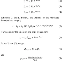
Measurement for the linear attenuation coefficient for single element of Al, Fe, and Pb at 0.662 MeV and 1.25 MeV are carried out using narrow beam geometry and the result are shown in Fig. 3 and Fig. 4.
The experimental result for the linear attenuation coefficients for the three single elements and that calculated by (Hubbel and Berger, 1987; Hubbell and Seltzer, 1996) are
Collimator
Attenuator
Detector
Source
B1 B2 B3
I1 I2
I3
I0
x1 x2 x3
shown in Table I. The calculated values appear to be overestimating the experimental results.
Fig. 3. The attenuation factor for Al, Fe, and Pb as a function shield thickness
at 0.662 MeV
Fig. 4. The attenuation factor for Al, Fe, and Pb as a function shield thickness
at 1.25 MeV
The measured attenuation coefficients for three multi-layer shields of Al-Fe, Al-Pb, and Fe-Pb at 0.662 MeV is shown in Fig. 5.
Fig. 5. The attenuation factor for Al-Fe, Fe-Pb, and Al-Pb shields as a
function of shield thickness at 0.662 MeV.
The measured linear attenuation coefficients for single layer shields are then used to calculate the effective linear attenuation coefficient for the three multi-layer shield at 0.662 MeV using (8). Table II shows the calculated effective attenuation coefficient and the measured values for different multi-layer shield combinations. A good agreement between them is recorded. No significant effect for changing the order of the material of the shields is observed.
TABLEI
THE EXPERIMENTAL AND CALCULATED LINEAR ATTENUATION COEFFICIENT
(CM-1)
0.662 MeV 1.25 MeV
Shield Experimental Calculated Experimental Calculated
Al Fe Pb
0.154 0.437 1.059
0.2003 0.578 1.322
0.0995 0.3046 0.6636
0.1482 0.4793 0.6418
TABLEII
THE EXPERIMENTAL AND CALCULATED LINEAR ATTENUATION COEFFICIENT
(CM-1) AT 0.662MEV
Shield Calculated Experimental % error
Al-Pb Al-Fe Fe-Pb
0.608 0.296 0.749
0.635 0.294 0.737
4.4 0.6 2.9
The validity of (8) for the multi-layer shield of Al-Fe-Pb is also checked at 0.662 MeV and 1.25 MeV photon energies and the result is shown in Fig. 6. It is clear from our result that no significant effect for changing the order of the material of the shield had been seen.
Fig. 6. The attenuation factor for Al-Fe-Pb shield as a function of shield
thickness at 0.662 MeV and 1.25 MeV.
Table III shows the measured and calculated attenuation coefficient for Al-Fe-Pb shield at 0.662 MeV and 1.25 MeV. The experimental result is in a good agreement with that calculated by using (8).
0 0.5 1 1.5 2 2.5 3 3.5
0 0.5 1 1.5 2 2.5 3 3.5
ln
T
Thickness (cm) Pb
Fe
Al
0 1 2 3 4 5 6
0 2 4 6 8 10
ln
T
Thickness (cm) Al Pb
Fe
0 0.5 1 1.5 2 2.5
0 1 2 3 4
ln
T
Thickness (cm)
Al-Pb
Al-Fe Fe-Pb
0 0.2 0.4 0.6 0.8 1 1.2 1.4 1.6 1.8 2
0 1 2 3 4
ln
T
Thickness (cm) 0.662 MeV
TABLEIII
CALCULATED AND EXPERIMENTAL LINEAR ATTENUATION COEFFICIENT IN UNIT OF (CM-1)
0.662 MeV 1.25 MeV
S h ie ld Ex p er im en ta l C al cu la te d % er ro r Ex p er im en ta l C al cu la te d % er ro r
Al-Fe-Pb 0.5395 0.4947 9
0.2971 0.3192 5.9
B. The Build-up factor
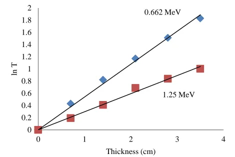
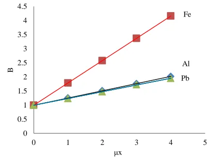
The build-up factors, B, as a function of thickness in units of mean free path (m.f.p) for single elements of Al, Fe, and Pb are measured using a broad and narrow beam geometries at 0.662 MeV and 1.25 MeV, and are shown in Fig. 7 and Fig. 8.
Fig. 7. The build-up factor for single layer shield as a function of shield thickness at 0.662 MeV
Fig. 8. The build-up factor for single layer shield as a function of shield thickness at 1.25 MeV.
We can see from Fig. 7 and Fig. 8 that the build-up factor at 1.25 MeV increases with shield thickness and with the atomic number of the shield material, while at 0.662 MeV, the
build-up factor for Al is lower than that for Fe and become very close to that for Pb. This agrees well with other findings of some researchers (Abdulfattah, 2010; Al-Baiti, 2010; Jasbir, Barjinderpal and Gurdeep, 2012). They noticed that the build-up factor has a strange dependency with the atomic number and photon energy, increasing as atomic number decreasing at low energy and increasing with increasing atomic number at high energy.
The experimental values of build-up factor for single layer shields are then used to calculate the effective build-up factor for multi-layer shields of Al-Pb, Al-Fe, and Fe-Pb, according to (7) for 0.662 MeV and 1.25 MeV. The calculated and measured values are shown in Table IV. No significant effect for changing the order of the material in the shield is observed with the exception of the case for Fe-Pb and Pb-Fe shields where the % error increases to about 8 % at 0.662 MeV and 12 % at 1.25 MeV. The experimental measurements are in a good agreement with calculated values.
TABLEIV
CALCULATED AND EXPERIMENTAL BUILD-UP FACTOR
0.662 MeV 1.25 MeV
S h ie ld Th ic k n ess (c
m) Exp
C al cu la te d % er ro r Ex p C al cu la te d % er ro r
Al – Pb Pb – Al
2 – 2 2 – 2
1.465 1.408
1.508 2.8
6.6 1.734 1.678
1.665 4.1
0.7
Fe – Al Al – Fe
2 – 2 2 – 2
1.489 1.557
1.553 4.1
0.2 1.387 1.455
1.391 0.2
4.2
Pb – Fe Fe – Pb
2 – 2 2 – 2
2.081 1.847
2.013 3.3
8.0 2.037 1.76
2.004 1.6
12.1
V. CONCLUSION
It was shown that (7) is in a good agreement with the experimental results for both radiation qualities investigated in this research. It indicates that the effective attenuation coefficient for multi-layer shield is the sum of the fractional thickness multiplied by the attenuation coefficient of the materials composing the shield. No significant effect for changing the order of the materials of the shield on the measured effective attenuation coefficient is recorded.
It was also shown that (8) is in a good agreement with the experimental results for the radiation qualities investigated. It indicates that the effective build-up factor is the product of the build-up factor of the materials consist the shield. No significant effect for changing the order of the material of the shield on the measured build-up factor is observed. A strange dependency of the linear attenuation coefficient on the atomic number and photon energy is observed. It was observed that the attenuation coefficient for single elements increases with decreasing atomic number at low energy and increasing with increasing atomic number at high energy.
0 0.5 1 1.5 2 2.5 3 3.5 4 4.5
0 1 2 3 4 5
B μx Fe Al Pb 0 0.5 1 1.5 2 2.5 3
0 1 2 3 4 5
B
μx
Pb
Fe
This paper concludes that (7) and (8) are simple, having a good accuracy and can be used to design a multi-layer shield of similar geometry used in this research.
REFERENCES
Al-Baiti, K.O., 2010. Calculation of Dose Gamma Ray Buildup Factor up to
Thickness of 20 mfp using Taylor's Method. Journal of Kufa University-
Physics, (2)2, pp.33-41.
Alamatsaz, M.H. and Shirani, A., 2002. A study of gamma exposure buildup factors in stratified shields for point isotropic sources, including the effectives
of incoherent and coherent scattering. Journal of science, Islamic republic of
Iran, (3)13, pp.271-279.
Abdulfattah, A.A., 2010. Effect of exposure buildup factors on reactor
shielding. Journal of Al-Nahrain University, (1)13, pp.78-83.
Balwinder, S., Vipan, K., Sukhwinder, S., Gurdeep, S.S., 2013. Investigations of mass attenuation coefficient and energy absorption buildup factor of some
low-Z gamma ray shielding materials. International Journal of Latest
Research in Science and Technology,(5)2, pp.73-77.
Hubbel, J.H. and Berger, M.J., 1987. Photon cross sections, attenuation coefficients, and energy absorption coefficients from 10 keV to 100 MeV. National Bureau of Standards report NSRDS-NSB29, pp.3597-3598.
Hubbell, J.H. and Seltzer, S. M., 1996. Tables of X-Ray Mass Attenuation Coefficients and Mass Energy-Absorption Coefficients from 1 keV to 20 MeV
for Elements Z = 1 to 92 and 48 Additional Substances of dosimetric interest.
Radiation and Biomolecular Physics Division, PML, NIST.
Jasbir, S.D., Barjinderpal S. and Gurdeep S.S., 2012. Gamma Ray Photon
Energy Absorption Buildup Factor Study In Some Soils. IOSR Journal of
Applied Physics (IOSRJAP), (6)1, pp.14-21.
Shin, K. and Hirayama, H., 2001. Calculation of gamma-ray buildup factors for two-layered shields made of water, concrete and iron and application of
approximating formula. Radiation Physics and Chemistry, 61(3), pp.583–584.
Nelson, W.R., Hirayama, H. and Rogers, D.W.O, 1985. "The EGS4 code system" SLAC-265, Stanford Linear Accelerator Center, Stanford, California.
Saudi, H. A., 2013. Lead Phosphate Glass containing Boron and Lithium
Oxides as a shielding material for Neutron and Gamma Radiation. Applied