Fuzzy logic based PSS in Coordination with STATCOM Power
Oscillation Damping (POD) controller for Small Signal Stability
Enhancement of Multi-machine Power System
Prabodh khampariya1, N. P. Patidar2, R. P. Singh1, Laxmikant Nagar3 1Sri Satya Sai University of Technology & Medical Sciences, Sehore India
2Maulana Azad National Institute of Technology, Bhopal, India 3University Institute of Technology, RGPV, Bhopal, India
[email protected]; [email protected]; [email protected]; [email protected];
Abstract— this paper presents a coordinated Fuzzy
logic based PSS with STATCOM Power Oscillation Damping (POD) Wide Area Damping Controller (WADC) and simultaneous tuning of FACTS based controller and fuzzy logic based global PSS. The disturbance is symbolized as distributed in the network with consideration of momentarily disturbance to the generator in area 1 for few cycles. The tie-line active power flow from among areas, rotor speed deviation and speed, rotor mechanical angle deviation, positive sequence voltage are studied by seeing the test system with conventional PSS (CPSS), fuzzy logic based controller and coordinated fuzzy logic based PSS with shunt connected FACTS controllers specifically STATCOM with Power Oscillation Damping (POD). The simulation results are carried out for validation of the proposed coordinated controller.
Index Terms— Power system stabilizer (PSS), Wide
Area Damping Controller (WADC)), Small signal Stability, Static Compensator (STATCOM)
I. INTRODUCTION
Power system nowadays is a complex network, sometimes made of thousands of buses and hundreds of generators. available power generation usually does not situated near an uprising of load center. in order to meet the growing power demand, instead of building new transmission lines and expanding substations, utilities have a concern in better utilization of available power system capacities, existing generation and existing power transmission network [2]. on the other hand, power flows in some of the transmission lines are overloaded, which has as an overall effect of deteriorating voltage profiles and decreasing system stability and security. in addition to this, existing traditional transmission facilities, in most cases, are not designed to handle the control requirements of complex and highly interconnected power systems [1]. this situation requires the review of traditional transmission methods and practices, and the creation of new concepts, which would allow the use of existing generation and transmission lines up to their full capabilities without reduction in system stability and security.
The traditional approach to damp out inter-area oscillations is through conventional Power System Stabilizer (CPSS), forming part of the generator excitation system and FACTS controllers, which
employ locally available or measured signal as input [4]. These local signal based controllers lack the global observations.
In this paper, the research on detailed analysis of wide area damping controller considering FACTS based shunt controllers in coordination with fuzzy logic based global power system stabilizer gestated to damp inter-area or low frequency oscillations in large integrated power system. Section II describes the test system taken in the analysis. In section III dynamic equations are linearized about a steady state operating point. Electromechanical oscillations and their frequency range are discussed in section IV. Fuzzy logic based global PSS and shunt connected FACTS controllers for the proposed WADC are discussed in Section V, VI and VII.
In section VIII, the nonlinear simulation on interconnected multi-machine test system has been performed with PSS; fuzzy logic based global PSS and Coordinated Fuzzy with FACTS controllers to evaluate the performance of the system.
II. INTRODUCTION TO TEST SYSTEM
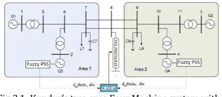
In spite of the high degree of activeness in recent years on wide-area control, there are many aspects remain poorly understood due to the complexity in large power system. Hence, Kundur’s benchmark two areas four machine systems has been carried out to analyze the different types of oscillations that occurs in the integrated power system with proposed robust coordinated fuzzy logic based PSS with FACTS wide area damping controller. In the test system all the generators are equipped with governor, AVR, and IEEE ST1A type static exciter.
Fig 2.1: Kundur’s two area Four Machine system with Coordinated fuzzy and FACTS controllers
case study power system is given in Fig.2.1. After the calculation of most suitable stabilizing signal and control location [6], a fuzzy logic based global PSS is employed supplement to the input of AVR along with FACTS controllers connected in shunt with the tie line connecting both the areas for the effective damping of inter area oscillations.
III. LINEARIZED MODEL
The stability of the operating point of a dynamic system to small disturbances is termed small signal stability. To test for small signal stability the system’s dynamic equations are linearized about a steady state operating point to get a linear set of state equations.
The theory of linear system provides very useful information about the operating behavior and dynamic behavior of the interconnected power system. In fact low frequency oscillations are linear when small disturbance. An interconnected power system network can be represented by the following set of non-linear differential and algebraic equations
Where and are vectors of differential and algebraic equations respectively and is vector of output equations. The notation , and
are the state, algebraic, input, output vectors respectively is the dimension of system, is the no. of inputs, is the no. of outputs.A linear model of the network is used for selection of control signal. After linearizing the system around an operating point the state space model of the system can be represented
Where , and are state, input and
output vector respectively. Where as , are state, input and output matrix
respectively.
In addition to the critical mode identification, modal analysis was also performed for coherent machine identification where the one group of generators forms one area and oscillating with another group of generators. Following each rate of change of state calculation, the perturbed state is returned to its equilibrium value and the intermediate variable values are reset to their initial values. Each step in this process is similar to a single step in a simulation program.
IV. ELECTROMECHANICAL MODES
Interconnected power systems exhibit several kinds of oscillations when subjected to a perturbation. These oscillations are also named as power swings and to maintain the system stability these oscillations must be effectively damped. Oscillations in power systems are separated by the system factors. Some of the major oscillations [2] attributed to system collapse are as follows:
1) Intraplant mode: Generator units at the same power plant oscillate with each other at 2.0 to 3.0 Hz conditional on the generator capacities and connecting impedances [2].
2) Local plant mode: One generator unit swings against the rest of the generators at 1.0 to 2.0 Hz. The influence of the oscillation is confined to the generator and grid connection [2].
3) Inter-area mode oscillations: This occurrence is noticed over a great part of the power system. It includes two coherent groups of generators swinging in contradiction of for each other at 1 Hz or less. The oscillation frequency is roughly 0.3 Hz [2].
4) Control mode oscillations: They are related with generators and badly regulated exciting system, turbine-governors, power controllers. Active and reactive power controllers can interact with each other [2].
5) Torsional mode oscillations: They are related with a turbine shaft in the frequency range of 10-46 Hz. Generally they are created when a multi-stage turbine is integrated to the grid via a series compensated link. [2].
V. OPTIMALSIGNALSELECTIONAND CONTROLSITELOCATION The tie-line active power flow at various lines of the system has been taken for signal selection. The signal selection is carried out by residue approach and geometric measure of controllability/observability approach. Table-II and Table-III shows results obtained from Residue approach and Geometric approach respectively.
Table II: Normalized values of the Residue approach for the 4 machine two area system
Signals Generators
G-1 G-2 G-3 G-4
P6-7 0.5298 0.6849 0.5206 0.6686 P7-8 0.3545 0.4584 0.3484 0.4475 P8-9 0.3224 0.4169 0.3168 0.4070 P9-10 0.7735 1 0.7601 0.9763 Table III: Normalized values of the geometric measure of controllability/observability approach for 4 machine
11 bus system.
Generators Signals
G-1 0.3528 0.7735 0.7655 0.4179
G-2 0.4560 1 0.9897 0.5402
G-3 0.3466 0.7601 0.7522 0.4106 G-4 0.4452 0.9763 0.9662 0.5274
area signals. The basic criteria for selection of the signal are to have good observability and controllability of the signal for the systems inter area mode. So the signal which allows maximum observability and controllability of system’s mode has to be selected as the most effective stabilizing signal for the controllers.
VI. FUZZY LOGIC BASED GLOBAL PSS
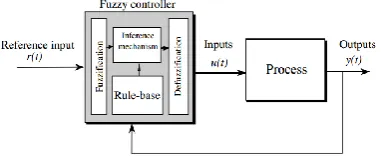
The fuzzy control system block diagram is shown in Figure 5.1. Here, a fuzzy controller embedded in a closed-loop control system. The plant outputs are denoted by y (t), its inputs are denoted by u (t), and the reference input to the fuzzy controller is denoted by r (t).
Figure 6.1: Block Diagram of Fuzzy Control System The fuzzy controller has four main components:
a) The fuzzification interface simply modifies the inputs and converts controller inputs into information that can be easily utilized by the inference mechanism to apply rules so that they can be interpreted and compared to the rules in the rule-base.
b) The rule-base is a set of If-Then rules that contains a fuzzy logic quantification of the expert’s linguistic description. Rule-base holds the knowledge in the form of a set of rules to achieve good control over the system.
c) An inference engine or inference mechanism emulates the expert’s decision making and evaluates which control rules are relevant at the current time and then decides what the input to the plant should be.
d) The defuzzification interface converts the conclusions reached by the inference mechanism into the actual inputs to the plant for the process.
Figure 6.2: General Structure of the Proposed Control Scheme
The proposed control scheme employs additional stabilizing control signal applied to the input of exciter through AVR, as a result an enhanced stabilizing signal through excitation systems is fed to selected individual
generators involved in the controlling areas. The rule base for the fuzzy logic controller is designed. In this research, the two inputs i.e. speed deviation and tie line active power deviation [19], result in 49 rules for each machine. The rule base employing the rules for two inputs i.e. speed deviation and tie line active power deviation is given in Table 5.1
Table 5.1 Rule base for the Fuzzy logic based PSS Speed
Deviation LN MN SN Tie Line Power ZE SP MP LP LN LP LP LP MP MP SP ZE
MN LP MP MP MP SP ZE SN
SN LP MP SP SP ZE SN MN
ZE MP MP SP ZE SN MN MN
SP MP SP ZE SN SN MN LN
MP SP ZE SN MN MN MN LN
LP ZE SN MN MN LN LN LN
The fuzzy logic based global PSS implemented for each area in two area four machine system is employing a global signal from power system as input to the stabilizer. The first input to the fuzzy logic controller incorporated in this research is speed deviation of respective generator and the second input is extracted from the active power transfer across the tie-line connecting both coherent areas [17]. The output of fuzzy logic based global PSS provides the global stabilizing voltage signal for generator through its excitation system.
VII. INTRODUCTION TO FACTS
The process to permit, site, and construct new transmission lines has become extremely difficult, expensive, time-consuming, and controversial. FACTS technologies allow for improved transmission system operation with minimal infrastructure investment, environmental impact, and implementation time compared to the construction of new transmission lines. FACTS controllers control the interrelated parameters that govern the operation of transmission system like series impedance, shunt impendence, current, voltage and phase angle. So FACTS controllers can be utilized to control power flow and enhance system stability [8]. A better utilization of the existing transmission systems by increasing their capacities close to the thermal ratings and enhancing controllability by installing FACTS controllers becomes imperative in today’s competitive power market. There are two main aspects that should be considered in using FACTS controllers: The first aspect is the flexible power system operation according to the power flow control capability of FACTS controllers. The other aspect is the improvement of stability of power systems.
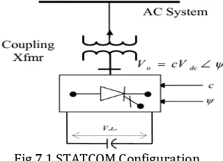
A.Static Compensator (STATCOM)
The STATCOM is made up of a coupling transformer, a VSC, and a dc energy storage device. The energy storage device is a relatively small dc capacitor, and hence the STATCOM is capable of only reactive power exchange with the transmission system [10]. If a dc storage battery or other dc voltage source were used to replace the dc capacitor, the controller can exchange real and reactive power with the transmission system, extending its region of operation from two to four quadrants.
Fig 7.1 STATCOM Configuration.
The STATCOM’s output voltage magnitude and phase angle can be varied. By changing the phase angle ψ of the operation of the converter switches relative to the phase of the ac system bus voltage, the voltage across the dc capacitor can be controlled [11], thus controlling the magnitude of the fundamental component of the converter ac output voltage, as Vo= c Vdc.
VIII. STATCOM with POD based WADC There are various techniques proposed for WADC synthesis including time delay effects such as multi-agent , predictor-based , and mixed
controllers for time-delayed systems, where referred to as Henkel Norm [6-8]. Communication delay in remote signal transmission can be subdivided into two parts; time taken from measurement site of PMU to the phasor data concentrator and then to the control site or the location of the local PSS where the compensating output signal of the WADC is added in supplement to the output of the local PSS and exciter voltage reference
The purpose of FACTS wide area damping control is to shift all the system eigenvalues into the left hand side of the S-plane, so that the needed minimum damping ratio can be satisfied and the system damping can be increased into the acceptable level. As the power oscillation is a prolonged dynamic event, it is essential to vary the applied shunt compensation, and thereby the (midpoint) voltage of the transmission line, to antagonize the accelerating and decelerating swings of the disturbed machine(s). That is, when the rotationally oscillating generator accelerates and angle increases (d /dt >0), the electric power transmitted must be increased to compensate for the excess mechanical input power. Conversely, when the generator decelerates and angle decreases (d /dt <0), the electric power must be decreased to balance
the insufficient mechanical input power [9]. (The mechanical input power is assumed to be essentially constant in the time frame of an oscillation cycle.)
The requirements of Var output control, and the process of power oscillation damping, is illustrated by the waveforms in Figure 8.1. Waveforms in Figure 8.1 (a) shows the undamped and damped oscillations of angle around the steady-state value 0. Waveforms in Figure 8.1 (b) shows the undamped and damped oscillations of the Electric power P around the steady-state value Po. (The momentary drop in power shown at the beginning of the waveform represents an assumed disturbance that initiated the oscillation) Waveform 8.1 (c) shows the reactive power output on of the shunt-connected Var compensator. The capacitive (positive) output of the compensator increases the mid-point voltage and hence the transmitted power when d /dt >0, and it decreases those when d /dt < 0
Fig. 8.1: Waveforms illustrating power oscillation damping by reactive shunt compensation: a) generator
angle, (b) transmitted power, and (c) Var output of the shunt compensator.
IX. CLOSED LOOP VERIFICATION AND NON
-LINEAR TIME DOMAIN SIMULATION
The performance of the proposed power system stabilizer is first verified by small signal analysis. A small disturbance (1+0.05) to the voltage reference input of exciter of generator 1 is applied. Time response analysis of the proposed close loop control system is performed for the verification of the expected outcomes. The loads in the system are assumed to be constant impedance type. To damp out local modes of oscillations and inter-area modes of oscillations the tie line is left connected with shunt type FACTS based Wide Area Damping Controller.
Fig. 9.1 Response of voltage with conventional PSS for Two Area Four Machine System
Fig 9.2: Response of tie-line active power flow deviation with STATCOM
Fig. 9.3: The response of change in rotor angle of generator 1 w.r.t. generator 4
Fig 9.4: The response of rotor speed deviation of Generator1
The responses of the tie-line active power flow deviation, change in rotor angle of generator 1 with respect to the variation of the rotor angle of generator 4 and rotor speed deviation of Generator1 with Conventional Power System stabilizer, fuzzy logic based PSS and coordinated fuzzy logic based PSS with STATCOM Power Oscillation Damping (POD) controller 9are shown in figure 9.1, 9.2 and 8.3 respectively. The
response of terminal voltage of bus no. 9 where the coordinated fuzzy with STATCOM Power Oscillation Damping (POD) controller has been used as the wide area damping controller is shown in fig. 8.4
Fig. 9.5: The response of terminal voltage of bus no. 9
The performance responses of coordinated fuzzy logic based PSS with STATCOM based wide area damping controllers has been studied and it can be concluded from the responses that the coordinated STATCOM based WADC provides a better stability response as compared to conventional controller.
X. CONCLUSION
In this paper, the present work contributes in the area of power system stability and its improvement using coordinated design of fuzzy logic based damping controllers along with shunt connected FACTS devices. Design the FACTS based controllers and simultaneous tuning of FACTS based controller and fuzzy logic based global PSS has been undertook. A lead-lag based POD has been designed in the case of power system using STATCOM based Wide Area Damping Controller. In order to test the performance of the designed STATCOM based wide-area controller a small signal stability assessment has been performed and the results have been validated.
REFERENCES
[1].P. Kundur, ‘Power System Stability and Control’,
TATA McGraw-HILL Edition, 1994.
[2].B.C. Pal, ‘Robust Control in Power Systems’,
Springer, 2005.
[3].I. Kamwa; M. Dobrescu; A. Heniche,; C. Cyr; and Ph.
Cadieux; –‘A fundamental Study of Wide-Area Damping controllers with Application to Fuzzy-Logic Based PSS Design for Dynamic shunt Compensators’ – 17th Power Systems Computation Conference, Sweden, August 22-26 2011.
[4].A.M. Almutairi, ‘Optimal Input and Output Signal
Selection for Wide-area Controllers’, IEEE Bucharest Power Tech Conference, Bucharest, Romania, pp. 1-6, 2009.
[5].K. Anaparthi, B. Chaudhuri, N. Thornhill, and B. Pal,
“Coherency identification in power systems through principal component analysis,” IEEE Trans. Power Syst., vol. 20, no. 3, pp. 1658–1660, Aug. 2005.
[6].M. R Shakarami; M. Khoram Khoy, “Selection of an
IEEE Iranian Conference on Electrical Engineering (ICEE), pp: 580 – 584, 2014
[7].Simon P. Teeuwsen, “STATCOM with optimized POD
controller for efficient inter-area oscillation damping”, IEEE Power & Energy Society General Meeting, pp: 1 – 5, 2013
[8].M. M. Farsangi; Yong Hua Song; K. Y. Lee, “On
selection of supplementary input signals for STATCOM to damp inter-area oscillations in power systems”, IEEE Power Engineering Society General Meeting, pp: 3068 - 3073 Vol. 3, 2005
[9].Aman Ganesh; Ratna Dahiya; G. K. Singh,
“Wide area adaptive neuro
fuzzy STATCOM controller for dynamic stability enhancement”, IEEE National Power Systems Conference (NPSC), pp: 1-6, 2016
[10].R. Visakhan; R. Rahul; K. R. Hridya; Asha Anu
Kurian, “Analysis of power oscillation damping capability of STATCOM-POD and optimal placement of PMUs in IEEE-14 bus system”, IEEE International Conference on Power, Instrumentation, Control and Computing (PICC), pp:1-7, 2015
[11].R. Visakhan; R. Rahul; Asha Anu Kurian,
“Comparative study of PSS and FACTS-POD for power system performance enhancement” IEEE International Conference on Power, Instrumentation, Control and Computing (PICC), pp:1-6, 2015
[12].Simon P. Teeuwsen, "POD utilization methods for
STATCOMs”, IEEE PES General Meeting Conference & Exposition, pp:1-5, 2014
[13].N. P. Patidar, M. L. Kolhe, N. P. Tripathy, B. Sahu, A.
Sharma, L. K. Nagar and A. N. Azmi, “Optimized Design of Wide-Area PSS for Damping of Inter-Area Oscillations”, 2015 IEEE 11th International Conference on Power Electronics and Drive Systems (IEEE PEDS 2015), pp 1-5, 2015.
[14].A. Sharma, L K Nagar, B Sahu, N. P. Tripathy, N. P.
Patidar, “Time Latency Compensation for Wide Area Damping Controller”, 6th IEEE Power India International Conference, DTU, Delhi, December 2014.
[15].N. P. Patidar, J. Earnest, L.K. Nagar, A. Sharma,
“Design of Fuzzy Logic based Global Power System Stabilizer for Dynamic Stability Enhancement in Multi-machine Power System”, World Academy of Science, Engineering and Technology, International Science Index, Electrical and Computer Engineering, vol. 2(8), pp. no. 323, 2014.
[16].P. Kundur, J. Paserba, “Definition and Classification
of Power System Stability,” IEEE Transactions on Power Systems, vol. 19, no.2, pp. 1387-1401, May 2004.
[17].Gonzalez Miguel Ramirez; Malik O. P.; - ‘Simplified
Fuzzy Logic Controller and its Application as a Power System Stabilizer’, Pub: IEEE, 2009.
[18].Hariri A.; Malik O.P; - ‘A Fuzzy Logic Based Power
System Stabilizer with Learning Ability’, IEEE Transactions on Energy Conversion, Pub: IEEE, Vol. 11, No. 4, December 1996, pp. 721-727.
[19].Hoang P.; Tomsovic K.; - ‘Design and analysis of an
adaptive fuzzy Power System Stabilizer’, - IEEE Transactions on Energy Conversion, Pub: IEEE, Vol. 11. No. 2, June 1996, pp. 455-461.
[20].Gharaveisi A. A.; Rafiei S. M. R.; Barakati S.M.; - ‘an
Optimal Takagi-Sugeno Fuzzy PSS for Multi- Machine Power System’, Pub: IEEE, 2008.
[21].Gowrishankar, K.; Masud Khan, M.D.; - ‘MATLAB
Simulink Model of Fuzzy Logic Controller with PSS and its Performance Analysis’ – IEEE International Conference on Advances in Engineering, Science and Management (ICAESM), Pub: IEEE, March 30, 31, 2012, pp. 541-550.
[22].Moodley G.V.; Jennings, G.D.; Harley R.G.; Wishart
M.T.; - ‘Fuzzy Logic Power System Stabilizer in Multi-machine stability Studies’, Pub: IEEE, 1996, pp. 843-848.
[23].Nallathambi, N.; Neelakantan P. N.; - ‘Fuzzy Logic
Based Power System Stabilizer’ - Pub: IEEE, 2004, pp. 68-73.
[24].Padhy B. P.; Srivastava S. C; Verma N. K; ‘Robust
Wide-Area TS Fuzzy Output Feedback Controller for Enhancement of Stability in Multi-machine Power System’, - IEEE System Journal, vol. 6, no.3, Sept. 2012, pp. 426-435.
[25].H. M. Soliman, H.A. Yousef, “Saturated robust power
system stabilizers”, International Journal of Electrical Power & Energy Systems, vol. 73, pp. 608-614, 2015.
[26].Y. Zhang, A. Bose, “Design of Wide-Area Damping
Controllers for Inter Area Oscillations,” IEEE Transac. Power Syst., vol. 23, no.3, pp.1136-1143, Aug. 2008.
[27].P. Kundur, J. Paserba, “Definition and Classification
of Power System Stability,” IEEE Transactions on Power Systems, vol. 19, no.2., pp. 1387-1401, May 2004.