Sensing the position of throttle valve using Throttle Position
Sensor
Nikita Dhenge
1, Krupa Deth
2, S T Valujkar
31&2
(National Institute of Electronics and Information Technology, Aurangabad, India)
3(Senior Technical Officer, National Institute of Electronics and Information Technology, Aurangabad, India)
Abstract:
The job of the TPS is to tell the computer the position of the throttle valve. This sensor is vital in helping the computer determine if the throttle is closed or open, or how fast the throttle is opened or closed. The throttle position sensor is a simple potentiometer that uses ground and 5-volt reference inputs to produce a varying output signal depending on the position of its detection arm or shaft. The throttle position signal is controlled by the position of a wiper arm that is connected by the throttle shaft. The TPS is used by ECM/PCM for fuel control, automatic transmission operation, a/c compressor cutout and clear flood mode.Keywords:
Arduino,proteus,atmega168,TPS1.
Introduction
TPS sensor is used to improve the performance of smother running,reduce and eliminate the flames out easier starting and better response due to manufacturing tolerance ,all throttle bodies are not absolutely identical some let through slightly more air than others ,and adjusting the TPS voltage allows you to find the value that gives you the best result for your specific throttle body. Secondly some models such as the ktm exc models come with excessively lean fuel maps that can lead to misfiring, stumbling and flame outs at small throttle openings. raising the tps voltage slightly increases fueling resulting in reduced flame outs and a significant improvement in smoothness and performance, especially at small throttle openings.
Most of the computer equipped engines use a throttle position(TP) sesnsor to send a signal to electronic control unit computer to know the position of the throttle . Late model engines with feedback carburetion or electronic fuel injection use a "throttle position sensor" (tps) to inform the computer about the rate of throttle opening and relative throttle position. A separate idle switch (sometimes called a "nose" switch) and/or wide open throttle (wot) switch may also be used to signal the computer when these throttle positions exist. The throttle position sensor is usually mounted externally on the throttle shaft .the case on most late model fuel injection throttle bodies, but on older vehicles with electronic feedback carburetors, the tps sensor was mounted internally
2.
Proposed System
We proposed a model to sense the position of throttle valve using throttle position sensor and arduino bord. It will helps to control the emission norms and constantly monitor it.
This Model has the following Features. Improves engines performance. High load handling capacity.
Automatically update facility in ECU.
TPS helps in measuring tire pressure in future.
The Fig.1 shows a diagrammatic representation of our project.
Fig.1.
Diagrammatic overview of the project3.
Implementation
3.1 Hardware Used in the Project
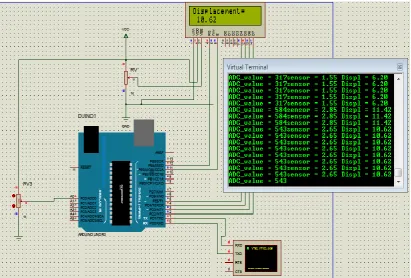
A throttle position (TP) sensor is a three-wire variable resistor called a potentiometer. The TP sensor signal voltage should be about 0.5 volt at idle and increase to about 4.5 volts at wide-open throttle (WOT). The TPS sensor gives the input to A0 input pin of arduino board. The arduino consists of atmega 168 IC it performs the operation on input signal provided by TPS . LCD is used to display that how much percentage of throttle valve is open i.e the output of the sensor. Virtual terminal shown in fig is used to display the output such as sensor value(10bit), sensor voltage and sensor displacement.
For implementing our project, we used various hardware which is readily available in the local market. Below here is given a list and short descriptions of various principal hardware used in our project:
3.1.1 Arduino Board Uno:
We chose to use arduino board uno to handle all computations and processes needed in our system.
The Arduino Board Uno has following features :
Features of the Arduino UNO:
Microcontroller: ATmega328
Operating Voltage: 5V
Input Voltage (recommended): 7-12V
Input Voltage (limits): 6-20V
Digital I/O Pins: 14 (of which 6 provide PWM output)
Analog Input Pins: 6
DC Current per I/O Pin: 40 mA
DC Current for 3.3V Pin: 50 mA
Flash Memory: 32 KB of which 0.5 KB used by bootloader
SRAM: 2 KB (ATmega328)
EEPROM: 1 KB (ATmega328)
Clock Speed: 16 MHz
3.1.2 LCD Display:
To obtain clear, real time video footage, we used the LCD Display.
Fig.3. 16*2 LCD Display
Features of the LCD Display:
Display format : 16 characters ´ 2 lines
Construction : TN/STN LCD panel, Bezel, Zebra and PCB.
Optional Edge/Array LED or EL back-light.
Controller : SED1278 or Equivalent.
5V single power input. (Special request for 3.3V driving, built-in DC/DC converter.)
Normal / Extended temperature type.
3.1.3Throttle Position Sensor Feature of TP Sensor
TP Sensor is used to monitor throttle position of throttle valve.
Sensor creates a voltage divider as the wiper moves along a fixed resistance.
Operating voltage range of aTPS is usually 0.5v to 4.8v
It is important for accelartion and deaccelaration compensation when the throttle is opened or closed.
TP Sensor is used to appoximate engine load by measuring throttle angle.
Throttle opening determine the engines power output.
The throttle position sensor reports the position of the gas pedals to the computer in a car
Fig.4. TPS Sensor
3.2. MAJOR SOFTWARE & LANGUAGES USED
The list of all the software used in our project is given below:
3.2.1. Proteus8.1:
We have many different simulation software for the simulation purpose Among these, proteus is the best , most popular and easy to handle and we can make pcb layout along with simulation.so it is easier for circuit designer to design a printed circuit board.
3.2.2 Arduino:
We have written programe in arduino code. It is the simple way to write a program for beginners. It is easily configurable . It saves time with code generation and ensure top code quality.
3.3. SETUP:
4.
SYSTEM FEATURES
This Model has the following Features.
Improves engines performance.
High load handling capacity.
Automatically update facility in ECU.
TPS helps in measuring tire pressure in future.
Engines with tps sensor gives good mileage with little carbon fumes.
TPS also controls the shifting of the gears.
TPS is used by ECM/PCM for fuel control, automatic transmission operation, a/c compresser cutout and clear flood mode
5.
Result
The fig 5 shows the simulation of the project on proteus software. Here we are using virtual terminator to display three parameters. the first parameter is ADC value which is the sensor value of 10 bit which varies from 1023. the second parameter is sensor value i.e the voltage reading from tps sensor which varies from 0-5V. the third parameter is displacement which is also displayed on the LCD that shows percentage of opening of throttle valve
Fig 5 Result on Proteus 8.1
6.
Conclusion
7.
References
[1]. https://www.arduino.cc/en/main/arduinoBoardUno [2]. https://en.wikipedia.org/wiki/Arduino
[3]. https://en.wikipedia.org/wiki/Throttle_position_sensor
[4]. Garrick, R.D., Sensitivity of Contact Electronic Throttle Control Sensor to Control System Variation, Society of Automotive Engineers (SAE) Technical Paper, 2006-01-0763, April 2006. http://delphi.com/pdf/techpapers/2006-01-0763.pdf
[5]. www.circuitstoday.com/interfacing-lcd-to-arduino
[6]. https://www.arduino.cc/en/Tutorial/LiquidCrystalDisplay
[7]. McKay, D., Nichols, G., and Schreurs, B., "Delphi Electronic Throttle Control Systems for Model Year 2000;Driver Features, System Security, and OEM Benefits. ETC for the Mass Market," SAETechnicalPaper2000-01-0556,2000
http://www.carprogrammer.com/Z28/PCM/FAQ/Delphi_Drive_by_wire_2000-01-0556.pdf
[8]. Zulkifli S. A., Asirvadam V. S ., Saad N., Aziz A. R. A., Mohideen A. A. M., "Implementation of Electronic Throttle -by-wire for a hybrid electric vehicle using National Instruments' CompactRIO and LABVIEW Real-time", IEEE, 2014, 978-1-4799-4653-2/14
[9]. Rostami M., Amiri P., "Designing of Automotive Engine Electronic Throttle Controller for EF7 Engine", Universal Journal of Electrical and Electronic Engineering 2(4), pp 145-151, 2014
[10]. Mingjiang H., Liqiao Q., " Optimizing Linearity of the Throttle Position Sensor Based on RBF-CMGA", Third International Symposium on Intelligent Information Technology Application, 978-0-7695-3859-4/09, 2009, pp 685-688.
[11]. Robert N. K., Loh, Thanom W., Pyko J. S., Anson L., "Electronic Throttle Control System: Modeling, Identification and Model-Based Control Designs", Scintific Research Engineering, 2013, 5, pp 587-600.