Remote Controlled Electronic Switching System
Project Report
Parlikar Alok Ulhas
Nishant Shrivastava
Shubham Shrestha Agrwal
Varun Khullar
Project Guide:
Dr. G. C. Nandi
Indian Institute of Information Technology, Allahabad
Abstract
We propose to install a system that shall enable an electronic switching device interfaced with a computer to be controlled remotely using a smart device. A client running on the user’s computer would connect to a central server, over an Internet connection. The user could then use a HTTP/WAP protocol from a smart device to connect to the central server, and issue requests to control his device.
Acknowledgment
The authors gratefully acknowledge the guidance provided by the project su-pervisor Dr G. C. Nandi throughout the development of the project.
The authors also wish to thank the other faculty members for their valuable suggestions and directions.
The authors also thank their batch mates for providing constant encourage-ment, support and valuable suggestions during the development of the project.
Candidate’s Declaration
We hereby declare that this project report titled ‘happyRC.NET Remote Con-trolled Electronic Switching System’ submitted towards the completion of Mini Project in 5thsemester of B.Tech(I.T.) in Indian Institute of Information
Tech-nology, Allahabad is an authentic record of our work carried out under the guidance of Dr. G. C. Nandi, Dean(Academics), IIIT Allahabad.
Date: December 3, 2004 Place: Allahabad
Parlikar Alok Ulhas Nishant Shrivastava
Shubham Shrestha Agrwal Varun Khullar
Certificate
This is to certify that the above declaration made byMr. Nishant Shrivastava,
Mr. Parlikar Alok Ulhas,Mr. Shubham Shrestha Agrwal andMr. Varun Khullar
is true to the best of my knowledge and belief.
Date: December 3, 2004 Place: Allahabad
Dr. G. C. Nandi Dean (Academics) Indian Institute of Information Technology, Allahabad
Contents
1 Introduction 1
1.1 What the problem is . . . 1
1.2 Importance of the problem . . . 2
2 State of the Art 3 3 System Architecture 4 3.1 ESS . . . 4
3.2 CSS . . . 5
3.3 Smart Device Client . . . 5
3.4 Architecture Notes . . . 6
4 How happyRC.NET works 7 4.1 Registering New User . . . 7
4.2 Activating Remote Device . . . 7
4.3 Showing Device State Change Interface . . . 7
4.4 Calculating New State Numbers . . . 7
4.5 Changing the State . . . 8
4.6 Logging Off . . . 8
4.7 Overall Activity Flow . . . 8
5 Design Issues 11 5.1 ESS Client Design . . . 11
5.2 CSS Server Design . . . 13
5.3 WebService Design . . . 13
6 Specific Technologies used 15 6.1 .NET Framework . . . 15
6.1.1 The Common Language Runtime . . . 16
6.2 .NET Remoting . . . 16
7 Conclusion and Future Scope 18 A User Manuals 19 A.1 Manual for the ESS Client . . . 19
A.1.1 Requirements . . . 19
A.1.2 Installing the Application . . . 19
A.1.3 Using the Program . . . 21
A.2 Manual for the CSS Server . . . 24
A.2.1 Requirements . . . 24
A.2.2 Using the Program . . . 24
A.3 Manual for the CSS Webservice . . . 26
B Hardware Details 28 C CSS-ESS Protocol Details 29 C.1 Getting Connected . . . 29
C.2 Security Paranoia and Encryption . . . 29
C.2.1 Two Types of Cryptography . . . 29
C.2.2 Security Attacks . . . 30
C.2.3 Security Solution in happyRC.NET . . . 30
C.3 The Request Reply Protocol . . . 31
C.3.1 Key Transfer . . . 31
C.3.2 Client Authentication . . . 31
C.3.3 Getting the Device Details . . . 32
C.3.4 Commanding the ESS . . . 32
C.3.5 Logging Off . . . 32
C.3.6 Exceptional Messages . . . 33
C.4 Protocol at a glance . . . 33
D Device Configuration File Format 34 E Developer Details – Writing a client for CSS 36
Bibliography 37
List of Figures
3.1 Architecture of the overall System . . . 4
4.1 Overall Activity Flow Diagram . . . 9
A.1 Installation of .NET Framework 2.0 . . . 20
A.2 ESS Client Installation Requirements Verification . . . 20
A.3 ESS Client Installation Security Warning . . . 21
A.4 ESS Application Login Screen . . . 21
A.5 ESS Application Settings Dialogue . . . 22
A.6 ESS Application – User Logged In . . . 23
A.7 ESS Application – Change Password . . . 24
A.8 CSS Login Screen . . . 25
A.9 Administration Tasks on the CSS . . . 26
A.10 Smart Device: Logging in . . . 26
A.11 Smart Device: Authentication Process . . . 27
A.12 Smart Device: Controlling Remote Device . . . 27
B.1 Hardware Circuit Diagram . . . 28
C.1 CSS-ESS Protocol Overview . . . 33
List of Tables
5.1 Division of project work among team members . . . 11
5.2 ESS Software Model Element Statistics Summary . . . 12
5.3 ESS Timeline Summary . . . 12
5.4 WebService Timeline Summary . . . 14
D.1 Device Configuration File Format . . . 35
Chapter 1
Introduction
Computers and the related technologies are becoming more and more ubiqui-tous. Various technical arenas in the field of Computer Science and Engineering, or Information Technology have come very near to the common people. The number of homes with Personal Computers1is gradually increasing. A day will
come, somewhere in the long future, when PC is referred to in the same class of “Food, clothing and shelter”. Improvements in the Networking technologies have fostered growth of very dense networks. Land line telephones have been becoming less and less popular and people now prefer communicating while on the move. ISPs are now laying down their own networks to provide broadband Internet access to customers.
When people have a good connectivity at their disposal, with tremendous power of mobile computing to supplement the same, we can think of “connecting their home appliances to the mobile phone”. With this, people would be able to turn on and off, and to some extent, control the appliances at their home even from a distant place. One of the very basic examples of an utility of this is – switching on the air conditioner in the room just some time before reaching home, so that the room is sufficiently cool by then.
1.1
What the problem is
The usefulness of a long range remote control to home appliances has no limits. A trivial setup facilitating such a thing would be to connect the home appliances, via a circuit, to a computer, then install a server software on the PC to export the device functionality on the internet, and then access the device from a smart device. However, this has certain disadvantages.
1. PC are not server systems. They should typically not run “server” soft-wares.
2. It is necessary that every PC has a global IP address that is recognized on the Internet. With the current stubborn setup of IPv4 and IPv6 not picking up momentum, this would be a major challenge. Users would definitely not be ready to shell out a lot of money for a leased IP address.
1Personal computers are referred to as PCs hereafter
V Sem Mini Project Report, Revision 1, December 3, 2004 2
Even if they are willing to, there is a very low limit to how many users can get such a privilege.
3. Keeping so many client server systems secure is a serious problem. With such unmanageable setup, maintaining the software system would be a mammoth task.
The problem then is, to install a system that would facilitate many clients to use its architecture and get their devices “online” very quickly, inexpensively, and with minimal effort.
1.2
Importance of the problem
A commercial implementation of the idea in this project could speed up the Home Automation activities. Remote access has always proved to add to the utility of any existing setup. Toys, Televisions, Music Players, all have started having a remote control, why not switches?
Chapter 2
State of the Art
A Remote Control is perhaps the most popular gadget today. Right from the intense creativity of remotely controlling laser chip markers to the highly de-structive remotely ignitable bombs, from the pins to the planes, remote control is not only occupying a omnipresence state, but is also enhancing its scope and domains.
We have had InfraRed Remote Controls, which work over very short dis-tances, and RadioWave Remote Controls, which work over larger distances. However, something fundamentally common with all these controls is that the transmitter and receiver should both use some kind of wireless waves. Thus, the range of the control is limited.
If some control is desired to be remote across the globe, the technology required intensively uses satellites, and thus, such a control has not been able to become so popular. The INTERNET is more than just a world wide web. Mobile phones are the gadgets of this generation. Remote control based on Internet on mobile phones seems to be satisfactory quench of the desire.
There have been attempts to write such implementations earlier. However, most of them were targetted towards specific devices. The need is to write generic device control applications.
Chapter 3
System Architecture
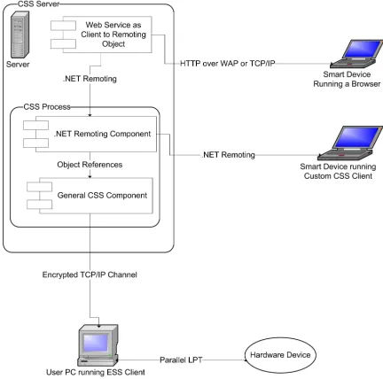
[image:12.595.187.403.363.577.2]The happyRC.NET system consists of three main parts, namely theEnd User Server System(ESS), the Central Server System(CSS), and the Smart Device Client. Figure 3.1 shows the logical structure of these parts, and an outline of the components therein.
Figure 3.1: Architecture of the overall System
A brief description of these components is as follows:
3.1
ESS
The End user Server System is a client1application that runs on the user’s PC.
It takes authentication details from the user and uses an encrypted TCP/IP
1The wordServer System is a misnomer. The Client installed on ESS acts as if there was
a server exporting the device functionality
V Sem Mini Project Report, Revision 1, December 3, 2004 5
channel(See Appendix C) to talk to the CSS. It has a configuration file that contains details about the controllable hardware attached to the PC. It is the job of the ESS to understand commands from the CSS and change the device state accordingly.
3.2
CSS
The Central Server System is the heart of the art. It has three roles to play, and therefore has threecomponents that export various important functionalities.
General Component The General CSS Component is where most of the func-tionality resides. It is the job of this component to receive connections from various ESS PCs, and maintain their authentication states. This maintains a lookup information about exactly which ESS particular users are connected from, and what the device configuration of their system is. It shares its memory space with the Remoting component described next. It is the job of this component to proxy requests from the remoting component to the ESS system, and return the occurrence of a success or failure.
Remoting Component This component is a stub for .NET Remoting2calls.
It gives a reference to an object which has proxy functions written to allow Remoting clients to call functions of the General Component. Every connection to this component instantiates a new object which maintains the state (authentication, etc.) of the client. Methods in this object wait for a reply from the General Component and send the reply back to the client.
Web Service To facilitate easy HTTP3 access from smart clients, this
ponent becomes crucial. It sits on a web server (running IIS) and com-municates to theGeneral Component via theRemoting Component. The job of this component is to maintain authentication states over the web. It should ask theRemoting Component to provide the description of the user’s device. It should then parse the description out, and display an interface that can change the device state.
Put together, these components build up the CSS System which can provide facilities for any user to register his device online, and later on, use browser complaint smart client to remotely control the same.
3.3
Smart Device Client
This client is the tool that would act as a Remote Control to the users. This interacts with the CSS and commands the ESS to change the state of their device at a remote location. Figure 3.1 shows two kinds of these clients. They are classified on the basis of howthin clients they are.
V Sem Mini Project Report, Revision 1, December 3, 2004 6
Smart Devices Running Browsers This category includes devices that are very thin in functionality. Typically, these include mobile phones, Wireless PDAs, etc. They do not have the capability of running large programs, and ship with an operating system that provides a minimal browsing func-tionality. All that these can do is display primary interfaces, and request simple form submitted by the users. They need to interact with theWeb Service component of the CSS in order to facilitate service.
Smart Devices Running CSS Client Some devices have more features than plain smart devices, and are smarter then we think. Pocket PCs that run operating systems like Microsoft Windows CE have capabilities of running custom programs. A custom made CSS client(See Appendix E) can be in-stalled on these devices so as to customize user interfaces. These devices can skip the Web Service component and directly interact with the CSS using .NET Remoting. Clearly, Laptops and Computers are smarter then even pocket PCs, and they can fall into this category.
3.4
Architecture Notes
The happyRC.NET system uses a Client-Server architectural model. With a second look, we find that it comprises of a single server that serves multiple clients of two types viz., ESS and smart devices. It should be noted that ESS and smart devices have a one to one relationship and they share the user’s identity in common. Although one ESS can be controlled using many different types of smart clients, two of these clients can not talk simultaneously with the same ESS, for reasons of atomicity and consistency of operations.
The ESS is connected to the user’s device using a parallel (LPT1) port. This was preferred over a serial port so that we can work with 8 bits simultaneously rather than memorise bits received from the serial port and work once all of them are received. This definitely speeds up the operations.
The communication between CSS and ESS works on a Request-Reply proto-col that is encrypted withsymmetric cryptography to avoid malicious attempts of hack, man in the middle, or eavesdrop replay attacks. (See Appendix C.
The General Component and Remoting Component of the CSS share the same memory as they run in a single instance of the same application process. Communication between these is by simple means of object references.
Chapter 4
How happyRC.NET works
As with almost any other computer based system, the working of happyRC.NET begins with the process of Installation followed by the successive use. Instal-lation of the ESS on the user’s PC includes configuration of the device.(See Appendix A The brief working strategy of the system is outlined below.
4.1
Registering New User
After proper installation of the ESS client on the user’s PC, the users need to get authentication account on the CSS. Once the request for a new identity on the CSS is granted by the administrator, an entry of the username and its corresponded password is appended in the authentication database1.
4.2
Activating Remote Device
When the users log in to the system using the ESS, the ESS connects to the CSS and verifies their identity. Having done that, the CSS requests the ESS to send the device details. The CSS parses the configuration file into an serialized object and sends it over to the CSS. The device is now ready to be remotely controlled
4.3
Showing Device State Change Interface
The users on the smart clients need to be given an interface for changing the device state. To facilitate this, the client request the CSS to send them the device configuration details. These details are parsed based on the type and groups of inputs and the interface is displayed.
4.4
Calculating New State Numbers
The device states are classified into groups. For every group, there is a union policy, like AND, OR, XOR. Every state is represented by a byte, and when in
1The database could well be a flat file.
V Sem Mini Project Report, Revision 1, December 3, 2004 8
groups, these bytes can be combined into one. Thus, if the policy of a certain group isOR, a bitwiseORwould be performed among all the states in that group. This newly generated number is the state of that group.
For every such group specified in the configuration file, a new state number is calculated. These state numbers are ordered by their group numbers, say 1,2,3, and stored for further processing.
Group Zero is a special group, where there is no union policy. Every state in this group is sent as if it were in an independent group and the state numbers of all states in this device are added to the end of the stored list.
4.5
Changing the State
For every state number generated by steps in section 4.4, a request is sent to the CSS to write the same onto the device. The CSS in turn forwards the request to the ESS which does the actual action of writing thecommand to the parallel port. Based on whether the action returned success or failure, the users need to be notified.
4.6
Logging Off
When the users log off from the smart clients, no significant state changes occur in the CSS. The ESS still remains connected, and users can again use the smart client for further communication with device.
However, when the uses log off from the ESS, the CSS discards all dynamic entries for this connection, and if some smart client tries to communicate with that discarded identity, they are returned error.
4.7
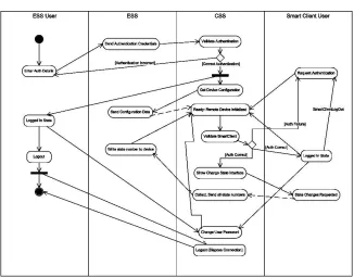
Overall Activity Flow
Along with the activities mentioned in the earlier sections, there are minute details that need to be described in order to understand how exactly the system proceeds with the work flow. Figure 4.1 shows an activity flow diagram of the system.
Here is an enumerated description of the activities. The enumeration shows the primary activity flow. The flow might change a little in certain extended use cases.
1. The user interface of the ESS system would be used by the user to enter his authentication credentials.
2. The ESS program would set up a communication channel with the CSS, thereby connecting and verifying the user’s details.
3. If the authentication succeeds, the user is notified that his device is ready to be controlled remotely.
V Sem Mini Project Report, Revision 1, December 3, 2004 9
Figure 4.1: Overall Activity Flow Diagram
5. ESS communicates the details of the device to the CSS on the already established channel, and sets up callbacks on the CSS, so that it can receive interesting information from the same.
6. The CSS, when it receives the device details, it sets up a set of functions for the device, on the web service, to be remotely invoked.
7. The CSS maintains a table containing entries of which authenticated user is using which instance of the CSS-ESS messenger program.
8. A user can switch on his smart client. The client knows the CSS, or else, asks the user about the address of the CSS.
9. If the client is able to establish a connection to the CSS, it asks authenti-cation details to the user.
10. The client calls the initialize function on the CSS by parameterizing it with the authentication details.
11. The CSS verifies the authentication and if the client is affirmatively iden-tified, it sends the device description to the client, along with the current state of the device, if asked.
12. The client extracts a form out of the obtained description and displays it to the user.
V Sem Mini Project Report, Revision 1, December 3, 2004 10
14. For each request that the client makes to the CSS, the CSS sends a word to the ESS that has to be written on the parallel port of the same.
15. The ESS acknowledges the CSS which in turn nods to the client.
16. The client maintains state using some form of cookies and repeatedly keeps asking user for further change in the circuit. The user can choose to logout or change his password.
17. Once logged out, there are no changes on the CSS and the ESS.
18. However, the user can choose to disconnect his circuit by closing the ESS application. In such a case, the CSS would dump all the connection details, including the device details of the disconnected ESS, into garbage.
Chapter 5
Design Issues
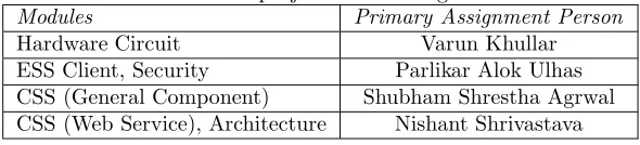
[image:19.595.149.444.376.443.2]In this chapter, we would give details about how the project was conceived and built, i.e. the Analysis and design phase. Because the project team consists of four members, the work was distributed in blocks of modules as described in Table 5.1.
Table 5.1: Division of project work among team members
Modules Primary Assignment Person
Hardware Circuit Varun Khullar ESS Client, Security Parlikar Alok Ulhas CSS (General Component) Shubham Shrestha Agrwal CSS (Web Service), Architecture Nishant Shrivastava
Because the modules have been designed almost independently, the design issues are separately sectioned.
5.1
ESS Client Design
The ESS client task was subdivided into the following activities.
Interacting with the Hardware This task involved writing a byte into the parallel port. TheManaged Runtimeof the .NET platform that was being used to develop the project does not allow “unsafe” I/O calls like this, and hence a DLLImport followed by a call to one of the entry points in the DLL was to be performed. The Windows documentation mentions how the Kernel API can be used to interact with external devices.[Mic03] The other essential thing was to tell the software, details of the hardware connected. To do this, a configuration file format was formulated. The format allows access to devices with up to 256 states. More details of the format can be found in Appendix D.
Communicating with the CSS This task involved formulating a protocol that works over TCP/IP channel, and then an implementation of the same. The protocol was formulated taking a skeleton of SMTP like Request-Reply protocols. Details of the protocol and how the transmission is suf-ficiently strongly encrypted can be found in Appendix C.
V Sem Mini Project Report, Revision 1, December 3, 2004 12
The User Interface This task involved creating a GUI for the user to interact with the system. Some salient features of the GUI are:
1. Strict validation of inputs 2. Based on a state machine 3. User friendly errors
4. Use of registry to save settings. The key used for the purpose is HKEY\LocalMachine\Software\happyRC
The ESS was designed in a round trip engineering mode. To start off, we had a basic class diagram, with bare functionality built in. Then an automated code generation was done. That code was edited, and the diagrams modified ac-cordingly. The class diagram was always synchronized, and many times, adding more functionality was done from within the diagram. The toolsMicrosoft Vi-sual Studio .NET 2005 andMicrosoft Visio Enterprise Architect 2005 were very handy in this kind of approach.
Table 5.2 shows the Element Statistics Summary of the ESS Software. It should be noted that the numbers in the table also count the classes and packages that the .NET provides. For example, every object is a specialization of the
[image:20.595.173.399.393.511.2]Objectclass, and hence the counter forGeneralizations is that high.
Table 5.2: ESS Software Model Element Statistics Summary Number of Interfaces 17
Number of Classes 41 Number of Data Types 2 Number of Attributes 81 Number of Parameters 62 Number of Operations 53 Number of Generalizations 45 Number of Packages 11 Number of Subsystems 1
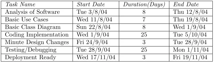
[image:20.595.124.470.588.691.2]Table 5.3 shows the Timeline Details imported as text from the Grant Chart. Dates specified herein are notAssigned Dates, but areActual dates. (That is, these area posteriori Grant Chart Details).
Table 5.3: ESS Timeline Summary
Task Name Start Date Duration(Days) End Date
Analysis of Software Tue 3/8/04 8 Thu 12/8/04 Basic Use Cases Wed 11/8/04 7 Thu 19/8/04 Basic Class Diagram Sun 22/8/04 8 Wed 1/9/04 Coding Implementation Wed 1/9/04 25 Tue 5/10/04 Minute Design Changes Fri 24/9/04 3 Tue 28/9/04 Testing/Debugging Tue 28/9/04 25 Mon 1/11/04 Deployment Ready Wed 17/11/04 3 Fri 19/11/04
V Sem Mini Project Report, Revision 1, December 3, 2004 13
5.2
CSS Server Design
The CSS Server has following functions to perform:
Interacting With the ESS The implementation of the protocol formulated with the ESS was an obvious task. However, certain issues which dif-fered from the ESS was the presence of multiple ESS clients. To take care of many clients, the CSS had to be implemented as a state machine based program. Asynchronous read functions were made for robust state machine.
Communicating via .NET Remoting .NET remoting was used to export the functionality of the General CSS component to the smart client world. TCP channel is used for the communication. The exported functionality is documented in Appendix E.
The user Interface The task involved creating the GUI for the user to in-teract with the system. The GUI is also implemented as a state based machine.
The CSS was designed using the prototyping principle. A basic prototype was first built, and more functionality was added in increments.
5.3
WebService Design
Thought behind the Design
The basic aim of this project is to provide a method to general users who don’t want to go into the technical details and yet reap the benefits of technologi-cal advances to their benefits.This basic aim couldnot have been fulfilled if it required some expensive WindowsCE enabled mobile phone which costs some-thing in excess of 40,000 rupees to remotely controll the user’s home appliances. Therefore the method to be implemented on the mobile devices had to be some-thing on the lines of a web service which could be access from any Internet enabled mobile phone.
Choice of Technology to use
V Sem Mini Project Report, Revision 1, December 3, 2004 14
Interaction with the CSS
The basic interface was made in ASP.Net using Mobile controls with C# as the script powering the ASP.Net page.The interaction with the CSS was using .Net Remoting by creating a Client Activated Object over a TCP channel with the CSS.[Gri02]
Backend Implementation Summary
[image:22.595.124.472.361.453.2]A .Net Remoting Client Activated TCP channel is created with the CSS as soon as the user provides his login ID and password. If the username and the password match with those in the Database at the CSS, the user is successfully authenticated. The CSS on request transmits to the Web Server data about the state of the User’s ESS and the groups and the policy associated with groups of the User’s appliances. After receiving the request of the user, as to what changes he wishes to make to the final state of the appliances, the final state of the end System is calculated and the words to output to the end system are transmitted to the CSS which in turn sends the data to the ESS.
Table 5.4: WebService Timeline Summary
Task Name Start Date Duration(Days) End Date
Chapter 6
Specific Technologies used
6.1
.NET Framework
The .NET Framework is a new computing platform that simplifies application development in the highly distributed environment of the Internet.[Mic03] The .NET Framework is designed to fulfill the following objectives:
• To provide a consistent object oriented programming environment whether object code is stored and executed locally, executed locally but Internet-distributed, or executed remotely.
• To provide a code-execution environment that minimizes software deploy-ment and versioning conflicts.
• To provide a code-execution environment that guarantees safe execution of code, including code created by an unknown or semi-trusted third party.
• To provide a code-execution environment that eliminates the performance problems of scripted or interpreted environments.
• To make the developer experience consistent across widely varying types of applications, such as Windows-based applications and Web-based ap-plications.
• To build all communication on industry standards to ensure that code based on the .NET Framework can integrate with any other code.
The .NET Framework has two main components: the common language runtime and the .NET Framework class library. The common language runtime is the foundation of the .NET Framework. One can think of the runtime as an agent that manages code at execution time, providing core services such as memory management, thread management, and remoting, while also enforcing strict type safety and other forms of code accuracy that ensure security and robustness. In fact, the concept of code management is a fundamental principle of the runtime. Code that targets the runtime is known as managed code, while code that does not target the runtime is known as unmanaged code. The class library, the other main component of the .NET Framework, is a comprehen-sive, object-oriented collection of reusable types that you can use to develop
V Sem Mini Project Report, Revision 1, December 3, 2004 16
applications ranging from traditional command-line or graphical user interface (GUI) applications to applications based on the latest innovations provided by ASP.NET, such as Web Forms and XML Web services.
The .NET Framework can be hosted by unmanaged components that load the common language runtime into their processes and initiate the execution of managed code, thereby creating a software environment that can exploit both managed and unmanaged features. The .NET Framework not only provides several runtime hosts, but also supports the development of third-party runtime hosts.
6.1.1
The Common Language Runtime
Compilers and tools expose the runtime’s functionality and enable you to write code that benefits from this managed execution environment. Code that you develop with a language compiler that targets the runtime is called managed code; it benefits from features such as cross-language integration, cross-language exception handling, enhanced security, versioning and deployment support, a simplified model for component interaction, and debugging and profiling ser-vices.
To enable the runtime to provide services to managed code, language com-pilers must emit metadata that describes the types, members, and references in your code. Metadata is stored with the code; every loadable common lan-guage runtime portable executable (PE) file contains metadata. The runtime uses metadata to locate and load classes, lay out instances in memory, resolve method invocations, generate native code, enforce security, and set run-time context boundaries.
The runtime automatically handles object layout and manages references to objects, releasing them when they are no longer being used. Objects whose lifetimes are managed in this way are called managed data. Garbage collection eliminates memory leaks as well as some other common programming errors. If your code is managed, you can use managed data, unmanaged data, or both managed and unmanaged data in your .NET Framework application. Because language compilers supply their own types, such as primitive types, you might not always know (or need to know) whether your data is being managed.
The common language runtime makes it easy to design components and ap-plications whose objects interact across languages. Objects written in different languages can communicate with each other, and their behaviors can be tightly integrated. For example, you can define a class and then use a different language to derive a class from your original class or call a method on the original class. You can also pass an instance of a class to a method of a class written in a different language. This cross-language integration is possible because language compilers and tools that target the runtime use a common type system defined by the runtime, and they follow the runtime’s rules for defining new types, as well as for creating, using, persisting, and binding to types.
6.2
.NET Remoting
V Sem Mini Project Report, Revision 1, December 3, 2004 17
across the entire world. One can build client applications that use objects in other processes on the same computer or on any other computer that is reachable over its network. One can also use .NET remoting to communicate with other application domains in the same process.
Chapter 7
Conclusion and Future
Scope
In this report, we described happyRC.NET as a project that helps us talk to devices that are connected to a remote computer. A careful implementation of the idea suggested by the project can prove to be very beneficial in promoting home automation and similar activities. This project can be considered as a proof of concept – the concept that it is possible to mobilize the control of appliances.
What this project does in the ESS, i.e. interaction with the hardware, could as well be performed on an embedded system. Agreed, IPv6 is taking time to gain dominance, but assuming that in such a world, there is no dearth of IP addresses, almost every device could have an IP address, and anEmbedded ESS
of its own, to make life of people even more easier. What is aRemote Control
today, would get replaced by aMobile Control.
This project lacks support for devices that have more than 256 states. More over, this can control only state based devices. There are some devices that are activity based, not state based. For most needs, changes in the configuration file format would suffice for getting a proper support for the required device. For example, these changes could be – adding new action types, or more group policies, etc. However, in rare cases, the application might have to be slightly restructured.
Appendix A
User Manuals
The user manual of the ESS, CSS, and the Interface.
A.1
Manual for the ESS Client
The ESS Client is a light weight application taking about 96KB on the disk. This section deals with the installation and usage details of that application.
A.1.1
Requirements
Although efforts were made to keep the ESS Client as light as possible, it still has a set of minimum system requirements, as follows:
• Microsoft Windows1 98 and Later.
• .NET Framework version 2.0 or later
• Network Connection
• Parallel Port (LPT1) on the host system
A.1.2
Installing the Application
Instead of using the default InstallShield types of installation, the ESS client has been deployed as aClick Once application. The deployment folder would contain a “Setup” utility which can be used to directly run the application. Below are given the basic installation steps.
1. Locate the Installation Folder. If the folder resides on a network share, copy it to your local disk.
2. Run the fileSetup.exe.
3. If you get a screen as shown in Figure A.1, please read the license carefully and click theAcceptbutton to proceed. This error had come because you had not installed the .NET Framework 2.0, and hence, it required to be
1It is possible to port the client to other operating systems like Linux, however the
appli-cation as a part of this project compiles, but does not run on Linux
V Sem Mini Project Report, Revision 1, December 3, 2004 20
[image:28.595.205.387.161.379.2]installed. Once you are done with the installation, restart your system and continue with the installation of this application.
Figure A.1: Installation of .NET Framework 2.0
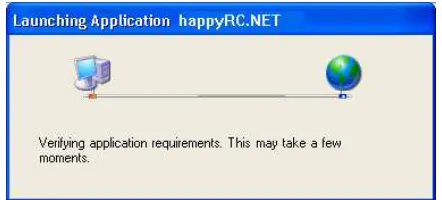
4. The installation would check for system requirements, during which it would show a progress splash screen as shown in Figure A.2.
Figure A.2: ESS Client Installation Requirements Verification
5. If you get a dialogue as shown in Figure A.3, you must be running the setup from a network location. Make sure you have copied the installation files to your local system.
6. If your system had met the requirements of the application, it would get successfully installed. A shortcut would be added to the Start Menu, at the locationAll Programs -> IIITA. You can use this shortcut to run the application.
[image:28.595.186.407.453.553.2]V Sem Mini Project Report, Revision 1, December 3, 2004 21
Figure A.3: ESS Client Installation Security Warning
A.1.3
Using the Program
Running the Application
• The application installation creates a desktop shortcut for the application. You can run the application from the desktop.
• You can also run the application from the start menu. The shortcut would be installed at the location: Start -> All Programs -> IIITA -> happyRC Client.
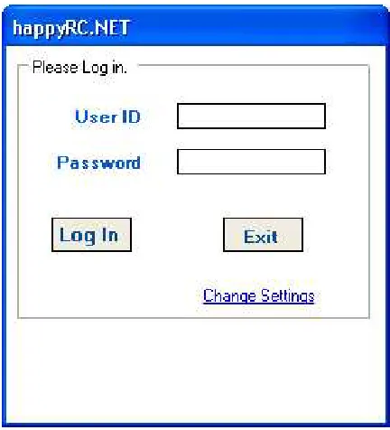
When the application runs, you would get a screen as shown in Figure A.4.
[image:29.595.188.404.429.667.2]V Sem Mini Project Report, Revision 1, December 3, 2004 22
Changing the Settings
Before using the program, you must know the location of the CSS server and the location of the configuration file for your device. To change the existing settings,
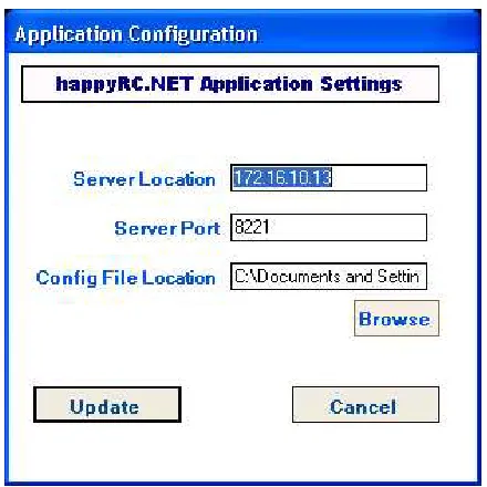
[image:30.595.187.407.220.440.2]1. From the Login screen, (Figure A.4) click the “Change Settings” link. You would be presented with a form that looks as in Figure A.5.
Figure A.5: ESS Application Settings Dialogue
2. Enter the CSS server’s IP address or host name in the first field.
3. Enter the CSS server’s port number (default: 8221) in the second field.
4. In the third field, select the location of the device configuration file on your system.
5. Once you click theUpdate button, the application would try to verify the settings. If any of the settings is incorrect, a red blinking icon would be placed next to that field. Hover the mouse over that box to see what error was encountered, and take appropriate corrective steps.
6. If the updation is successful, the application would return back to the login screen.
Logging in
1. At the login screen (Figure A.4), enter your authentication credentials.
V Sem Mini Project Report, Revision 1, December 3, 2004 23
3. On clicking the Login button, the application would try to log you onto the CSS server. If the authentication fails, you would get a notification of the same.
4. If the authentication times out, you would be notified about the same too. You may then try authenticating again.
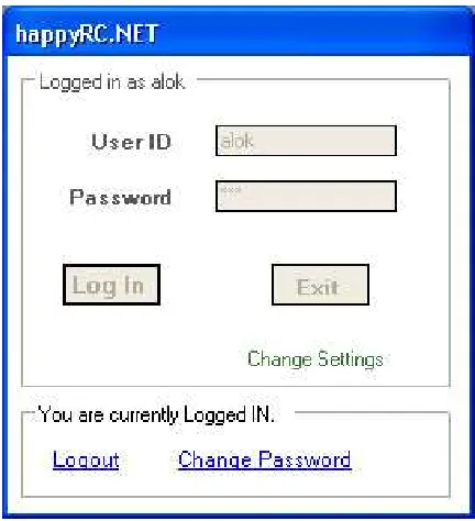
[image:31.595.188.404.236.473.2]5. If the authentication is successful, the application displays the “Logged In” dialogue as shown in Figure A.6.
Figure A.6: ESS Application – User Logged In
Changing the Password
1. Follow steps in Section A.1.3 to log on from the ESS client. This would take you to the Logged In screen(Figure A.6).
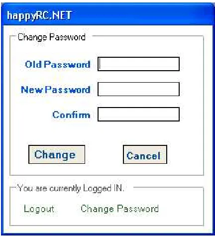
2. Click the Change Password link. You would be taken to the password change interface as shown in Figure A.7.
3. Enter the old and new passwords. Also enter the new password again, for confirmation, and click theChange button. If the password change was successful, you would be taken back to the Logged In Screen (Figure A.6).
V Sem Mini Project Report, Revision 1, December 3, 2004 24
Figure A.7: ESS Application – Change Password
Logging Out
From the Logged In Screen (Figure A.6), click theLogoutlink in order to log out. The application will ask for a confirmation during logout. ClickOKto continue with the logout. You would be presented with the Login screen (Figure A.4) again.
A.2
Manual for the CSS Server
The CSS is a server application that runs on a system on theInternetand allows many end users to connect to the their devices attached through the ESS. This section deals with the usage details of the server.
A.2.1
Requirements
The CSS provides many to many connectivity for its users, and thus it is required that the underlying OS of the system supports this heavy network load. Here is a set of minimum requirements.
• .Net Framework 1.1 or Higher
• Windows Server 2003 (Recommended) or Windows XP (Professional)
A.2.2
Using the Program
V Sem Mini Project Report, Revision 1, December 3, 2004 25
[image:33.595.190.320.170.305.2]the server and perform any of the admin tasks for which GUI interface. The administrator can also start the server which will start the server on request of client will connect to ESS Client.
Figure A.8: CSS Login Screen
Logging in
1. Start the application.
2. Enter userId and password in the login screen.
3. If your credentials are authentic, and you have administrator rights as-signed, the system would log you in.
Logging out
The application would log the administrator out at the click of the Logout
button.
Starting the Server
1. Start the application.
2. Log in with admin rights
3. Click on start server button after logging in.
Note: The server will keep running until you don’t close the application or you do not stop the server. Logging out would not stop the server.
Stopping the Server
If the server is running, and you are logged in, you can click the Stop Server
V Sem Mini Project Report, Revision 1, December 3, 2004 26
User Management
1. Log in as told above.
2. Click theAdmin task button after logging in.
3. Select the appropriate activity, from those shown in Figure A.9.
[image:34.595.190.318.236.369.2]4. Write the user’s name for performing that activity and clickOK.
Figure A.9: Administration Tasks on the CSS
A.3
Manual for the CSS Webservice
The user interface of the webservice provides strict validation of inputs and generates proper messages reflecting the state of the connection. The user is asked to authenticate at the first page where he sees a Login Screen prompting for a Username and a Password to initiate the communication. (See Figure A.10)
[image:34.595.168.426.552.700.2]V Sem Mini Project Report, Revision 1, December 3, 2004 27
[image:35.595.170.425.188.334.2]If Authentication fails, he is asked to re-enter his username and password. On Authentication with a valid Username and Password, he can choose either to change his password or to Control the devices thus fulfilling his dream of Home Automation. See Figure A.11
Figure A.11: Smart Device: Authentication Process
On successful change of password, user is asked to relogin with the new password. If he selects to Control his devices screen generates the list of the appliances connected to his end system and by means of checkboxes and Text input, he inputs the final state of the end system device. On selecting the selection Option, the device List is shown on the Mobile Screen. User makes his selection and sends the request back to the server. (See Figure A.12)
Figure A.12: Smart Device: Controlling Remote Device
[image:35.595.171.426.452.605.2]Appendix B
Hardware Details
The following components were used to build the hardware.
• Relays- OMROM 5A/25 V DC : 10A/220 V Ac : 12V DC
• Optocouplers- 4N35 1.2v to drive.
• Resistors- 1 kilo ohm.
• DC Adaptor or Transformer -12V.
• Switch and socket, Bulb
[image:36.595.161.437.550.654.2]The relay is used as a electromechanical relay. The circuit consists of four independent sub-circuits which in turn can run four different aplliances. The parallel port gives a potential of 3.3v to 3.5v which has been used to drive the optocoupler. The optocoupler is used as a switch for a 12v DC supply (given by a transformer). This 12V is being used to Switch on the relay. The relay is connected to 220 volts AC power supply. This power supply is now controlled by parallel port and can be used to run various appliances.
Figure B.1 shows the circuit diagram of the connection.
Figure B.1: Hardware Circuit Diagram
Appendix C
CSS-ESS Protocol Details
This Appendix mentions details about the protocol that the CSS and ESS use to talk to each other. A one liner description of the protocol is ”Request Reply protocol over Encrypted TCP/IP Channel”. The following sections explain how different issues are tackled in the protocol.
C.1
Getting Connected
The CSS has a General Component that listens to a specific TCP port on the server machine. The ESS Client must know this port number in order to establish a connection. Having known the same, it establishes a regular TCP connection using Network Sockets.
C.2
Security Paranoia and Encryption
C.2.1
Two Types of Cryptography
There are two basic kinds of cryptography[Tan00]. InSymmetric Cryptography, the two entities that wish to communicate use the same key. Algorithms like DES are used to encrypt and decrypt a given text, and this shared key is required for the purpose. In Asymmetric Cryptography, every entity has a pair of keys containing, one public key and other private key. Algorithms like RSA are used to encrypt the text. To send encrypted data to someone, his public key is used in the encryption algorithm. This text can not be decrypted by any other key than the corresponding private key.
The performance of symmetric key cryptography is better as compared to asymmetric key cryptography. However, the concept of “shared key” presents a problem. Sharing the key becomes a crucial issue. One has to create this key and send it to the other. If some person taps their connection, the beauty of this algorithm gets pretty useless. Sharing keys1 is quite better with public key
cryptography, one just needs to send the public key. However, there still present problems of security attacks.
1Generally, the encryption algorithms used are symmetric, but the key transfer is done by
encrypting the symmetric key in a public key encryption.[Sta02]
V Sem Mini Project Report, Revision 1, December 3, 2004 30
C.2.2
Security Attacks
Trivial Network Tapping
This kind of an attack can occur if the symmetric key is transferred over an insecure channel. Once an evesdropper gets hold of the key, all algorithms become very useless.
Log and Replay
Algorithms that have their keys hard coded are vulnerable to this attack. Be-cause the key for their encryption and decryption are same at all times, an evesdropper can record a transaction between two parties by tapping the net-work line. He might not be able to understand their conversation, may be, because he might not have the keys. However, he can send back the same data and pretend to be the authorized user who was sending that data earlier. The other party can not distinguish between the initial transaction and the replay attack.
Man in the Middle
The biggest problem even with public key cryptography is this attack. Instead of just tapping the network line between two parties, the evesdropper this time sits in between them. Right from when the key transfer takes place, this evesdropper proxies the connection between the parties, and also proxies for the public keys. He can thus not only understand the conversation between the parties, but also
change the same without the understanding of any of the parties.
C.2.3
Security Solution in happyRC.NET
The above mentioned attacks were carefully avoided in the security implemen-tation of this system. A synopsis of the encryption algorithms is explained followed by the details of how the above attacks are avoided.
The Solution Details
• The system employs symmetric (shared key) cryptography
• The Rijndeal algorithm is used for the encryption.2
• The shared key is not fixed, but is generated dynamically.
• The key is generated from two salts – a random string, and the user’s password.
Defense against Attacks
It is important to note the following.
• The user’s password is known to the ESS as the user is going to enter it for authentication purposes.
V Sem Mini Project Report, Revision 1, December 3, 2004 31
• The user’s password is known to the CSS because it has a password database.
• No one else knows the user’s password. (The user is supposed to keep it secret)
A Symmetric Cryptography algorithm begins with sharing of the key. The key that we are using is generated from two parts, one of which is known to both the ESS and CSS. After the connection, CSS generates a random string and transmits it plain text to the ESS. Using this string and the password, both of them generate a “shared” key.
1. Because any evesdropper does not know the user’s password, even if he reads the random string, he can notgenerate the key that is shared by CSS and ESS.
2. Because the generated key depends on a random string, which ought to be different for every connection, the “shared key” is different for every connection, and thus, the evesdropper can not replay his transaction log onto the network.
Thus we see that the attacks of tapping, Log-Replay and man in the middle are defended by the system.
C.3
The Request Reply Protocol
The following text describes the messages that are passed between the CSS and ESS. Please note that the text written in Typewriter Styleis an encrypted message, and any message that is transferred plain text is written in Slanted Text. Also note that every message ends in a Line Feed Character(\n).
C.3.1
Key Transfer
After connection, the ESS initiates the dialogue. The first messages between the systems is as follows:
ESS: KEY userName
CSS: KEY 50meR4nd0m5+r1ng
When CSS receives the username, in the first message, it first calculates a random string and sends it back to ESS. It then retrieves the user’s password from the database and using this and the random string, generates the shared key. When ESS gets the second message, it uses the user provided password and this random string to compute the shared key. Thus, at the end of this transaction, both share the same key.
Note: If the user enters an incorrect password in the ESS interface, at the end of this process, the CSS and ESS would have different keys. This is handled during the authentication
C.3.2
Client Authentication
V Sem Mini Project Report, Revision 1, December 3, 2004 32
ESS: AUTH userName pA55w0rd
CSS: OK
OR
ESS: AUTH userName pA55w0rd
CSS: ERR
The ESS sends an encrypted text containing the username and password of the user. If the password was correct, the message could be decrypted by the CSS. In such a case, it would reply with a plaintext OK saying that the authentication is done. If it is not able to decrypt, it understands that the ESS had a different shared key because the user entered incorrect password, and hence returnsERRin plain text.
Note: The CSS replies to the authentication request in plain text. This was necessary because if the user has entered incorrect password, it would not be able to decrypt even the ERR response, and there would be a infinite loop in the state machine.
C.3.3
Getting the Device Details
After successful authentication, the CSS requests the ESS to send it the descrip-tion of the device connected. The ESS has an object containing the descripdescrip-tion. It is serialized and base64-encoded and returned as a reply as follows.
CSS: DESC
ESS: DESC base-64 encoded serialized object
The serialized object is typically XML, and contains many line breaks. In the protocol, every message terminates with a linefeed, and thus, the serialized text can not be passed as it is. Hence, the base 64 encoding is applied to the same.
C.3.4
Commanding the ESS
When the CSS gets requests from the smart client, for changing the device state, it has to tell the ESS to write some byte to the port. Following is the dialogue that takes place.
ESS: WRITE byte
CSS: OK
OR
ESS: WRITE byte
CSS: ERR
Given the byte, the CSS attempts to write it to the port. In most cases, the call succeeds, and CSS replies withOK. However, in some cases, the write to the port fails. For example, if someone maliciously tried to write a number with value more than 255 (maximum for a byte), then this call would fail, and ESS would reply in an error.
C.3.5
Logging Off
The user on the ESS may choose to log his client off. It is the job of the ESS to notify the CSS about the action and then close the network connection.
V Sem Mini Project Report, Revision 1, December 3, 2004 33
The ESS closes the socket immediately after this transfer. The CSS should close its end too, after it gets the notification.
C.3.6
Exceptional Messages
It might happen that even after the proper authentication, etc. of the ESS with the CSS, some error might creep in. This should not happen with the actual clients, but some malicious hacker might attempt sending messages that are out of context. To handle such situations, the CSS sends the following message whenever it does not understand what the message was.
CSS: EMERGENCY
Note that an invalid operation usually results in just ERR. Only in certain exceptional cases, like invalid description will this message be used. The CSS would close the connection after sending this message. The ESS notifies a fatal error on getting this response from the CSS.
C.4
Protocol at a glance
[image:41.595.160.439.390.685.2]The earlier section describes that the protocol uses the commands KEY, AUTH, DESC, WRITE, OFF, EMERGENCY, OK, and ERR. Figure C.1 shows a graphical overview of the protocol.
Appendix D
Device Configuration File
Format
This Appendix discusses the format for the file that specifies details about the hardware connected to the ESS. This Configuration File can be located any where on the system that has ESS installed. Path to the correct file can be set from the ESS program.
ThisConfiguration File is a tab separated text file. There are two sections in the file.
The first section stores information about the various “Actions” that can be performed on the devices. Every record in this section contains four fields, as follows:
Byte This is the byte word that has to be written on the parallel port so as to perform that action.
Type This specifies what kind of an input the Action should be provided with. It could either be 0(for a toggle input) or 1(for numeric input). It is assumed that with numeric inputs, the request would be repeated specified number of times to carry out the action.
Description This is a string field which would be displayed to the user. This should be terse, nonetheless, very descriptive, because the user should be able to identify this action completely.
Group Actions can be grouped together. All actions of the same group have this field value the same. This field contains integer values 1,2,. . . ,n. There might be some actions that can not be grouped. Group number 0 is used for such actions.
The second section stores information about the various “Groups”. We had classified actions into groups in the earlier section. There has to be a policy so that the bytes for those actions can be combined. This section defines the policy. Every policy is one character out of| & ^which representOR,ANDand
XORrespectively. These policies are applied as bitwise operations. For example, if actions A, B,C are in one group with the policyOR, then a byte would be generated by performing bitwise or of the bytes of the actionsA,BandC. The
V Sem Mini Project Report, Revision 1, December 3, 2004 35
file should ideallynot contain a newline at the end of file, although that would result in no fatal error.
[image:43.595.197.395.214.352.2]These two sections need to have a delimiter that is a sentinel to the file. For this purpose, a line with just ### as the text is used. Table D.1 specifies a general structure of the file.
Table D.1: Device Configuration File Format Byte1 Type1 Description1 Group1 Byte2 Type2 Description2 Group2 Byte3 Type3 Description3 Group3
..
. ... ... ... ###
Group1 Policy1 Group2 Policy2 Group3 Policy3
..
Appendix E
Developer Details – Writing
a client for CSS
The Client for the .Net Remoting Service depends on the type of server running the Remoting Service.
In order to implement the .Net Remoting Client, we need to use the classes
System.Runtime.RemotingandSystem.Runtime.Remoting.Channels. Because the architecture of the CSS supports many clients to one server, use ofServer activated objectsis not possible. Client-activated objects are analogous to common class instances where each caller gets its own copy of the object. Every client of this system must keep his own copy of the object, and maintain states (like authentication information) in the same.
TheRemoting Componentof the CSS exports the following functionality for the clients:
Authenticate(username,password) Returns true if the user was properly authenticated.
Get Config() Returns an object containing the configuration of the device. This object belongs to classConfigData and details about the same can be found in the code documentation.
Write Word(byte) Attempts to write the given byte as a state to the device connected to the ESS. Returns success or failure as a boolean.
Change Password(old, new) Attempts to change the user’s password and returns a boolean that describes success or failure.
Get LastByte() Returns the byte that was last written to the ESS client.
Logoff() Sets the authentication state to false.
Bibliography
[Gri02] Fergal Grimes. Microsoft .NET for Programmers. Manning Publica-tions Co., 2002.
[Lam03] Leslie Lamport. LATEX - A document preparation system. Pearson Education, 2 edition, 2003.
[Mic03] Microsoft. MSDN Documentation, 2003.
[Sta02] William Stallings. Cryptography and Network Security. Pearson Edu-cation Asia, 2 edition, 2002.
[Tan00] Andrew S. Tanenbaum. Computer Networks. Prentice Hall of India, 2000.