RESEARCH ARTICLE
Specific energy contributions
from competing hydrogen-bonded structures
in six polymorphs of phenobarbital
Thomas Gelbrich
*, Doris E. Braun and Ulrich J. Griesser
Abstract
Background: In solid state structures of organic molecules, identical sets of H-bond donor and acceptor functions can result in a range of distinct H-bond connectivity modes. Specifically, competing H-bond structures (HBSs) may differ in the quantitative proportion between one-point and multiple-point H-bond connections. For an assessment of such HBSs, the effects of their internal as well as external (packing) interactions need to be taken into considera-tion. The semi-classical density sums (SCDS-PIXEL) method, which enables the calculation of interaction energies for molecule–molecule pairs, was used to investigate six polymorphs of phenobarbital (Pbtl) with different quantitative proportions of one-point and two-point H-bond connections.
Results: The structures of polymorphs V and VI of Pbtl were determined from single crystal data. Two-point H-bond connections are inherently inflexible in their geometry and lie within a small PIXEL energy range (−45.7 to −49.7 kJ mol−1). One-point H-bond connections are geometrically less restricted and subsequently show large
vari-ations in their dispersion terms and total energies (−23.1 to −40.5 kJ mol−1). The comparison of sums of interaction
energies in small clusters containing only the strongest intermolecular interactions showed an advantage for com-pact HBSs with multiple-point connections, whereas alternative HBSs based on one-point connections may enable more favourable overall packing interactions (i.e. V vs. III). Energy penalties associated with experimental intramolecu-lar geometries relative to the global conformational energy minimum were calculated and used to correct total PIXEL energies. The estimated order of stabilities (based on PIXEL energies) is III > I > II > VI > X > V, with a difference of just 1.7 kJ mol−1 between the three most stable forms.
Conclusions: For an analysis of competing HBSs, one has to consider the contributions from internal H-bond and non-H-bond interactions, from the packing of multiple HBS instances and intramolecular energy penalties. A compact HBS based on multiple-point H-bond connections should typically lead to more packing alternatives and ultimately to a larger number of viable low-energy structures than a competing one-point HBS (i.e. dimer vs. catemer). Coulom-bic interaction energies associated with typical short intermolecular C–H···O contact geometries are small in com-parison with dispersion effects associated with the packing complementary molecular shapes.
© 2016 Gelbrich et al. This article is distributed under the terms of the Creative Commons Attribution 4.0 International License (http://creativecommons.org/licenses/by/4.0/), which permits unrestricted use, distribution, and reproduction in any medium, provided you give appropriate credit to the original author(s) and the source, provide a link to the Creative Commons license, and indicate if changes were made. The Creative Commons Public Domain Dedication waiver (http://creativecommons.org/ publicdomain/zero/1.0/) applies to the data made available in this article, unless otherwise stated.
Background
The competition between alternative H-bonded struc-tures (HBSs) is an important aspect of crystal polymor-phism. The polymorphic forms of an organic compound may contain different HBSs which are based on the same set of (conventional [1]) H-bond donor (D-H) and
acceptor (A) functions. Similarly, chemically distinct molecules with identical H-bond functions may form different HBSs, leading to the question of how molecu-lar structure and H-bond preferences are correlated with one another.
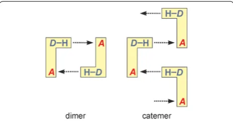
The dimer versus catemer competition (Fig. 1) in small carboxylic acids [2, 3] is an example for two HBSs which are based on identical D-H and A sites but differ in the multiplic-ity of their H-bond connections (two-point vs. one-point). The stabilisation contribution from a molecule–molecule
Open Access
interaction involving two H-bonds exceeds that from each of two alternative one-point interactions significantly. Poly-morphs differing in the multiplicity of their H-bond con-nections therefore also differ substantially in the relative distribution of energy contributions from individual mol-ecule–molecule interactions, whereas the lattice energy differences for polymorph pairs of small organic molecules are typically very small [4–6] (<2 kJ mol−1 for 50 % of pairs and >7.2 kJ mol−1 for only 5 % of pairs [7]). This means that compensation effects arising from the packing of multiple HBS instances may be critical for the competition between one-point and multiple-point HBSs. In order to gain a bet-ter understanding of the nature of this competition, the mol-ecule–molecule interactions in the corresponding crystals need to be examined in their entirety.
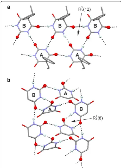
Aside from small carboxylic acids [2, 3, 8] and aromatic urea dicarboxylic acids [9], competing one-point/multi-ple-point H-bond motifs occur for example in uracils [10], carbamazepine and its analogues [11–14], compound DB7 [15], aripiprazole [16–18], sulfonamides [19–21] and in barbiturates [22–24]. The 5,5-disubstituted derivatives of barbituric acid display a rigid 2,4,6-pyrimidinetrione skel-eton whose two N–H and three carbonyl groups can serve as donor and acceptor sites, respectively, of N–H···O=C bonds. The rigid geometry of the 2,4,6-pyrimidinetrione fragment predetermines the geometries of intermolecu-lar N–H···O=C bonds (Fig. 2) within the ensuing 1-, 2- or 3-periodic HBSs (chains, layers and frameworks). As a result of these restrictions, only a limited number of experimental HBSs are found in this set of barbiturates [23] (see Table 1), and these HBSs are based on different combinations of one-point and two-point N–H···O= C-bond connections (o- and t-connections).
A prototypical barbiturate is phenobarbital [Pbtl, 5-ethyl-5-phenyl-2,4,6(1H, 3H, 5H)-pyrimidinetrione, Scheme 1] which is a sedative and anticonvulsant agent, applied as an anaesthetic and in the treatment of epi-lepsy and neonatal seizures. The polymorphism of Pbtl has been studied extensively [25–27] and eleven
polymorphic forms, denoted by I–XI, are known [28–
31]. Forms I–VI are relatively stable at ambient condi-tions. Their experimental order of stability at 20 °C is
I > II > III > IV > V/VI [26], and they can be produced by sublimation (I–VI) or crystallisation from solution (I–III;
IV only as an intermediate [32]) or from the melt (IV–
VI). Each of the modifications VII–XI can be obtained only in a melt film preparation and only in the presence of a specific second barbiturate as a structural template (“isomorphic seeding”) [25]. Crystal structure reports exist for I–III (Table 2) [26, 33, 34], several solvates [35] and a monohydrate [36] of Pbtl.
Herein we report single crystal structure determi-nations for forms IV and V. A structure model for polymorph X was derived from an isostructural co-crystal. The polymorphs I–V and X contain five dis-tinct N–H···O=C-bond motifs (or combinations of such motifs) with different quantitative proportions of o- and t-connections. Interaction energies associated with these HBSs were systematically compared using specific energy contributions of molecule–molecule interactions obtained from semi-classical density sums (SCDS-PIXEL) calculations [37–40]. An optimisation of molecular geometry was carried out and the intramo-lecular energy penalties of the experimental mointramo-lecular geometries were determined. Using the XPac method [41], the new crystal data for V, VI and X were compared to theoretical Pbtl structures from a previous study [42].
Results
Hydrogen‑bonded structures
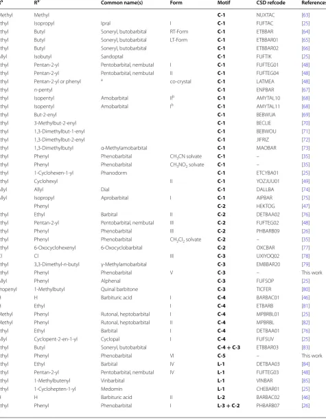
The Cambridge Structural Database (version 5.35) [43] and recent literature contain the 53 unique crystal struc-tures of barbituric acid and its 5-substituted derivatives listed in Table 1. These crystals have in common that each of the two N–H groups per molecule is engaged in a single intermolecular N–H···O=C interaction. The avail-ability of three carbonyl groups per molecule enables var-ious H-bond connectivity modes, whereas the inflexible arrangement of the D and A functionalities within the 2,4,6(1H,3H)-pyrimidinetrione unit predetermines the geometry of the resulting H-bonded structures. Alto-gether, 13 distinct H-bonded chain, layer or framework structures have been identified so far (Table 2), with one-dimensional structures, specifically the loop chains C-1
and C-2, dominating this set of barbiturates (Table 1). For the purpose of classification, one has to distinguish between the carbonyl group at C2 on the one hand and the two topologically equivalent carbonyl groups at C4 and C6 on the other (Fig. 2).1 The observed HBSs contain
1 The carbonyl group at C2 will be referred to as “C2 carbonyl group” and
any one of the two topologically equivalent carbonyl groups at C4 or C6 will be referred to as “C4/C6 carbonyl group”.
different quantitative proportions of o- and t-connec-tions, but as each NH donor function is employed exactly once, the condition
applies throughout, where No and Nt is the number of o- and t-connections, respectively. Each [No, Nt] com-bination of [0, 2], [4, 0] and [2, 1] is permitted for uni-nodal nets. The structures C-5 (form VI) and L-3 (forms
I and II) are both binodal, i.e. they feature two sets of topologically distinct molecules, whereas the layer
L-6 [23] contains three molecule types with distinct
(1) No+2Nt=4
H-bond connectivity modes. In these cases, condition (1) applies for No and Nt parameters averaged over the HBS (Table 2).
Molecules forming the loop chains C-1 and C-2 (Fig. 2) are linked by two antiparallel t-connections so that [No, Nt] = [0, 2]. The underlying topology of each of C-1 and
C-2 is that of a simple chain. In an alternative graph-set description according to Etter [44, 45], their “loops” represent R22(8) rings. The C-1 type (form X) contains two topologically distinct R22(8) rings in which either two O2 or two O4/6 sites are employed, whereas in a
Table 1 N–H···O=C bonded chain (C-1 to C-5), layer (L-1 to L-6) and framework (F-1, F-2) structures found in solid forms of barbituric acid and its 5-substituted derivatives
R5 R5′ Common name(s) Form Motif CSD refcode References
Methyl Methyl C-1 NUXTAC [63]
Ethyl Isopropyl Ipral I C-1 FUFTAC [25]
Ethyl Butyl Soneryl, butobarbital RT-Form C-1 ETBBAR [64]
Ethyl Butyl Soneryl, butobarbital LT-Form C-1 ETBBAR01 [65]
Ethyl Butyl Soneryl, butobarbital C-1 ETBBAR02 [66]
Allyl Isobutyl Sandoptal C-1 FUFTIK [25]
Ethyl Pentan-2-yl Pentobarbital, nembutal I C-1 FUFTEG01 [48]
Ethyl Pentan-2-yl Pentobarbital, nembutal II C-1 FUFTEG04 [48]
Ethyl Pentan-2-yl or phenyl a co-crystal C-1 LATMEA [48]
Ethyl n-pentyl C-1 ENPBAR [67]
Ethyl Isopentyl Amobarbital IIb C-1 AMYTAL10 [68]
Ethyl Isopentyl Amobarbital Ib C-1 AMYTAL11 [68]
Ethyl But-2-enyl C-1 BEBWUA [69]
Ethyl 3-Methylbut-2-enyl C-1 BECLIE [70]
Ethyl 1,3-Dimethylbut-1-enyl C-1 BEBWOU [71]
Ethyl 1,3-Dimethylbut-2-enyl C-1 JIFRIZ [72]
Ethyl 1,3-Dimethylbutyl α-Methylamobarbital C-1 MAOBAR [73]
Ethyl Phenyl Phenobarbital CH3CN solvate C-1 – [35]
Ethyl Phenyl Phenobarbital CH3NO2 solvate C-1 – [35]
Ethyl 1-Cyclohexen-1-yl Phanodorm C-1 ETCYBA01 [25]
Ethyl Cyclohexyl II C-1 YOZJUU01 [49]
Allyl Allyl Dial C-1 DALLBA [74]
Allyl Isopropyl Aprobarbital I C-1 AIPBAR [75]
F Phenyl C-2 HEKTOG [47]
Ethyl Ethyl Barbital II C-2 DETBAA02 [76]
Ethyl Pentan-2-yl Pentobarbital, nembutal III C-2 FUFTEG02 [48]
Ethyl Phenyl Phenobarbital III C-2 PHBARB09 [26]
Ethyl Phenyl Phenobarbital CH2Cl2 solvate C-2 – [35]
Ethyl 6-Oxocyclohexenyl 6-Oxocyclobarbital C-2 OXCBAR [77]
Cl Cl III C-3 UXIYOQ02 [78]
Ethyl 3,3-Dimethyl-n-butyl γ-Methylamobarbital C-3 EMBBAR20 [79]
Ethyl Phenyl Phenobarbital V C-3 – This work
Allyl Phenyl Alphenal C-3 FUFSOP [25]
Propenyl 1-Methylbutyl Quinal barbitone C-3 TICFER [80]
H H Barbituric acid I C-4 BARBAC01 [46]
H Ethyl I C-4 ETBARB [81]
Methyl Phenyl Rutonal, heptobarbital I C-4 MPBRBL01 [25]
Methyl Phenyl Rutonal, heptobarbital II C-4 MPBRBL [82]
Ethyl Ethyl Barbital I C-4 DETBAA01 [76]
Allyl Cyclopent-2-en-1-yl Cyclopal I C-4 FUFSUV [25]
Ethyl Butyl Soneryl, butobarbital C-4+C-3 ETBBAR03 [83]
Ethyl Phenyl Phenobarbital VI C-5 – This work
Ethyl Ethyl Barbital IV L-1 DETBAA03 [84]
Ethyl Pentan-2-yl Pentobarbital, nembutal IV L-1 FUFTEG03 [48]
Ethyl 1-Methylbutenyl Vinbarbital L-1 VINBAR [85]
Ethyl 1-Cyclohepten-1-yl Medomin L-1 CHEBAR01 [25]
H H Barbituric acid II L-2 BARBAC02 [46]
are employed, and all its R22(8) rings are topologically equivalent.
The molecules in a C-3 tape (form V) possess four o-connections so that [No, Nt] = [4, 0] (Fig. 2). Via C4/6 carbonyl groups, they form two parallel N–H···O=C bonded strands which are offset against one another by one half of a period along the translation vector. N–H···O=C bonding between the strands via C2 car-bonyl groups results in fused R33(12) rings. Four o-con-nections per molecule are also present in the layer structure L-2 [46] which has the topology of the (4,4) net and in the dia framework F-1 [47].
In an L-3 layer (forms I and II), molecules of type A are linked into C-2 chains and B-type molecules serve as N–H···O=C bonded bridges between these chains (Fig. 2). In molecule A, the H-bond acceptor functions of the carbonyl groups at C4 and C6 are each employed twice, whereas none of the carbonyl groups of molecule B is involved in hydrogen bonding. Each molecule A forms two t-connections to A molecules and o-connections to two B molecules. There are no H-bonds between B mol-ecules. The [No, Nt] parameters for molecules A and B are [2, 2] and [2, 0], respectively, and the overall [No, Nt] parameter combination for the L-3 layer is [2, 1].
The binodal tape C-5 (Fig. 2) is a novel structure found exclusively in the Pbtl polymorph VI. Molecules of type A are linked, by o-connections via C4 carbonyl groups, into two parallel strands. Additionally, the C4 and C2 carbonyl groups of molecules A and B, respectively, are employed in an asymmetrical and antiparallel t-connec-tion. Molecule A forms also an o-connection to a sec-ond B molecule via its C2 carbonyl group. There are no H-bonds between B molecules, which serve as H-bridges between two strands. The molecule types A and B have See Fig. 2 and Ref. [23] for graphical representations. R5 and R5′ are the substituents at ring position 5
a Co-crystal of phenobarbital and pentobarbital b Nomenclature according to Ref. [25]
Table 1 continued
R5 R5′ Common name(s) Form Motif CSD refcode References
Ethyl Phenyl Phenobarbital II L-3+C-2 PHBARB08 [26]
Ethyl Cyclohexyl I L-4 YOZJUU [49]
Isopropyl 2-Bromoallyl Noctal II L-4 UXIYIK [23]
Cl Cl I L-5 UXIYOQ [23]
Cl Cl II L-6 UXIYOQ01 [23]
Br Br I L-6 UXIZAD [23]
F F F-1 HEKTIA [47]
Br Br II F-2 UXIZAD01 [23]
Scheme 1 Structural formula of Pbtl
Table 2 Descriptors for HBS types found in barbiturates: short HBS symbol [19] and number of o- and t-connections [No, Nt]
For graphical representations, see Fig. 2 and Ref. [23]
Type Short HBS symbol [No, Nt] [No, Nt]A [No, Nt]B … Pbtl form(s)
C-1 C42[0] [0, 2] X
C-2 C42[0] [0, 2] I, II, III
C-3 C44[33.42.5] [4, 0] V
C-4 C43[42.6] [2, 1]
C-5 C54.32[(53.62.7)(5)] [2, 1] [3, 1][1, 1] VI
L-1 L43[63-hcb] [2, 1]
L-2 L44[44.62-sql] [4, 0]
L-3 L64.22[(64.8.10)(6)] [2, 1] [2, 2][2, 0] I, II
L-4 L43[63-hcb] [2, 1]
L-5 L43[63-hcb] [2, 1]
L-6 L32.54.43[(10)
(63.103)(63)] [2, 1] [1, 1][3, 1][2, 1]
F-1 F44[66-dia] [4, 0]
the parameters [No, Nt]A = [3, 1] and [No, Nt]B = [1, 1] and the overall [No, Nt] combination for the C-5 tape is [2, 1]. Five uninodal HBSs with [No, Nt] = [2, 1] are known, namely the C-4 ladder, three distinct layer struc-tures (L-1, L-4, L-5), each having the topology of the (6,3) net, and the ths framework F-2 [23]. The connectiv-ity and topology characteristics of the barbiturate HBSs are listed in Table 2 and an illustration of the variations in No and Nt is given in Fig. 3.
SCDS‑PIXEL calculations
Total PIXEL energies of individual molecule–molecule interactions (ET) can be divided into contributions from Coulombic (EC), polarisation (EP), dispersion (ED) and repulsion (ER) terms. The polarisation energy is not pair-wise additive (many-body effect) so that the total PIXEL energy for the crystal, ET,Cry, differs slightly from the sum of all individual PIXEL interaction energies ET,Σ. For the Pbtl polymorphs, this difference is 2–3 kJ mol−1 (<2.5 % of ET,Cry; see Table 3).
Various aspects of the PIXEL calculation for each poly-morph will be visualised in a special kind of diagram whose data points represent molecule–molecule inter-actions energies accounting for at least 95 % of ET,Cry, with internal HBS interactions separated from con-tacts between different instances of the HBS (labelled
@1, @2,…). Moreover, sums of PIXEL energies will be compared in order to assess relative contributions from
certain groups of interactions. The molecule–molecule interactions in each crystal structure will be ranked in descending order of their stability contributions (#1, #2, #3…), with symmetry equivalence indicated by a prime (e.g. #1/1′).
Polymorphs containing exclusively or predominantly t-connections, i.e. X (C-1), III (C-2), I and II (C-2 + L-3), will be discussed first, followed by forms V (C-3) and VI
(C-5). PIXEL energies do not account for differences in molecular conformation, and this topic will be discussed in a separate section. Detailed results of SCDS-PIXEL calculations are given in Additional file 1: Fig. S7 and Tables S1–S12.
HBS type C-1: polymorph X
The structure of polymorph X has not been determined from single crystal data. Melt film experiments [25] indi-cated it to be isostructural with the co-crystal of Pbtl with 5-ethyl-5-(pentan-2-yl)barbituric acid (pentobarbi-tal). The asymmetric unit of this co-crystal (space group C2/c) consists of a single barbiturate molecule whose R5′ substituent is disordered between the pentan-2-yl
and phenyl groups of the two chemical components [48]. An approximate structure model for polymorph X
was derived by removing the pentan-2-yl disorder frag-ment from the co-crystal structure (Additional file 1: Section 8).
The C-1 structure (Fig. 2) is defined by two independ-ent t-connections with very similar interaction energies (#1: −47.5 kJ mol−1; A: O4) and (#2: −47.2 kJ mol−1; A: O2), with a crystallographic two-fold axis pass-ing through the centre of the respective R22(8) ring. As expected, these interactions are dominated by the EC term and the C-1 tape contains no significant non-H-bonded interactions (Fig. 4a).
Each Pbtl molecule interacts with eight other mol-ecules belonging to four different C-1 chains, i.e. @1
(#3, #4, #9), @2 (#6/6′, #8), @3 (#5) and @4 (#9). Each of the eight interactions (PIXEL energies −19.7 to −12.1 kJ mol−1) is dominated by the E
D term (Additional file 1: Table S12). The chain–chain contact @1 involves the mutual interdigitation of phenyl groups (#3, #4) and contact @2 the interdigitation of ethyl groups (#6/6′) (Figs. 4b, 5). Internal C-1 interactions contribute 39 % to the ET,Cry value of −121.1 kJ mol−1, whilst @1 and @2 account for 21 and 18 %, respectively, of ET,Cry. A number of 2D and 3D packing relationships between barbiturates are based on the packing motif of the centrosymmetric chain pair @2 [25, 49].
Each of the molecule–molecule interactions #3, #5 and #8 involves a pair of symmetry-related C–H···O contacts (H···O = 2.51–2.68 Å and CHO = 140°–170° and a sig-nificant EC contribution (−9.1 to −9.8 kJ mol−1), which
is however still considerably lower than the respective ED contribution (−15.1 to −21.4 kJ mol−1). These C–H···O contacts are formed between the phenyl group (#3) or the CH2 group (#5) and the C4/6 carbonyl group not involved in classical H-bonds or between the methyl and the C2 carbonyl group (#8; for details, see Additional file 1: Table S12).
HBS type C-2: polymorph III
The structure of III (space group P21/c) contains one independent molecule. Its C-2 chain (Fig. 2) possesses 21 symmetry. The interaction energy of its t-connections (#1/1′) of −45.4 kJ mol−1 is similar to the correspond-ing values in X. The energies of the next four strong-est interactions (#3, #4, #5/5′) lie between −22.1 and −19.7 kJ mol−1 and each of them is dominated by the E
D term (Additional file 1: Table S7). They result mainly from the pairwise antiparallel alignment of ethyl-C5-phenyl
fragments in the case of #3 and from the pairwise stack-ing of ethyl groups with phenyl groups in the case of #5/5′. The relatively large EC term (−13.2 kJ mol−1) for interaction #4 coincides with the presence of two symmetry-related (phenyl)C–H···O=C contacts (H···O = 2.53 Å, CHO = 139°) involving the C2 car-bonyl group, which is not engaged in classical hydrogen bonding. However, the stabilisation contribution from ED (−17.3 kJ mol−1) is still higher than E
C for interaction #4. A similar (phenyl)C–H···O=C contact geometry (H···O 2.61 Å, CHO = 151°), also involving the C2 carbonyl group, is associated with interaction #10/10′, but here the EC contribution is just −5.5 kJ mol−1.
The two internal C-2 interactions account for approxi-mately 38 % of ET,Cry of −118.3 kJ mol−1, and the inter-actions with molecules belonging to four neighbouring chains @1 (2 pairwise interactions), @2 (2), @3 (2) and
@4 (3) account for 17, 13, 12 and 11 %, respectively, of
Table 3 Crystal data and PIXEL energies of polymorphs of Pbtl
a The matrix (100001101) transforms the room temperature data reported by Williams [36] (a = 12.66, b = 6.75, c = 27.69 Å; β = 106.9°; P21/c) into a unit cell
(a′ = 12.66, b′ = 6.75, c′ = 26.89 Å; β’ = 99.9°; P21/n) which matches our data
b The structure model for form X (Additional file 1: Section 8) was derived from the isostructural co-crystal of Pbtl with pentobarbital (the quoted CCDC refcode, unit
cell data and Texp all refer to the co-crystal) c E
T,Cry not determined because of Z′ > 2 d Not applicable
e Exists only in a melt-film preparation and in the presence of a structurally analogous second barbiturate f Based on the results of SCDS-PIXEL calculations, corrected for ΔE
intra
Form I II III Va VI Xb
References [26] [26] [26] This work This work [25, 48]
CCDC refcode PHBARB07 PHBARB08 PHBARB09 – – LATMEA
Space group P21/n P1 P21/c P21/n P21/n C2/c
Z′ 3 3 1 2 2 1
a (Å) 10.70 10.74 9.55 12.76 14.67 12.67
b (Å) 47.26 23.40 11.85 6.76 6.90 20.69
c (Å) 6.80 6.72 10.81 26.85 23.03 10.25
α (°) 90 91.0 90 90 90 90
β (°) 94.2 94.5 111.6 98.8 94.1 118.5
γ (°) 90 88.4 90 90 90 90
Texp (K) 298 173 298 173 173 173
D (g cm−3) 1.349 1.376 1.357 1.348 1.327 d
HBS C-2+L-3 C-2+L-3 C-2 C-3 C-5 C-1
[No, Nt] [4/3, 4/3] [4/3, 4/3] [0, 2] [4, 0] [2, 1] [0, 2]
m.p. (°C) [26] 176 174 168 160 156 126
ET,Cry/ΔEintra (kJ mol−1) c/7.3 c/7.5 −118.3/3.9 −122.4/13.1 −114.9/3.7 −118.3/8.0
ET,Σ (kJ mol−1) −123.3 −122.4 −120.5 −124.1 −117.9 −121.1
ET,Σ(A)/ΔEintra (kJ mol−1) −143.1/8.9 −141.4/8.7 – −120.9/8.5 −128.3/0.3 –
ET,Σ(B)/ΔEintra (kJ mol−1) −103.8/6.9 −104.0/8.2 – −127.4/17.6 −107.5/7.1 –
ET,Σ(C)/ΔEintra (kJ mol−1) −122.9/6.0 −121.9/5.5 – – – –
Density order 3rd 1st 2nd 4th 5th d
Stability order (RT) [26] 1st 2nd 3rd 4/5th 4/5th e
ET,Cry (Figs. 6, 7). This situation differs somewhat from the packing of C-1 chains in X which is dominated by just two chain–chain interactions (@1, @2) which con-tribute 40 % of ET,Cry.
HBS types L-3 + C-2: polymorph I
The crystal structure of form I (space group P21/c) con-tains three independent molecules, labelled A–C. A and B molecules are linked into an L-3 layer (Fig. 2). This layer consists of C-2 chains, formed exclusively by A mol-ecules, and bridging B molecules. The L-3 structures lie parallel to (010) and alternate with stacks of C-2 chains composed of C molecules (Additional file 1: Fig. S4). The two distinct C-2 chains formed by A and C molecules differ in that the former (as part of a L-3 layer) possess
glide symmetry, whereas the latter contain inversion cen-tres (Additional file 1: Fig. S5).
The energy associated with the centrosymmetric t-interaction between A molecules is −49.2 kJ mol−1 (#2/2′) and energies of −40.5 and −34.0 kJ mol−1 (5/5′ and 7/7′) are calculated for the o-interactions between A and B molecules (Fig. 8). Within an L-3 layer, the strong-est non-H-bonded AA interactions of −17.2 kJ mol−1 (#10/10′), between neighbouring C-2 subunits (related by a [001] translation), and the strongest BB interactions of −15.5 kJ mol−1 (#14/14′) each involve relatively large E
D contributions. There are another eight intra-L-3 contacts with energies between −11.1 and −8.4 kJ mol−1. The energies for the t-connections of the C-2 chain of mol-ecule C, −49.7 and −48.1 kJ mol−1, are very similar to the corresponding values for the C-2 chains formed by A molecules and in polymorph III.
Internal H-bond and non-H-bond interactions of the
L-3 layer account for 54 % and internal C-2 chain inter-actions of C molecules account for 13 % of ET,Σ. Contacts between L-3 layers (molecules A + B) and C-2 stacks (molecule C) contribute 19 % to ET,Σ (@1), and the con-tacts @2 and @3 between neighbouring C-2 chains con-tribute 5 and 4 %, respectively (Figs. 8, 9). Due to their fundamentally different environments and different
Fig. 5 Packing diagram of polymorph X, showing interactions of a selected Pbtl molecule (drawn in ball-and-sticks-style) within the same C-1 chain (blue) and with molecules belonging to three neigh-bouring chains (@1–@3; see Fig. 4). Together, hydrogen bonding and the …@1@2@1@2… stacking of chain pairs account for 78 % of
ET,Cry
Fig. 4 Results of SCDS-PIXEL calculations for polymorph X. a Interac-tion energies, represented by balls, are separated into internal C-1 interactions (blue) and chain–chain contacts (highlighted@1, red; @2, orange; @3, green). The horizontal bars indicate cumulative PIXEL energies (summation from left to right) relative to ET,Cry (scale on the
involvement in N–H···O=C bonds, the three independ-ent molecules also differ substantially in their PIXEL energy sums: 143.1 kJ mol−1 (A), −103.8 kJ mol−1 (B) and −122.9 kJ mol−1 (C).
HBS types L-3 + C-2: polymorph II
Polymorph II (space group P 1) is a Z′ = 3 structure
whose molecules A and B are linked into an L-3 layer, whilst C-type molecules form a C-2 chain, and it exhib-its a very close 2D packing similarity with polymorph I
[26]. In fact, the only fundamental difference between these two modifications is the symmetry of the C-2 chain formed by the respective A-type molecules (I: glide sym-metry, II: inversion; see Additional file 1: Fig. S4).
The comparison of interaction energy diagrams (Addi-tional file 1: Fig. S7; see also Tables S1–S6) shows that this packing similarity results in a striking similarity of corresponding pairwise interaction energies. Therefore, the general assessment of relative energy contributions attributable to L-3 and C-2 units and to their packing in polymorph I (previous section) is also valid for poly-morph II.
HBS type C-3: polymorph V
Williams [36] reported space group and unit cell data for polymorph V which indicated a crystal structure with two independent molecules, and these data are consist-ent, after unit cell transformation, with those of the full crystal structure analysis carried out by us (see footnote a of Table 3). Form V has the space group symmetry P21/c and contains two independent molecules, labelled A and B. It contains N–H···O=C bonded C-3 tapes (Fig. 10) which are arranged parallel to [010].
Each molecule forms o-connections to four neighbour-ing molecules. A and B molecules are linked into sepa-rate H-bonded strands with translation symmetry, which are offset against one another by one half of a transla-tion period. The linkage between the two parallel strands via N–H···O=C bonds results in fused R33(12) rings. Although A and B molecules are crystallographically dis-tinct, they are topologically equivalent in the context of the (uninodal) C-3 structure.
Fig. 6 Results of SCDS-PIXEL calculations for polymorph III. a Interac-tion energies, represented by balls, are separated into internal C-2 interactions (blue) and chain–chain interactions (highlighted@1, red; @2, orange; @3, green). The horizontal bars indicate cumulative PIXEL energies (summation from left to right) relative to the ET,Cry (scale on the right-hand side). b The six most important pairwise interactions involving a central molecule (orange). The mean plane of the pyrimi-dine ring of the central molecule is drawn, H atoms are omitted for clarity and H-bonds are indicated by blue lines
Interaction energies of −32.9 kJ mol−1 were obtained both for the o-interactions between A-type mole-cules (#1/1′) and the analogous interactions between
B-molecules (#2/2′). Considerably lower stabilisation effects of −23.8 and −23.2 kJ mol−1 result from the o-interactions (#5/5′ and #10/10′) between A and B Fig. 8 Results of SCDS-PIXEL calculations for polymorph I. a Interaction energies, represented by balls, are separated into internal L-3 (blue) interac-tions, internal C-2 (red) interactions, interactions between a L-3 layer and a stack of C-2 chains (@1, orange) and interactions between neighbouring C-2 (@2, green; @3, beige). The horizontal bars indicate cumulative PIXEL energies (summation from left to right) relative to the ET,Cry (scale on the
strands, which is the result of higher (by 9.9–6.4 kJ mol−1) dispersion terms. Two H-bonded molecules belonging to different strands have fewer van der Waals interactions with one another than two H-bonded molecules within the same strand (Fig. 11b, c). Moreover, the PIXEL ener-gies of the o-connections #5/5′ and #10/10′ are very similar to those of seven non-H-bond interactions (#7, #8/8′, #12/12′, #14/14′; −23.5 to −20.9 kJ mol−1). Each of the latter involves extensive van der Waals contacts (ED = −21.9 to −30.7 kJ mol−1) which compensate for the lower EC contribution in the absence of any N–H···O=C bonding (Additional file 1: Tables S8 and S9). The inter-actions #12/12′ contain a single contact (mol. B)(CH2) C–H···O(mol. A) in which the C2 carbonyl group of mol-ecule A is engaged (H···O 2.58 Å, CHO = 143°), but the associated Coulombic contribution (−11.7 kJ mol−1) is less stabilising than ED (−28.4 kJ mol−1).
The sum of all pairwise interaction energies involving molecule A is 6.5 kJ mol−1 higher than the correspond-ing sum for molecule B. This reflects somewhat different packing environments which are associated with differ-ent molecular conformations (see below). Internal C-3
interactions account for 46 % of ET,Cry. The C-3 tapes are arranged in centrosymmetric pairs (@2, see Fig. 12) in such a way that the pyrimidine rings of the two tapes are somewhat offset against one another, the ethyl groups are oriented towards the centre of the centrosymmetric unit and the phenyl rings are oriented in the opposite direc-tion. Other centrosymmetric pairs of C-3 chains result in the mutual antiparallel interdigitation of sets of phenyl groups (@1, @3). The chain–chain interactions involve
Fig. 9 Packing diagram of polymorph I. One selected molecule of each type of A, B and C is drawn in ball-and-sticks-style. Together the internal L-3 (blue) and C-3 (orange) interactions account for 67 % of ET,Σ. Interactions between L-3 and C-3 chains (@1) account for 19 % and interactions between neighbouring C-3 chains (@2, @3) for 9 % of ET,Σ
either three (@1) or two (@2 and @3) of the most sta-bilising non-H-bond interactions mentioned above (see Fig. 11a). The chain–chain interactions @1, @2 and
@3 account for 21, 16 and 9 %, respectively, of ET,Cry. This means that 84 % of the stabilisation of the lattice is derived from columnar stacks of C-3 tapes parallel to [001] which involve the interactions @1 and @2 (Fig. 12).
HBS type C-5: polymorph VI
Polymorph VI has the space group symmetry P21/n and contains two independent molecules, labelled A and B. It contains the novel N–H···O=C bonded tape structure
C-5 (see Fig. 2) which possesses 21 symmetry. The two molecule types differ in their H-bond connectivity. Each A molecule forms three o-connections (to two A mol-ecules and one B molecule) and one t-connection (to a second B molecule). Each B molecule forms one o- and one t-connection to A-type molecules (Fig. 10b).
The presence of two parallel strands of H-bonded molecules is reminiscent of the C-3 tape. The C-5
type displays an unusual asymmetric R22(8) ring due to
N–H···O=C bonds involving the C2 carbonyl function of molecule B and the C4 carbonyl function of mol-ecule A. The energy contribution of −46.5 kJ mol−1
Fig. 12 Crystal packing of polymorph V. Interactions of selected A and B molecules (drawn in ball-and-sticks-style) within the same C-3 chain (blue) and with molecules belonging to four neighbouring chains (@1–@4; see Fig. 11). Together, C-3 hydrogen bonding and the @1 and @2 chain stacking interactions account for 84 % of ET,Cry
Fig. 11 Results of SCDS-PIXEL calculations for polymorph V. a Interaction energies, represented by balls, are separated into internal C-3 interactions (blue) and interactions between neighbouring C-3 tapes (highlighted@1, red; @2, orange; @3, green). The horizontal bars
associated with this asymmetric t-connection (#1/1′) is very similar to the corresponding values obtained for the symmetric t-connections in forms I, II, III and
X. The PIXEL energy calculated for the o-connections between A molecules which are related by a translation along [010] (#3/3′; −34.4 kJ mol−1) is similar to energies obtained for the analogous interactions in polymorph V
(#1/1′, #3/3′). The interaction energy for the second set of o-connections (#5/5′) in the C-5 tape is somewhat higher, −28.4 kJ mol−1. In addition to the two o- and four t-connections, the C-5 tape contains six non-H-bond
interactions with PIXEL energies between −13.9 and −8.3 kJ mol−1. Altogether, the internal interactions of the
C-5 tape account for 63 % of ET,Cry.
The six strongest external interactions (#7, #8/8′, #12/12′, #18; −19.2 to −12.1 kJ mol−1) all involve mol-ecules which belong to a single neighbouring C-5 tape (@1; see Figs. 13a, 14). Each of these molecule–molecule interactions is dominated by the ED term as a result of extensive van der Waals contacts, mainly between phenyl groups. In the structure of polymorph VI, each instance of C-5 is surrounded by six other C-5 tapes (three sym-metrical interaction pairs, @1, @2, @3; Fig. 14). The chain–chain interaction @1 defines, together with the internal C-5 interactions, the packing within
101 planes which accounts for 85 % of ET,Cry and @1 alone accounts for 21 %. Interactions @2 (six molecule–molecule con-tacts) and @3 (two molecule–molecule contacts) account for approximately 10 and 5 %, respectively, of the stabili-sation energy.
Molecular geometry
The PIXEL energy (ET,Cry) is an intermolecular energy derived by integration over the isolated molecule charge densities placed in the crystal structure. The electrostatic contribution (EC,Cry) is rigorously derived by this proce-dure and various approximations are used to estimate the polarisation (induction; EP,Cry), dispersion (ED,Cry) and repulsion (ER,Cry) contributions to the intermolecu-lar lattice energy. To make the PIXEL crystal energies of different Pbtl polymorphs comparable with one another, we have estimated the intramolecular energy penalties (∆Eintra) of their experimental conformations (Additional file 1: Table S13) with respect to the global conforma-tional energy minimum. The obtained ∆Eintra values were then added to the PIXEL energy ET,Cry.
The geometry of a Pbtl molecule can be characterised by two parameters, the torsion angle ф describing the ethyl rotation and the twist angle ω between the phenyl and pyrimidine rings [42] (Fig. 15a). The ф values for all previously reported experimental conformations lie within the narrow range of 0° ± 5°, indicating that the ethyl orientation perpendicular to the pyrimidinetrione ring might be the preferred one in the solid state of Pbtl. At the same time there is a wide variation in the corre-sponding ω angles from 0° to 75°, which is in agreement with the free rotability of the phenyl group as derived from energy scans for an isolated molecule in the gas phase.
Like all the previously reported Pbtl forms, the confor-mations of molecule A of polymorph V, (ф, ω) = (−3°, 31°) and both independent Pbtl molecules of polymorph
VI, A: (ф, ω) = (−1°, 77°) and B: (ф, ω) = (1°, 42°) are located in the global energy minimum ‘valley’ (Fig. 15b). Fig. 13 Results of SCDS-PIXEL calculations for polymorph VI. a
The geometry of molecule B of V, (ф, ω) = (−129°, 31°), is unique in that it can be assigned to the second (local) energy minimum rather than the global energy mini-mum. A conformational change from the conformer of molecule B to that of molecule A would involve a rotation of the ethyl group (ф) by approximately 120° and require approximately 20 kJ mol−1. The fact that modification V was obtained only from the melt or by sublimation, but never from solution crystallisation experiments, may indicate that a conformation related to the global energy minimum ‘valley’ is preferred in solution.
Comparison of IV, V and X with previous crystal structure predictions
Pbtl was used by Day et al. [42] as a model flexible mol-ecule in a structure prediction study. 72 structures within 5 kJ mol−1 of the global minimum were identified as pos-sible candidates for new polymorphs (in addition to the previously published forms I–III). Six additional Z′ = 2 candidate structures for polymorph V were proposed because they matched the original space group sym-metry P21/c and the reduced cell (a = 12.66, b = 6.75, c = 26.89 Å; β = 99.9°) of Williams’ [36] original cell (a = 12.66, b = 6.75, c = 27.69 Å; β = 106.9°). However, we note that the
100010101
transformation involved in
this unit cell reduction implies a simultaneous transfor-mation of the space group symmetry from P21/c to P21/n. Using the program XPac [41, 50], we have compared the new structure models for polymorphs V, VI and X with the 78 theoretical Pbtl structures proposed by Day et al. [42].
There is no complete 3D match for the experimental structure of V, but one of the Z′ = 2 candidates for form
V (#6) with an energy difference from the global mini-mum of 7.71 kJ mol−1 (see Table 2 of Ref. [42]) displays certain features which are reminiscent of the experi-mental structure of V (Additional file 1: Fig. S8). Both structures contain centrosymmetric pairs of C-3 chains (propagating along [010]) which are arranged into stacks along the a-axis in such a way that phenyl groups belong-ing to neighbourbelong-ing chain pairs interdigitate (Fig. 16). However, they differ fundamentally in the packing mode Fig. 14 Crystal packing of polymorph VI. Interactions of selected A
and B molecules (drawn in ball-and-sticks-style) within the same C-5 chain (blue) and with molecules belonging to three neighbouring chains (@1–@3; see Fig. 13). Together, C-5 hydrogen bonding and @1 chain stacking account for 84 % of ET,Cry
between adjacent stacks of H-bonded chains. The molec-ular conformations (ф, ω) = (1°, −21°) and (5°, 23°) for this theoretical structure are both well within the “valley” of low-energy conformations close to ф = 0°, whereas in the experimental structure one molecule shows an atypi-cal ethyl rotation with ф = −129° (see Fig. 15).
No close match was found for form VI, and it seems that its unique C-5 chain does not occur in any of the theoretical structures. However, there is a very close 3D match between the derived structure model for poly-morph X (Table 3) and a theoretical structure (#72; reported in I2/a; transformed C2/c unit cell: a = 12.91 Å, b = 20.26 Å, c = 10.34 Å; β = 115.3°). An XPac
comparison based on geometrical parameters derived from complete sets of non-H atoms gives a low dissimi-larity index, x = 5.2 (see Additional file 1: Fig. S9).
Discussion
The PIXEL energies for all symmetrical (C-1, C-2, L-3) and asymmetrical (C-5) t-connections in Pbtl poly-morphs lie between −45.4 and −49.2 kJ mol−1 (Table 4). The reason for this relatively narrow range is that the rigid R22(8) ring geometry permits only small variations in van der Waals interactions and therefore dispersion con-tributions. The geometry of an o-connection is much less constrained than that of a t-connection, and the corre-sponding PIXEL energies (−23.1 to −40.5 kJ mol−1) can therefore vary by a wide margin. For example, the stabi-lisation contribution from the strongest o-connection encountered in this study (#5/5′ in the L-3 layer of I) is 5 kJ mol−1 lower than that from the weakest t-connection (#1/1′ in the C-2 chain of III), whereas the four weakest o-interactions in the C-3 chain of V (#5/5′, #10/10′) are only just as stabilising as the three strongest non-H-bond interactions in the same crystal structure (#7, #8/8′) (see Fig. 11a). The implied compensation effect arises from a large variation in the dispersion term (e.g. #10/10′: ED = −9.5 kJ mol−1 vs. #7: ED = −30.7 kJ mol−1). The observation that enhanced dispersion contributions can fully compensate for the absence of classical H-bonding contradicts the conventional view that H-bonds always dominate the interaction hierarchy but is consistent with recent analyses of chiral carboxylic acids [8] and primary amines [51].
The (internal) molecule–molecule interactions within an HBS can be classified as being either H-bonded (via an o- or t-connection) or non-H-bonded. The latter type is relevant for the complex C-5 tape and L-3 layer structures where it accounts for a PIXEL energy sum of −17 kJ mol−1 (VI) and approximately −39 kJ mol−1 (I,
II), respectively. The first coordination shell of a molecule is of limited size and usually comprises no more than 14 significant interactions with other molecules. Therefore, the total number NHBS of internal (H-bond or non-H-bond) of a central molecule is an important characteristic of an HBS.
The average internal energy contribution (EHBS,Σ) from a C-1 or C-2 loop chain (NHBS = 2) is −47 kJ mol−1. The analogous PIXEL energy sums for the competing C-3
(NHBS = 4), C-5 (NHBS = 6) and L-3 (NHBS = 9) structures are ≈9, ≈25 and ≈52 kJ mol−1, respectively, lower than this C-1/C-2 value. Hence, HBSs containing exclusively t-connections result in the lowest and complex tape or layer structures result in the highest internal stabilisation contributions (Table 4). However, its lower NHBS number means that the first coordination shell of a t-connected Fig. 16 a Crystal structure of form V of Pbtl (space group P21/n) and
b the closest predicted structure for form V (space group setting
P21/c) from Ref. [42]. Each structure is viewed along the b-axis, the
molecule offers more accessible molecule sites for exter-nal interactions than that of an o-connected molecule. Specifically, a molecule in a C-1 or C-2 chain can engage in two more significant external interactions with mol-ecules belonging to neighbouring chains than a molecule within a C-3 chain structure. These additional interac-tions should easily enable a compensation for the internal advantage of C-3 over C1/C-2 (≈9 kJ mol−1). Therefore, the comparison of EHBS,Σ and NHBS values suggests that an HBS with t-connections (C-1/C-2) should be inher-ently more favourable than any alternative HBS which is based solely on o-connections (C-3). In order for the lat-ter to be a viable competitor, it has to enable a set of sig-nificantly more favourable external (packing) interactions in comparison to the former.
To analyse the packing effects associated with differ-ent HBS types, sums of molecule–molecule interaction energies, corrected for ΔEintra, have been plotted in a dia-gram (Fig. 17). For each polymorph, a series of molecu-lar clusters was generated by sequentially adding the 14 most important molecule–molecule interactions (first coordination shell) in descending order of their contri-butions to the lattice energy. For Z′ > 1 structures (I, V,
VI), separate cluster series were generated for independ-ent molecules, whose energy sums were averaged. Each data point in Fig. 17 corresponds to a specific cluster size and represents the difference in energy sums between the indicated polymorph and form III. As mentioned above, HBSs dominated by t-connections (I–III, X) are favoured if only the strongest interactions are taken into account.
For all Pbtl polymorphs, the cluster of size 4 contains the complete set of H-bond interactions. Corrected PIXEL energy sums for these clusters in forms I, II (both Nt = 4/3) and III, X (both Nt = 2) lie within a 2.4 kJ mol−1 interval, whereas the corresponding value for poly-morph V (Nt = 0) exceeds that of form III by more than 12 kJ mol−1. The effects of packing multiple C-5 tapes in
form V and multiple C-2 chains in form III are such that for each of the next seven highest ranked interactions average PIXEL energies of −17 and −12 kJ mol−1, respec-tively, are obtained. This means that the initial “disadvan-tage” of V has disappeared completely at cluster size 9, and V even becomes slightly more favourable than III at cluster size 11. If all weak contributions are taken into account, III has an overall 5.5 kJ mol−1 advantage over V. The plot in Fig. 17 illustrates that HBSs based on multiple H-bond connections result in the highest initial stabilisa-tion of small clusters and that HBSs based on o-connec-tions may overcome their inherent “disadvantage” only if they possess superior crystal packing characteristics.
An HBS based on multiple-point connections is more compact and often also of lower dimensionality than an alternative which contains exclusively o-connections (e.g. dimer vs. catemer or C-1/C-2 vs. C-3). Therefore, a higher number of theoretical 3D packing options exist for a multiple-point HBS than for a one-point competitor so that it seems likely that more viable crystal packing arrangements would emerge for the former than for the latter. Moreover, compact entities with multiple-point connections may be more likely to exist prior to nuclea-tion and could therefore be kinetically favoured. The domination of the barbiturate set of crystal structures by
C-1 and C-2 chains (Table 1) could be interpreted in terms of a general preference for HBSs which are based on multiple-point connections.2
As discussed above, an interaction between two non-H bonded molecules which involves strong disper-sion effects can be as stabilising as an o-interaction with
2 The fact that only 12 of the theoretical low energy structures reported by
Day et al. [35] contain C-1 or C-2 chains may be due to modelling errors. We note also that 15 of the 72 predicted Pbtl structures contain one NH group which is not engaged in an intermolecular N−H∙∙∙O interaction, a characteristic not encountered in any relevant experimental crystal struc-tures of Pbtl analogues (Table 1).
Table 4 Sums of internal energies, EHBS,Σ (kJ mol−1), from N–H···O=C bonded structures in polymorphs of Pbtl and their origin from different types of interaction
Contributions arise from NHBS pairwise contacts, of which there are No one-point H-bond connections, NT two-point connections and Nn non-H-bond interactions
and ranges of interaction energies ET (kJ mol−1) for the o- and t-connections involved. En,Σ (kJ mol−1) is the sum of all significant (internal) non-H-bonded interaction
energies within an HBS (C-5 and L-3 only)
HBS Form NHBS [No, Nt, Nn] EHBS,Σ ET range (o) ET range (t) En,Σ
C-1 X 2 [0, 2, 0] −47.5 −47.2 to −47.7
C-2 III 2 [0, 2, 0] −45.4 −45.4
C-2 I (C) 2 [0, 2, 0] −48.9 −48.1 to −49.7
C-2 II (C) 2 [0, 2, 0] −46.9 −46.8 to −47.0
C-3 V 4 [4, 0, 0] −56.4 −23.1 to −32.9
C-5 VI 6 [2, 1, 3] −72.0 −28.4 to −34.4 −46.5 −17.3
L-3 I (A + B) 10 [2, 1, 7] −100.2 −34.0 to −40.5 −49.2 −38.4
a smaller dispersion contribution (polymorph V). The importance of dispersion interactions [51] is not usually recognised in crystal structure discussions, which tend to focus on the interpretation of intermolecular atom– atom distances (with reference to van der Waals radii and standard geometries), for example in terms of con-ventional or weak hydrogen bonds [52, 53]. The forma-tion of convenforma-tional N–H···O=C bonds in barbiturates is largely predictable (but not the exact characteristics of the resulting HBS). By contrast, short intermolecular C–H···O contacts [1], which usually involve a small but significant Coulombic contribution, occur in a rather irregular fashion (see footnotes for Additional file 1: Tables S1–S12). However, in each such case, the crystal contains at least one other molecule–molecule interac-tion with a lower or only slightly higher PIXEL energy which involves neither an N–H···O=C bond nor a short C–H···O contact. The size of associated EC terms (rela-tive to differences in ED between individual molecule– molecule interactions) as well as the irregularity of their occurrence suggest an opportunistic rather than sys-tematic formation of short C–H···O contacts in Pbtl
polymorphs as part of an effort to optimise the stability of the crystal.
The SCDS-PIXEL method allows the comparison of energy sums ET,Σ(A, B,…) of interactions originating from the crystallographically distinct molecule types (A, B,…) of a Z′ > 1 structure [54]. In the case of forms I and II, ET,Σ(A) is approximately 20 and 40 kJ mol−1 lower than ET,Σ(C) and ET,Σ(B), respectively (Table 3), which reflects the different involvement of the three independent mol-ecules in o- and t-connections, e.g. [No, Nt] = [2, 2] (A) or [2, 0] (B) or [0, 2] (C). This means for example that the interactions of molecule B contribute 27.5 % less to the PIXEL energy of the crystal than those of molecule A. A comparison with an overview compiled by Gavezzotti for Z′ = 2 structures (Fig. 7 in Ref. [54]) suggests that the differences in ET,Σ(A, B,…) found in Pbtl forms I and II are unusually large.
In order to demonstrate that the results of the PIXEL calculations presented above are both realistic and con-sistent, we have attempted to rank the Pbtl polymorphs according to their PIXEL energies and have compared the result with available experimental data. This ranking was based on PIXEL energy sums, ET,Σ (Table 3), rather than total PIXEL energies, ET,Cry, which are not possible to calculate for the Z′ = 3 polymorphs I and II. Due to the non-additive character of the polarisation contribu-tion, the ET,Σ value obtained for each of III, V, VI and
X is between 1.7 and 3.0 kJ mol−1 lower than the cor-responding ET,Cry value. In order to make the PIXEL crystal energies of all Pbtl forms comparable to one another, experimental molecular conformations (Addi-tional file 1: Table S13) were estimated with respect to the global conformational energy minimum, individual ΔEintra values were calculated (Table 3) and added to ET,Cry. The stability order implied by this procedure is
III > I > II > VI > X > V, where the first three forms differ by just 1.7 kJ mol−1. This result is in good overall agree-ment with the findings of a previous experiagree-mental study (see Table 3) [26]. Low-temperature (173 K; II, V, VI,
X) as well as room-temperature (I, III) structure mod-els were used for our PIXEL calculations. On the basis of a previous report [55] describing two separate PIXEL calculations performed with a room-temperature and a low-temperature structure model of olanzapine, we esti-mate that the ET,Σ values quoted for I and III in Table 3 should be corrected by approximately −2 % to adjust for different temperatures. Moreover, an optimisation of the model for X (derived from the disordered co-crys-tal structure) would probably have resulted in a slightly lower ET,Σ.
The ΔEintra contributions of the experimental confor-mations located in the global energy minimum ‘valley’ were estimated to lie within a range of 0.3–8.9 kJ mol−1
Fig. 17 Differences between sums of PIXEL energies, corrected for ΔEintra, for molecule clusters in polymorphs I, II, V, VI and X in comparison to the corresponding energy sums calculated for polymorph III of Pbtl. For each polymorph, clusters were generated by sequentially adding the 14 most important pairwise energies, ranked in the order of their contribution to the lattice energy from highest to lowest. For each Pbtl polymorph, a broken horizontal line
indicates the difference to the corrected ET,Σ value of polymorph III, i.e. (ET,Σ+ ΔEintra)Pbtlpolymorph− (E
from the global minimum, with only molecule B of modi-fication V adopting a distinct high-energy conformation (17.6 kJ mol−1). This higher ΔE
intra penalty is compen-sated for by more stable intermolecular interactions.
Conclusions
There cannot be a straightforward answer to the ques-tion whether, for a given group of compounds, an HBS based on multiple-point connections should generally be more favourable than an alternative HBS contain-ing one-point connections (“dimer or catemer?”). Beside geometry restraints and factors such as accessibility and relative strength of H-bond donor and acceptor functions, the competition between alternative HBSs is governed by an interplay between internal energy contributions (from H-bond and non-H-bond molecule–molecule interac-tions) and stabilisation effects arising from the packing of multiple HBS instances. An HBS based on multiple-point H-bond connections (i.e. a dimer or a C-1 chain) possesses a more compact architecture than a one-point alternative (i.e. a catemer or a C-3 tape) and offers a higher number of packing alternatives, which may ultimately result in a higher number of potentially viable low-energy struc-tures. The observation that 60 % of the experimental crystal structures of barbiturates listed in Table 1 contain HBSs which are based exclusively on t-connections may be interpreted in this regard. However, the importance of (external) HBS packing characteristics implies that the competition situation between alternative HBSs can be critically affected by relatively small differences in molecu-lar geometry, for example by the size of the C5 ring sub-stituents in the case of the aforementioned barbiturates.
Experimental Materials
The Pbtl sample used in this study was purchased from Mallinckrodt Chemical Works (U.S.P. XIII Powder, USA) and consisted of a mixture of forms I and II.
Preparation of forms V and VI
Fine needles of V were obtained, together with crystals of II and III from sublimation experiments carried out on a Kofler hot bench, using a setup of two glass slides separated by a 1 cm spacer ring and a sublimation tem-perature of 135 °C (Additional file 1: Fig. S1). Single crys-tals of V, stored at 5 °C, were stable for at least 2 months, whereas a melt film of form V was previously reported to have transformed into either II or III within hours [26].
Polymorph VI was produced, on a hot bench, by the melting and partial dissolution of Pbtl powder immersed in paraffin oil and subsequent crystallisation at 100° C. Prismatic single crystals and spherical polycrystalline aggregates of VI were obtained (Additional file 1: Fig. S1).
The identity of the obtained crystals with the Pbtl poly-morphs V and VI was established by comparison of their IR spectra with reference data recorded in a previous study [26] (Additional file 1: Fig. S6).
Single‑crystal X‑ray structure analysis3
Intensity data were collected, using Cu radiation (V) or Mo radiation (VI), on an Oxford Diffraction Gemini-R Ultra dif-fractometer operated by the CrysAlis software [56]. The data were corrected for absorption effects by means of compari-son of equivalent reflections using the program SADABS [57]. The structures were solved using the direct methods procedure in SHELXS97 and refined by full-matrix least squares on F2 using SHELXL97 [58]. Non-hydrogen atoms were refined anisotropically. Hydrogen atoms were located in difference maps and those bonded to carbon atoms were fixed in idealised positions. NH hydrogen atoms were refined with a distance restraint of N–H = 0.88(2) Å. In the case of V, the displacement parameters of H atoms were set to 1.2Ueq (for NH, CH and CH2) or 1.5Ueq (for the CH3 group) of the parent N or C atom. In the case of VI, these parameters were refined freely. The molecular structures are shown in Additional file 1: Figs. S2 and S3 and the geomet-ric parameters of hydrogen bonds are listed in Table 5. The crystal structure data of polymorphs V (CCDC 1035977) and VI (CCDC 103598) have been deposited with Cam-bridge Crystallographic Data Centre.
Calculation of specific energy contributions
Intermolecular interaction energies were calculated with the semi-classical density sums (SCDS-PIXEL) [37–40] method using the program OPiX [59]. Details of these calculations are available in section 5 of Additional file 1. The structure models listed in Table 3 were used, and C–H and N–H distances were re-calculated to standard lengths within OPiX. No optimisation of the molecular geometry was performed. An electron density map was calculated on a three-dimensional grid with a step size of 0.08 Å at the MP2/6-31G(d,p) level using Gaussian 09 [60]. A PIXEL condensation factor of 3 was applied, giving superpixels with dimensions 0.24 × 0.24 × 0.24 Å3. The
3 Crystal data for form V: C
12H12N2O3, M = 232.24, monoclinic, a = 12.7606(12) Å, b = 6.7624(5) Å, c = 26.847(3) Å, β = 98.829(9)°, V = 2289.2(4) Å3, T = 173(2) K, space group P2
1/n, Z= 8, 7565 reflections measured, 3822 independent reflections (Rint = 0.1439); 3.3° ≤ θ ≤ 65.0°
(λ = 1.5418 Å). The final R1 value was 0.0718 (I > 2σ(I)). The final wR(F2)
values were 0.1310 (I > 2σ(I)) and 0.1775 (all data). The max. and min. residual densities were 0.23 and −0.22 e Å−3, respectively. Crystal data for form VI: C12H12N2O3, M = 232.24, monoclinic, a = 14.6701(11) Å, b = 6.9000(5) Å, c = 23.0308(19) Å, β = 94.072(7)°, V = 2325.4(3) Å3, T = 173(2) K, space group P21/n, Z = 8, 9105 reflections measured, 4104 independent reflections (Rint = 0.0499); 3.1° ≤ θ ≤ 25.1° (λ = 0.71073 Å).
The final R1 value was 0.0458 (I > 2σ (I)) and the final wR(F2) values were
![Fig. 2 Schematic representation according to Ref. [23] of selected N–H···O=C bonded chain and layer HBSs found in derivatives of barbituric acid](https://thumb-us.123doks.com/thumbv2/123dok_us/404649.2037831/3.595.58.539.89.522/schematic-representation-according-selected-bonded-chain-derivatives-barbituric.webp)
![Table 2 Descriptors for HBS types found in barbiturates: short HBS symbol [19] and number of o- and t-connections](https://thumb-us.123doks.com/thumbv2/123dok_us/404649.2037831/5.595.56.291.283.404/table-descriptors-types-barbiturates-short-symbol-number-connections.webp)
![Fig. 3 The parameters [No, Nt] for the HBS types formed by bar-biturates and for two combinations of HBS types (L-3 + C-2 and C-3 + C-4)](https://thumb-us.123doks.com/thumbv2/123dok_us/404649.2037831/6.595.57.290.449.680/fig-parameters-hbs-types-formed-biturates-combinations-types.webp)