Vol.9 (2019) No. 1
ISSN: 2088-5334
Co-existence Issue in IoT Deployment using Heterogeneous Wireless
Network (HetNet): Interference Mitigation using Cognitive Radio
Ayaskanta Mishra
**School of Electronics Engineering, Kalinga Institute of Industrial Technology (KIIT) Deemed to be University, Bhubaneswar, 751024, India E-mail: [email protected]
Abstract—In today’s era of Machine-to-Machine (M2M) communication, where a tiny embedded device is having enough functionality and computational power to be network enabled for various applications aided with sensors, relays, and actuators to make Internet-of-Things (IoT) a reality. IoT is not a technology by itself rather a vision to interconnect every single piece of intelligent electronics using existing LAYER-I and II data communication standards and the internet based on OSI Layer Architecture. In the context of deployment of such IoT networks, it is imperative; a heterogeneous wireless network will be most viable for the need of different application-specific scenarios. The primary goal of this paper is to propose a Cognitive Radio (CR) Algorithm for mitigation of interference based on the analytical and empirical model of packet error rate (PER) for IEEE 802.15.4 network in the presence of IEEE 802.11 b/g/n network operating in the 2.4 GHz unlicensed industrial scientific medical (ISM) frequency band. The power spectral density (PSD) of three standards widely deployed IEEE 802.11 b/g/n are considered for determining the interference power of overlapping channels of IEEE 802.11 b/g/n. To create a test-bed for an Empirical Model Digi’s XBEE® 802.15.4 Zigbee modules is used for IEEE 802.15.4 and Intel/ Qualcomm (Atheros) WiFi Alliance adaptors are considered and IEEE 802.11 to validate the analytical model.
Keywords—internet of things; M2M; cognitive radio; heterogeneous networks; interference; packet error rate; zigbee; XBEE®; power spectral density.
I. INTRODUCTION
The scope of this paper is to propose an interference-aware Cognitive Radio (CR) algorithm. To propose such an algorithm, two models have been considered: (1) Analytical Interference Model (2) Empirical Model based on IEEE 802.11 and IEEE 802.15.4 Zigbee (XBEE®) interference assessment Test-bed. The inspiration for such work is taken from the deployment of the Internet of Things (IoT) based on a Heterogeneous wireless network (HetNet) [1]. Fig.1 shows a practical scenario of such IoT deployment using existing IEEE standard architecture in LAYER-I and LAYER-II of TCP/IP stack to enable the embedded devices to have data Network functionality; to be seamlessly connected on Internet[2]–[4]. The primary motivation for deploying IoT using HetNet is the luxury of using the architectural benefit of using both WPAN and WLAN, depending on the scenario specific requirements [5] such as for interconnection of necessary sensors and actuator a low data-rate. Zigbee Mesh would be best suitable with low Power applications and for interconnecting such WPAN clusters to the Internet backbone a relatively higher data-rate and higher radio coverage IEEE 802.11 WLAN would be best suited.Further such WLAN adaptor can be added to gateway devices mostly wall powered with not much power
restrictions. However, at the same time this advantage of using WLAN and WPAN together as HetNet can become a necessary evil since such spectral overlapping of IEEE 802.15.4 Zigbee Mesh (WPAN) and IEEE 802.11 (WLAN) would give rise to interference issue as they both use 2.4 GHz ISM band and the channels are overlapping in nature [6]–[8] . Thus to minimize the impact of interference of IEEE 802.11 on IEEE 802.15.4 this paper has proposed a Cognitive Radio Algorithm[9] aided with Analytical Interference Model of IEEE 802.11[8] on Zigbee IEEE 802.15.4 [7]. Further, the Analytical Model has been experimentally validated by a test-bed using Digi XBEE® IEEE 802.15.4 and Intel/Qualcomm (Atheros) WiFi Alliance adaptors.
A. “Co-existence” Impact of IEEE 802.11 b/g/n on IEEE 802.15.4(ZigbeeTM) for IoT deployment Scenario
Fig.1 Internet of Things deployment using heterogeneous wireless Networks
This further provides a common platform from Transport/Application Layer socket for various emerging applications because of layering architecture. Due to the heterogeneity of IoT networks, it is inevitable to have co-existence issues in the ISM 2.4 GHz unlicensed band as many PHYSICAL Radio standards are using the same spectrum. The scope of this paper is to evaluate and quantify the severity of the inference of co-existing radio channels using an analytical model. Further, a hardware testbed to support the analytical model. In this paper, IEEE 802.15.4 (ZigbeeTM) is taken as the technology of interest for deployment of IoT M2M network. The impact of interference from IEEE 802.11 b/g/n network is evaluated and quantified. The motivation behind taking IEEE 802.11 b/g/n network as a major contributor for interference for IEEE 802.15.4 (ZigbeeTM) IoT deployment is because of two reasons. 1) In the suggested architecture [4] of IoT network, it is most likely that an IEEE 802.11 b/g/n network might interoperate with IEEE 802.15.4 (ZigbeeTM) for any IoT deployment for various application specific scenarios. 2) IEEE 802.11 b/g/n has a more significant Spectrum foot-print in terms of Power (which is up to 20dBm Transmitted Power) as compared to any typical IEEE 802.15.4 (ZigbeeTM), which is a very low-power LR-WPAN. (which is up to 0dBm Transmitted Power). The overlapping is shown in Fig.2.
Fig.2 IEEE 802.11 and IEEE 802.15.4 Channels with their center frequencies
In this paper, it is explicitly mentioned IEEE 802.11 b/g/n network since, the impact of interference is modeled and analyzed for all the 4 variants b/g/n-HT 20 MHz/ n-HT 40
MHz of IEEE 802.11, which are typically deployed in ISM 2.4 GHz band [6].
This paper has deliberately excluded IEEE 802.11a as it uses UNII 5 GHz band and unlike to have any significant interference on 2.4 GHz ISM band IoT deployment of IEEE 802.15.4 (ZigbeeTM).
B. Analytical Model for PDR of IEEE 802.15.4(ZigbeeTM) in the presence of interference from coexisting IEEE 802.11b/g/n
An Analytical model [10] can be used to quantize the performance degradation of IEEE 802.15.4 (ZigbeeTM) IoT deployment contributed by the interference from coexisting IEEE 802.11 b/g/n network. This model has especially considered two key parameters for the performance model: 1) As this paper is motivated from IoT deployment scenarios, the deployment of smart devices must have key parameters of the distance of deployment from the potential IEEE 802.11 b/g/n interferer. 2) Secondly, from the perspective of interference model PSD of the Channel is considered to play a major role as the distribution of Power over the spectrum of the band-limited channel is non-uniform[11]. The Transmission mask of various IEEE 802.11 b/g/n network is given in Figure 3.
Fig.3 Transmit Spectral Mask for IEEE 802.11 b/g and IEEE 802.11n (20 MHz and 40 MHz Channel) [8]
(ZigbeeTM) and center-frequency of IEEE 802.11 is the key factor for calculation of power ratio desired IEEE 802.15.4 power to the IEEE 802.11 interferer power, which further quantifies SINR. In this paper, the measurement for interference is SINR, which is the parameter for quantifying interference.
The performance deterioration of IEEE 802.15.4 in the presence of IEEE 802.11b/g/n interference can be quantified by PDR, which can be calculated involving LAYER-I and LAYER-II parameters. 1) PHYSICAL LAYER (LAYER-I) PARAMETER: the First parameter is related to the BER, or the Probability of Error Q(x) based on the SINR, which is calculated by the ratio of Zigbee received power to that of interference power from multiple IEEE802.11 interferers added with a Noise power PN0. 2) DATA-LINK LAYER / LAYER-II (MAC SUB-LAYER): For calculation of PDR, here the Tc: Collision Time has been considered, which is calculated by the Time-offset of the inter-arrival times of the data-link layer PDU. From the above two LAYER parameter BER and Tc respectively, the PER is calculated. PDR is obtained by the ratio of the number of successful packets received without error to the number of packets sent.
II. MATERIAL AND METHODS
A. Analytical Model 1) Physical Layer:
The physical layer parameter for performance in the presence of interference is BER, which is the Probability of Error function Q(x) of O-QPASK, modulation scheme used in IEEE 802.15.4 (ZigbeeTM) PHYSICAL LAYER standard [7].
Probability of Error Q(x) / Bit-Error-rate (BER) for O-QPASK modulation is given by equation (1).
Two models are specified as follows:
• Model for non-interference Scenario:
• Model for Interference Scenario:
Is Received power of IEEE 802.15.4 (in mW). Is Received power of IEEE 802.11
power (in mW) from ith interferer, where k=1,2,3,…, Ni. Here, Ni denotes the number of active IEEE 802.11 interferer. The point which is very crucial for SINR calculation is that the is the received
Power from ith IEEE 802.11 interferer, which is exactly band-limited to 2 MHz. Based on the frequency offset of center frequencies of IEEE 802.15.4 to that of IEEE 802.11. The actual received power from interference source
has to be calculated Based on the frequency offset and the distribution of PSD of the IEEE 802.11 interferer source.
2) Path Loss Model:
To obtain the received power from desired IEEE802.15.4 (ZigbeeTM) source and the received interference power from IEEE 802.11 source at the IEEE802.15.4 (ZigbeeTM) receiver an indoor propagation model has been used [10]. The motivation behind using an indoor propagation model is IoT deployment in many household and industrial application typically in urban indoor radio condition. The following equation (5) is the path loss based on the distance from the source to IEEE802.15.4 (ZigbeeTM) receiver.
Based on the above path loss the received signal from IEEE 802.15.4 (ZigbeeTM) and IEEE 802.11 interference source can be obtained equation (6.1) and equation (6.2) respectively.
(6.1)
(6.2)
Where,
TM
TM
Transmit spectral mask for different IEEE 802.11 b/g/n interference source are considered to have an accurate model
for , which is the 2MHz band-limited
transmitted power which is going to overlap completely and shadow exactly on the operating IEEE 802.15.4 channel. The paper is motivated by IoT deployment it is most likely that different sub-standard of IEEE 802.11 source might inter-operate with IEEE 802.15.4 and might pose as a source of interference. Further, different sub-standards of IEEE 802.11 have different transmit spectral mask and pose difference interference pattern based on frequency offset. To quantify the impact of different sub-standards of IEEE 802.11. Categorical analysis of the analytical model for transmitting spectral mask is considered.
3) Impact of IEEE 802.11 b:
IEEE 802.11b is DSSS PHY; each channel is band limited to 22 MHz with fc-11MHz to fc+11MHz. The distribution of PSD of IEEE 802.11b is given by[12]:
Fig.4. Transmit Spectral mask for IEEE 802.11b simulated in MATLAB [Distribution of PSD]
Fig.4 shows the non-uniform distribution of PSD for IEEE 802.11b DSSS. Due to the non-uniform PSD distribution based on frequency offset, the actual Power ratio for overlapping Zigbee Channel can be obtained. The simulation is done in MATLAB.
4) Impact of IEEE 802.11 g:
IEEE 802.11g is OFDM[13] PHY; each channel is band limited to 20 MHz with fc-10MHz to fc+10MHz. The distribution of PSD of IEEE 802.11g can be obtained by the Fourier transform of the time-window Function of OFDM. The information signal is split across 52 separate sub-carriers in OFDM physical layer, out of which 4 are pilot and remaining 48 sub-carriers carries data. Sub-carrier frequency spacing 20MHz/64=0.3125MHz .where, symbol
duration Transition time [12]:
(8)
The PSD can be obtained by summation of Power of all
52 sub-carriers ranging from .
(9)
Fig.5(a) shows the PSD for 52 OFDM sub-carriers. The simulation for OFDM envelope alongside the TX Mask for IEEE 802.11g is done in MATLAB. The major difference between IEEE 802.11b DSSS and the IEEE 802.11g OFDM is that in the band-limited channel of 22MHz for the prior and 20 MHz, which is from fc-10MHz to fc+10MHz the later shows an almost flat PSD distribution unlike the prior
which shows a distribution. Thus, the frequency offset between center frequencies of IEEE 802.15.4 to that of IEEE 802.11 plays a key role in IEEE 802.11b DSSS interference. However, the same is not that significant in the case of OFDM i.e. IEEE 802.11g interference case. Fig.5 shows the flat top or a more-over uniform distribution pattern of power in OFDM case. This can be further reasoned with the summation of 52 individual sub-carriers. Each sub-carrier of OFDM shows a non-uniform distribution of PSD. However, when all the 52 sub-carrier power is summation the resulting PSD distribution result in a more over uniform distribution.
Fig. 5(a).Transmit Spectral mask for IEEE 802.11g and the OFDM 52 sub-carrier envelope simulated in MATLAB [Distribution of PSD]
Fig. 5 (b) shows the transmit spectral mask of IEEE 802.11g OFDM. The flat-top remains from fc-9MHz to fc+9MHz. At from center frequency, there is a sudden drop up to -20dBr power. At . From the power has a negative slope and reaches 28dBr. The power further decreases to
-40dBr at
Fig. 5 (b). Transmit Spectral mask for IEEE 802.11g simulated in MATLAB [Distribution of PSD]
5) Impact of IEEE 802.11 n 20 MHz:
IEEE 802.11n is having two modes of operation 1) HT 20 MHz 2)HT 40 MHz. In the latter case, two adjacent channels are clubbed together to give an effective Bandwidth of 40 MHz. IEEE 802.11n[8][14] HT 20 MHz is OFDM PHY, each channel is band limited to 20 MHz with fc-10MHz to fc+10MHz. The distribution of PSD of IEEE 802.11n 20MHz can be obtained by the Fourier transform of the time-window Function of OFDM. The information signal is split across 56 separate sub-carriers in OFDM physical layer, out of which 4 are pilot and remaining 52 sub-carriers carries
data. Sub-carrier frequency spacing
20MHz/64=0.3125MHz .where, symbol duration
Transition time [12].Technically IEEE 802.11n HT 20MHz is similar to that of IEEE 802.11g. The IEEE 802.11n HT 20MHz use the same OFDM technique. Thus, equation (8) holds good for calculation of power and the distribution of PSD HT 20 MHz.
The PSD can be obtained by summation of Power of all
Fig.6(a) shows the PSD for 56 OFDM sub-carriers. The simulation for OFDM envelope alongside the TX Mask for IEEE 802.11n HT 20 MHz is done in MATLAB.
Fig. 6(a). Transmit Spectral mask for IEEE 802.11n HT 20 MHz and the OFDM 56 sub-carrier envelope simulated in MATLAB [Distribution of PSD]
Fig.6 (b) shows the transmit spectral mask for IEEE 802.11n 20MHz. The only distinctive feature of IEEE 802.11n HT 20 MHz OFDM to that of IEEE 802.11g is a better implementation of the filter to suppress the power beyond the channel bandwidth i.e. when the power drops to -45dBr, which was -40dBr in case of older version IEEE 802.11g. The flat-top remains from fc-9MHz to fc+9MHz. At from center frequency, there is a sudden drop up to -20dBr power. At . From the power has a negative slope and reaches 28dBr. The power further decreases to
-45dBr at
Fig.6 (b). Transmit Spectral mask for IEEE 802.11n HT 20MHz simulated in MATLAB [Distribution of PSD]
6) Impact of IEEE 802.11n HT 40 MHz:
IEEE 802.11 n HT 40 MHz [8][14], two adjacent channels are clubbed together to give an effective Bandwidth of 40 MHz. IEEE 802.11 n HT 40MHz is also OFDM PHY with more number of sub-carriers. Technically it has the similar to either IEEE 802.11 g or n HT 20 MHz Only distinctive feature of HT 40 MHz is it has more contribution towards interference, as it occupies almost half of the ISM Band Spectrum once deployed in any radio coverage area, gives a less spectral window for deployment of any other technology or even other IEEE 802.11 network without overlapping channels.
IEEE 802.11n HT 40 MHz is OFDM PHY; each channel is band limited to 40 MHz with fc-20MHz to fc+20MHz. The distribution of PSD of IEEE 802.11n 40 MHz can be obtained by the Fourier transform of the time-window Function of OFDM. The information signal is split across 114 separate sub-carriers in OFDM physical layer, out of
which 6 are pilot and remaining 108 sub-carriers carries data. Sub-carrier frequency spacing 40MHz/128=0.3125MHz
where, symbol duration Transition time
[12]. Technically IEEE 802.11n HT 40MHz is similar to that of IEEE 802.11n 20MHz. The IEEE 802.11n HT 40MHz use the same OFDM technique. Thus, equation (8) holds good for calculation of power and the distribution of PSD HT 40MHz.
Fig. 7 (a). Transmit Spectral mask for IEEE 802.11n HT 40 MHz and the OFDM 114 sub-carrier envelope simulated in MATLAB [Distribution of PSD]
The PSD can be obtained by summation of Power of all
114 sub-carriers ranging from .
Fig.7 (b) shows the transmit spectral mask for IEEE 802.11n HT 40 MHz.The flat-top remains from fc-18MHz to fc+18MHz. at from center frequency, there is a sudden drop up to -20dBr power.
Fig.7 (b). Transmit Spectral mask for IEEE 802.11n HT 40MHz simulated in MATLAB [Distribution of PSD]
at . From the
TABLEI
FONT SIZES FOR PAPERS FREQUENCY OFFSET OF CENTER FREQUENCY (FC) OF OVERLAPPED IEEE802.15.4(ZIGBEETM) CHANNELS WITH IEEE802.11B/G/N HT
20MHZ CHANNELS
W i-F i C h a n n el N o C en te r F re q u en cy (M H z) f c
IEEE 802.15.4 (Zigbee TM Channels) Ch 11 2404 - 2406 Ch 12 2409 - 2411 Ch 13 2414 - 2416 Ch 14 2419 – 2421 Ch 15 2424 - 2426 Ch 16 2429 – 2431 Ch 17 2434 - 2436 Ch 18 2439 - 2441 Ch 19 2444 - 2446 Ch 20 2449 - 2451 Ch 21 2454 - 2456 Ch 22 2459 - 2461 Ch 23 2464 - 2466 Ch 24 2469 - 2471 Ch 25 2474 - 2476 Ch 26 2479 - 2481
1 2412 (-)7 (-)2 (+)3 (+)8
2 2417 (-)7 (-)2 (+)3 (+)8
3 2422 (-)7 (-)2 (+)3 (+)8
4 2427 (-)7 (-)2 (+)3 (+)8
5 2432 (-)7 (-)2 (+)3 (+)8
6 2437 (-)7 (-)2 (+)3 (+)8
7 2442 (-)7 (-)2 (+)3 (+)8
8 2447 (-)7 (-)2 (+)3 (+)8
9 2452 (-)7 (-)2 (+)3 (+)8
10 2457 (-)7 (-)2 (+)3 (+)8
11 2462 (-)7 (-)2 (+)3 (+)8
12 2467 (-)7 (-)2 (+)3 (+)8
13 2472 (-)7 (-)2 (+)3 (+)8
14 2484 (-)9 (-)4
NOTE: channels which are highlighted are only overlapped concerning each given IEEE 802.11 channels, non-highlighted channels of IEEE 802.15.4 are not overlapping with the respective IEEE 802.11b/g/n HT 20MHz channels, Thus, pose no potential interference
TABLEII
THE FREQUENCY OFFSET OF CENTER FREQUENCY (FC) OF OVERLAPPED IEEE802.15.4(ZIGBEETM) CHANNELS WITH IEEE802.11N HT40MHZ CHANNELS
W i-F i C h a n n el N o C en te r F re q u en c y ( M H z) fc
IEEE 802.15.4 (Zigbee TM Channels)
Ch 11 2404-2406 Ch 12 2409-2411 Ch 13 2414-2416 Ch 14 2419-2421 Ch 15 2424-2426 Ch 16 2429-2431 Ch 17 2434-2436 Ch 18 2439-2441 Ch 19 2444-2446 Ch 20 2449-2451 Ch 21 2454-2456 Ch 22 2459-2461 Ch 23 2464-2466 Ch 24 2469-2471
1+5 2422 (-)17 (-)12 (-)7 (-)2 (+)3 (+)8 (+)13 (+)18
2+6 2427 (-)17 (-)12 (-)7 (-)2 (+)3 (+)8 (+)13 (+)18
3+7 2432 (-)17 (-)12 (-)7 (-)2 (+)3 (+)8 (+)13 (+)18
4+8 2437 (-)17 (-)12 (-)7 (-)2 (+)3 (+)8 (+)13 (+)18
5+9 2442 (-)17 (-)12 (-)7 (-)2 (+)3 (+)8 (+)13 (+)18
6+10 2447 (-)17 (-)12 (-)7 (-)2 (+)3 (+)8 (+)13 (+)18
7+11 2452 (-)17 (-)12 (-)7 (-)2 (+)3 (+)8 (+)13 (+)18
8+12 2457 (-)17 (-)12 (-)7 (-)2 (+)3 (+)8 (+)13
9+13 2462 (-)17 (-)12 (-)7 (-)2 (+)3 (+)8
NOTE: channels which are highlighted are only overlapped concerning each given IEEE 802.11 channels, non-highlighted channels of IEEE 802.15.4 are not overlapping with the respective IEEE 802.11n HT 40 MHz channels. Thus, they pose no potential interference
For modeling interference, it is primarily required to map the channels of IEEE 802.15.4 (Zigbee) with the overlapping channels of IEEE 802.11. Secondly and most importantly the Frequency offset is an important especially in case of IEEE 802.11b DSSS interference as the PSD is non-uniformly distributed. Table.1 shows the mapping of overlapping channels of IEEE 802.15.4 to that of IEEE 802.11 channels, further the mapping shows the frequency offset value either (-/+ with magnitude) here, -ve number suggest the IEEE 802.15.4 channel is situated to the LEFT of the center frequency of IEEE 802.11 channel, whereas it is +ve when its situated on the RIGHT side of fc of IEEE 802.11 channel. The mapping of overlapping channels shows that for each IEEE 802.11 20 MHz channel; there are four overlapped channels of IEEE 802.15.4. Two of such channels are on the LEFT side of the center frequency of-of IEEE 802.11 channel, and two are two the RIGHT of it. The frequency offset ranges from -2MHz to +8 MHz of fc: Center frequency of IEEE 802.11 channel. The set for frequency offset for IEEE
802.15.4 channel to that of IEEE 802.11 is {-7, -2, +3,+8} MHz. For nth IEEE 802.11 channel, the overlapped IEEE802.15.4 channels are n+10 to n+13. This overlapping pattern is applicable from channel 1 to 13 of IEEE 802.11 channels. Channel-14 of IEEE 802.11 is differently spaced so does not show a similar overlapping pattern to the respective IEEE 802.15.4 channels.
7) Data Link Layer: PER: Packet Error Rate for overlapping channels
TABLEIII
TIMING PARAMETER OF IEEE802.11[8]
Length of FRAME ( )
FRAME Parameters IEEE 802.11b
DSSS “short Preamble”
IEEE 802.11g IEEE 802.11n 20MHz IEEE 802.11n
40MHz
PLCP
56+16=72 bits (802.11b) / Preamble: 96bits
(802.11g/n)
72 bits @ 1 Mbps = 72 µsec.
96 bits @ 6 Mbps =16 µsec.
96 bits @ 7.2 Mbps =13.33 µsec.
96 bits @ 14.4 Mbps
=6.66 µsec.
PLCP HEADER 48 bits (802.11b) /
24 bits (802.11 g/n)
48 bits @ 2 Mbps=
24 µsec.
24 bits @ 6 Mbps= 4
µsec.
24 bits @7.2 Mbps=3.33
µsec.
24 bits @14.4 Mbps=
1.66 µsec.
MPDU
30 bytes (MAC Header)
2312 bytes (MAX-PAYLOAD)
4 bytes ( FCS-Trailer) (2346 x 8) bits= 18768 bits
@ 11 Mbps =1706 µsec.
@ 54 Mbps =347 µsec.
@ 72.2 Mbps =259.94 µsec.
@ 144.4 Mbps =129.97 µsec.
1802 µsec. 367 µsec. 277 µsec. 138 µsec.
Inter-Arrival Rate Timing Parameters (
Timing Parameters IEEE 802.11b DSSS
“short Preamble”
IEEE 802.11g IEEE 802.11n 20MHz IEEE 802.11n 40MHz
10 µsec. 10 µsec. 16 µsec. 16 µsec.
50 µsec. 50 µsec. 34 µsec. 34 µsec.
PLCP: 72bits@1Mbps +48bits@2Mbps
+
MPDU: ACK_FRAME 112bits@11Mbps
=106 µsec.
PLCP: 96bits @ 6Mbps + 24bits @ 6Mbps
+
MPDU: ACK_FRAME 112bits @24Mbps
= 25 µsec.
PLCP: 96bits @ 7.2 Mbps + 24bits @ 7.2 Mbps
+
MPDU: ACK_FRAME 112bits @ 36 Mbps
= 20 µsec.
PLCP: 96bits @ 14.4 Mbps + 24bits @ 14.4 Mbps
+
MPDU: ACK_FRAME 112bits @ 72.2 Mbps
= 10 µsec.
31 15 15 15
20 µsec. 20 µsec. 9 µsec. 9 µsec.
2268 µsec. 592 µsec. 410 µsec. 261 µsec.
TABLEIV
TIMING PARAMETERS OF IEEE802.15.4[7]
Timing Parameters IEEE 802.15.4
PHY_header (bits) 8 bytes
PHY_header_bitr rate 250 kbps
FRAME Size(MAX-PAYLOAD)-(bits) 125 bytes
Bit rate (LAYER-II) 250 kbps
4256 µsec. 128 µsec. 192 µsec.
-- 7 320 µsec.
= 4256 + 128 + 192 + 0+{([7-1]/2) x 320}=5536 µsec.
Inter-arrival rate of WLAN IEEE 802.11 Packets:
(12)
Inter-arrival rate of Zigbee IEEE 802.15.4 Packets:
(13)
In this paper, the IEEE 802.11b/g/n interference source is transmitting 200 packets per sec. Thus makes each packet arrives per 5000 µsec. This makes only one IEEE 802.11b/g/n packet will overlap with each IEEE 802.15.4 packet. The average Collision Time for IEEE 802.11b/g/n interference will be proportional to the
of each case of IEEE 802.11 b/g/n. [10] [15]
Collision time: for varying time offset: x between the IEEE 802.15.4 and IEEE802.11b is given in the equation (14)
Collision time: for varying time offset: x between the IEEE 802.15.4 and IEEE802.11g is given in the equation (15)
(15)
Collision time: for varying time offset: x between the IEEE 802.15.4 and IEEE802.11n HT 20MHz is given in the equation (16)
;
; (16)
Collision time: for varying time offset: x between the IEEE 802.15.4 and IEEE802.11n HT 40MHz is given in the equation (17)
(17)
Fig.8: Collision Time for overlapping frames of different IEEE 802.11 standard and IEEE 802.15.4 frame with a varying time offset ‘x’
The packet error rate (PER) of the IEEE 802.15.4 packet under IEEE 802.11 b/g/n interference is easily obtained from the BER and the collision Time . Acknowledgment (ACK) packets of IEEE 802.15.4 are not considered for mathematical modeling below to avoid complexity. If denote the bit duration of the IEEE 802.15.4, then PER ( ) is expressed as
(18)
Where is BER of IEEE 802.15.4 without any interference. is BER of IEEE 802.15.4 with interference from IEEE 802.11b/g/n..
8) Experimental Setup: XBEE ® IEEE 802.15.4 –Zigbee
TM Packet Error Rate (PER) in the presence of IEEE
802.11 b/g/n interference source
In this paper, an experimental testbed has been created using Two XBEE® 802.15.4 modules [16] for a comparative analysis of an experimental measurements of PER to that of the analytical model for each scenario of interference from IEEE 802.11 b/g/n upon IEEE 802.15.4 10][17].
Fig.9 shows the block diagram for the testbed, where Network-1: IEEE 802.15.4 Network two XBEE® Zigbee IEEE 802.15.4 Modules are separated by 1 meter. Network-2: IEEE 802.11 Network two laptops equipped with Intel® Centrino IEEE 802.11 b/g/n Adaptor is separated by 1 meter works as an interference source. Further “d” is the distance between Network-1 and Network-2 is variable in the range of 1- 10 meters for finding out PER.
Fig.9: Testbed for measuring PER of XBEE® 802.15.4 under the interference of IEEE 802.11 b/g/n
The above-mentioned test bed is considered for finding the impact of interference on the IEEE 802.15.4 network in the presence of IEEE 802.11 b/g/n network. To validate the analytical model this testbed in taken into consideration to find out packet Error Rate (PER). The distance between XBEE® PAN and IEEE 802.11 b/g/n network is varied to find out the comparative analysis of PER.
XBEE® PAN and the Network-2, which is an IEEE 802.11 b/g/n network implemented using to laptop computers having an Intel® Centrino Network Interface Card (NIC) works an interference source for the XBEE® PAN. Fig. 10c shows the Size of the XBEE® Zigbee Module.
Fig.10: Experimental setup for finding out Packet Error Rate (PER) of IEEE 802.15.4 (XBee® Zigbee Modules) in the presence of interference from IEEE 802.11 b/g/n Network
B. Cognitive Radio Model For Interference Mitigation
Result analysis of the interference experiments shows a comparative study of an analytical and empirical model for the derogative impact on the performance of IEEE 802.15.4 network in the presence of IEEE 802.11 b/g/n nodes as interfering sources. Further these IEEE 802.11 b/g/n nodes are having significantly higher PSD over the IEEE 802.15.4 making it a serious matter of concern for performance especially when the distance between both the networks is less than 2 meters, which is highly probable for a Internet of Things deployment scenario, where tiny low power Sensor/ Actuator nodes would be deployed using IEEE 802.15.4 ZigbeeTM network and such networks would be connected to the internet backbone networking using IEEE 802.11 network a typical case of heterogeneous network. The scope of this paper is further extended by not only to give an account of interference in above-mentioned scenarios but to propose a Cognitive Radio Architecture to mitigate the interference for IEEE 802.11 b/g/n sources and to enhance the performance of IEEE 802.15.4 network for an Internet of Things deployment scenario. The IoT deployment would be done us heterogeneous network as discussed above, and such networks can be highly dynamic based on the application. Dynamic in terms of the scalability of the network i.e. more number of IoT smart devices may be added to the network in real-time or on the contrary the device might log out or go to a sleep mode based on application requirement. Further such IoT networks may be a complex combination of both static of mobile nodes again based on application, in such case again the network becomes highly dynamic. In case of such
dynamic networks, it is challenging to do spectrum planning or optimization of radio channel allocation before network deployment. Thus a real-time and self-optimizing approach is the most pragmatic solution in such IoT network deployment.
1) Spectrum Sensing
Spectrum Sensing is the technique adapted from the concept of Cognitive Radio. This technique will come handy especially for real-time interference mitigation. The proposed Cognitive Radio Algorithm would be implemented on the IEEE 802.15.4 nodes to mitigate the interference from any IEEE 802.11 b/g/n source present in the proximity. Spectrum sensing technique would enable the IEEE 802.15.4 nodes to scan the radio channels using CSMA to detect any presence of IEEE 802.11 b/g/n network in the area. If it detects any such network, then it will further examine other essential parameters of such network like RSSI (-dBm) to get the severity of interference from such source. In addition to that, it will try to read the PLCP to get information about the type as b/g/n and data-rate such s 11/54/72/144 Mbps. Once all the parameters are gathered by spectrum sensing it will be fed to the Cognitive Radio Algorithm to take the decision of selecting the optimum radio channel by avoiding spectral overlapping to minimize interference on IEEE 802.15.4 from the IEEE 802.11 source. Spectrum sensing mechanism can be periodic or event-driven based on the application.
2) Interference Index
The proposed Cognitive Radio Algorithm based on real-time spectrum sensing use the Interference Index as its primary parameter to mitigate interface. Interference Index is a relative mathematical calculation based on the parameters obtained from spectrum sensing as discussed above. Interference Index would be calculated based on the interference analytical model fine-tuned by the empirical model to find BER from SINR in equation (4) and selecting the appropriate by finding the type of interference network present. If the IEEE 802.11 b is present as an interference source then to calculate Interference Index its will use the analytical model of equation (7) similarly for IEEE 802.11 g, 802.11n 20 MHz and 802.11n 40 MHz it will use equation (9), (10) and (11) respectively.
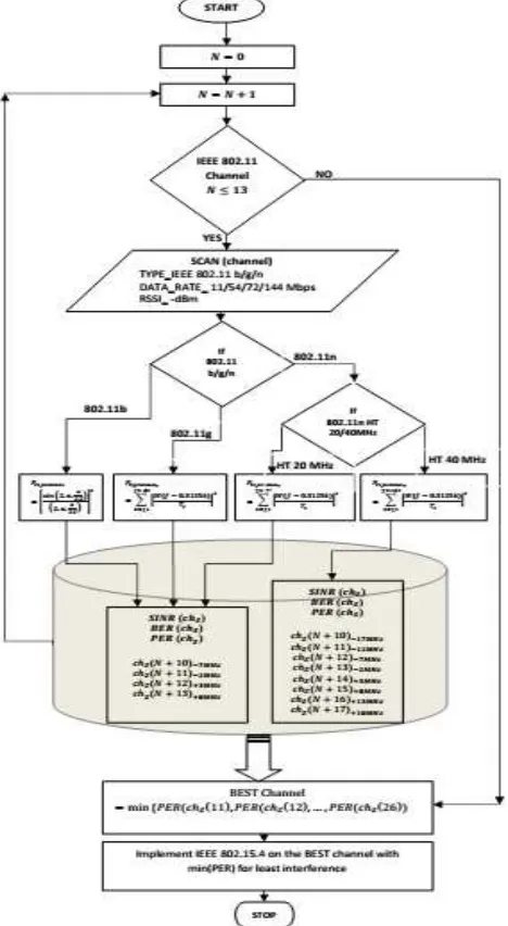
3) Cognitive Radio Algorithm for optimum performance channel allocation to minimize interference
Fig:11 Proposed Cognitive Radio Algorithm based on Spectrum sensing to mitigate interference on IEEE 802.15.4 in the presence of IEEE 802.11 b/g/n interference sources
The minimum interference radio channel is given as Best Channel of deployment as given in equation (19).
4) Cognitive Radio Algorithm implementation of low-power IoT nodes
From the perspective of a deployment Internet of Things Sensor/Actuators nodes based on of IEEE 802.15.4 Zigbee Network, the nodes are low data rate and low power devices specially designed for longer service time powered by limited battery life. The Cognitive Radio algorithm proposed above is having some significant amount of computational requirement especially to calculate SINR(chz), BER(chz) and PER(chz) based on received , which in terms consume of vital battery life and reduce the service time of such IoT motes. To deal with the above problem the proposed architecture in the scenario of low power IoT devices can be further optimized by implementing the modified CR algorithm.
The modified CR algorithm is to make the algorithm less computationally regressive by aiding all the possible channel overlapping scenario interference pattern as per Table 1 & 2. The SINR(chz), BER(chz) and PER(chz) can be pre-calculated and stored in a database of the IoT motes. The database file size is also minimum possibly three files b/g/n 20MHz and one file for n 40Mhz overlapping scenario. Each file would content PER(chz) for IEEE 802.11 b/g/n 20 MHz 4 Overlapping pattern x 14 = 56 float data type i.e 672 bytes total for three files. The IEEE 802.11 n 40Mhz overlapping pattern 8 x 8 channel =64 float i.e. 256 bytes Table. Total required database size is 928 bytes. Thus the whole set of learning data set can be implemented no more than 1 KB database, which can be easily implementable in IoT motes. The IoT motes aided with spectrum sensing can determine the radio channel overlapping scenario between the IEEE 802.15.4 network and the interference source as IEEE 802.11. One the overlapping pattern is finding as per Table 1 & 2, the expected PER(chz) would be taken from the look-up table of the databases just been discussed above and finally implementing equation (19) the best channel with least interference can be selected and the IoT mote will select that as its radio channel to communicate in the PAN.
III.RESULTS AND DISCUSSION
The decisive parameter for performance here is considered as Packet Error Rate (PER) [17]. PER is having more significance than BER as it includes the data-link layer timing parameters as given in Table.4 for IEEE 802.11 b/g/n and in Table.5 for IEEE 802.15.4 into consideration. Equation (18) shows the PER with is BER of IEEE 802.15.4 with interference from IEEE 802.11b/g/n. BER is the performance parameter only considering the physical layer. To get a more accurate and holistic measure of the impact of interference even data link layer parameter would play a significant role, especially the packet size and inter-arrival rate as mentioned in equation (12) for IEEE 802.11 and equation (13) for IEEE 802.15.4 in a time unit.
The calculation of Collision time: as a different time-offset is the key to find out the overlapping of packets when both are network are sending packets in the same radio channel without considering other’s presence is an indicator of collision between IEEE 802.11 and IEEE 802.15.4.
This paper has further validating results indicated by the test-bed that even for higher data-rate variants of IEEE 802.11n the interference in getting minimized as the time offset overlapping between it and XBEE® IEEE 802.15.4 PAN is getting minimized as indicated by Fig.8. Thus it is evident that spectral overlapping with higher power IEEE 802.11 network is having a deteriorating impact on low power IEEE 802.15.4 on SINR any eventually having a higher BER is not the key parameter of performance. In addition to this, the Collision time: between IEEE 802.15.4 and IEEE 802.11 b/g/n is the key to get the performance of IEEE 802.15.4 under the influence of IEEE 802.11 b/g/n interference.
peak PER value is around 0.375 analytical value and 0.355 empirical test-bed values for the maximum spectral overlapping scenario with a minimum frequency offset of 2 MHz. PER values are significantly higher of distance up to 2-3 meters. When the distance “d” between IEEE 802.15.4 and IEEE 802.11 increases further the PER drops down and become nominal.
Fig.12: Packet Error Rate of IEEE 802.15.4 (ZigbeeTM) in the presence of interference Source IEEE 802.11b DSSS 22MHz (2401-2423 MHz) Channel 1: (Center Frequency at 2412 MHz)
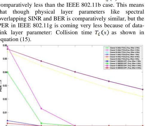
Fig.13 shows the PER vs. “d” distance form XBEE® IEEE 802.15.4 PAN to IEEE 802.11g network the frequency offset are taken from Table.1 The solid lines and analytically calculated values using MATLAB and dotted line empirical values obtained from the test bed as shown in Fig.14. The peak PER value is around 0.06 both analytical, empirical test-bed values for the maximum spectral overlapping scenario with a minimum frequency offset of 3MHz. PER values are significantly higher of distance up to 2-3 meters. When the distance “d” between IEEE 802.15.4 and IEEE 802.11 increases further the PER drops down and become nominal. As compared to the IEEE 802.11b interference this IEEE 802.11g is very less. This phenomenon can be corroborated with the Collision time: which is comparatively less than the IEEE 802.11b case. This means that though physical layer parameters like spectral overlapping SINR and BER is comparatively similar, but the PER in IEEE 802.11g is coming very less because of data-link layer parameter: Collision time as shown in equation (15).
Fig. 13: Packet Error Rate of IEEE 802.15.4(ZigbeeTM) in the presence of interference Source IEEE 802.11g OFDM 20MHz (2402-2422MHz) Channel 1: (Center Frequency at 2412 MHz)
Fig.14 shows the PER vs. “d” distance form XBEE® IEEE 802.15.4 PAN to IEEE 802.11n HT 20MHz network the frequency offset are taken from Table.1 The solid lines and analytically calculated values using MATLAB and dotted line empirical values obtained from the test bed as shown in Fig.14. In this case, the peak PER value is around 0.045 both analytical, empirical test-bed values for the maximum spectral overlapping scenario with minimum frequency offset of 3MHz. This scenario is almost analogous to the IEEE 802.11g case with little peak PER change of 0.015 can be explained by the further less Collision time as shown in equation (16).
Fig.14: Packet Error Rate of IEEE 802.15.4 (ZigbeeTM) in the presence of interference Source IEEE 802.11n HT 20MHz OFDM (2402-2422MHz) Channel 1: (Center Frequency at 2412 MHz)
Fig.15 shows the PER vs. “d” distance form XBEE® IEEE 802.15.4 PAN to IEEE 802.11n HT 40MHz network the frequency offset are taken from Table.1 The solid lines and analytically calculated values using MATLAB and dotted line empirical values obtained from the test bed as shown in Fig.14. The peak PER value is around 0.025 for the analytical model and 0.015 for empirical test-bed values for the maximum spectral overlapping scenario with the minimum frequency offset of 3MHz. This scenario is almost analogous to the IEEE 802.11n HT 20MHz case with little peak PER change of 0.020 can be explained by the further less Collision time as shown in Figure 12, which is by equation (17).
Fig.15 : Packet Error Rate of IEEE 802.15.4 (ZigbeeTM) in presence of interference Source IEEE 802.11n HT 40 MHz OFDM (2402-2442MHz) Channel 1 + 5 : (Center Frequency at 2422 MHz)
The scope of this paper includes not only to quantify the matrices for interference but also to suggest a mitigation technique specially designed for the IoT deployment environment using heterogeneous wireless networks. In the further research, a Cognitive Radio algorithm should be proposed based on the real-time spectrum sensing technique. This algorithm would be implemented based on the interference index obtained from the testbed as well as the analytical model. The Cognitive Radio Algorithm will take decisions to select an optimum radio channel for IEEE 802.15.4 Zigbee PAN network, which will help in mitigating the interference from adjacently deployed IEEE 802.11 b/g/n network. The Cognitive Radio Algorithm will consider the BER for all possible spectral overlapping conditions and Collision time to finally get PER to decide least PER channel deployment to mitigate interference.
IV.CONCLUSION
This paper has suggested a Cognitive Radio Algorithm for IoT motes deployment scenario using IEEE 802.15.4 Zigbee WPAN to mitigate interference from IEEE 802.11 b/g/n sources. The Cognitive Radio Algorithm is proposed based on the impact of such interface using analytical model, corroborated by experiments performed using XBEE® IEEE 802.15.4 Zigbee motes in the presence of IEEE 802.11 b/g/n interference source.
ACKNOWLEDGMENT
This paper is motivated from the Internet of Things (IoT) deployment done in School of Electronics Engineering, KIIT Deemed to be University, Bhubaneswar using Digi International XBEE® (Zigbee) IEEE 802.15.4 based motes. The campus has a distribution of considerable number of the WiFi access point and also Reliance Jio Access point: IEEE 802.11 b/g/n. The XBEE® motes deployed in the proximity to such IEEE 802.11 access point suffers severely as PER is much higher to motes placed remotely to such IEEE 802.11 interference sources.
REFERENCES
[1] M. Surligas, A. Makrogiannakis, and S. Papadakis, "Empowering the IoT Heterogeneous Wireless Networking with Software Defined Radio," 2015 IEEE 81st Vehicular Technology Conference (VTC Spring), Glasgow, 2015, pp. 1-5.
[2] L. D. Xu, W. He and S. Li, "Internet of Things in Industries: A Survey," in IEEE Transactions on Industrial Informatics, vol. 10, no. 4, pp. 2233-2243, Nov. 2014.
[3] A. Zanella, N. Bui, A. Castellani, L. Vangelista and M. Zorzi, "Internet of Things for Smart Cities," in IEEE Internet of Things Journal, vol. 1, no. 1, pp. 22-32, Feb. 2014.
[4] Z. Sheng, S. Yang, Y. Yu, A. V. Vasilakos, J. A. Mccann and K. K. Leung, "A survey on the ietf protocol suite for the internet of things: standards, challenges, and opportunities," in IEEE Wireless Communications, vol. 20, no. 6, pp. 91-98, December 2013. [5] N. Ahmed, H. Rahman, Md.I. Hussain, “A comparison of 802.11ah
and 802.15.4 for IoT”, In ICT Express, Volume 2, Issue 3, 2016, Pages 100-102, ISSN2405-9595.
[6] Soo Young Shin, Hong Seong Park, Wook Hyun Kwon, Mutual interference analysis of IEEE 802.15.4 and IEEE 802.11b, ScienceDirect, Computer Networks 51 (2007) 3338–3353.
[7] HUO Hong-wei, XU You-zhi, Mikael Gidlund, ZHANG Hong-ke, Coexistance of 2.4 GHz sensor networks in home environment, www.Sciencedirect .com/science/journal/10058885,February2010, 17(1) : 9-18.
[8] IEEE Standard for Information technology-- Local and metropolitan area networks-- Specific requirements-- Part 11: Wireless LAN Medium Access Control (MAC)and Physical Layer (PHY) Specifications Amendment 5: Enhancements for Higher Throughput," in IEEE Std 802.11n-2009 (Amendment to IEEE Std 802.11-2007 as amended by IEEE Std 802.11k-2008, IEEE Std 802.11r-2008, IEEE Std 802.11y-2008, and IEEE Std 802.11w-2009) , vol., no., pp.1-565, Oct. 29 2009.
[9] Kandeepan Sithamparanathan, Andrea Giorgetti; “Cognitive radio techniques : spectrum sensing, interference mitigation, and localization” Boston : Artech House, [2012] ISBN:1608072037. [10] 802.15 Working Group, IEEE 802 Coexistence analysis of IEEE Std
802.15.4 with other IEEE standards and proposed standards, September 2010, IEEE P802.15-10-0808-00.
[11] IEEE Std 802.15.4™-2015 (Revision of IEEE Std 802.15.4-2011) IEEE Standard for Low-Rate Wireless Networks, IEEE Computer Society ISBN 978-1-5044-0846-2.
[12] G. Villegas, L. Aguilera, V. Ferŕe, P. Aspas et al., "Effect of adjacent channel interference in IEEE 802.11 WLANs, " in 2nd International Conference on Cognitive Radio Oriented Wireless Networks and Communications (CrownCom). IEEE, 2007, pp. 118-125.
[13] OFDM Baseband Receiver Design for Wireless Communications Tzi-Dar Chiueh and Pei-Yun Tsai© 2007 John Wiley & Sons (Asia) Pte Ltd. ISBN: 978-0-470-82234-0.
[14] Rajeev Piyare, Seong-ro Lee, “Performance Analysis of XBee ZB Module Based Wireless Sensor Networks” International Journal of Scientific & Engineering Research, Volume 4, Issue 5, May-2013. ISSN 2229-5518.
[15] W. Yuan, X. Wang, J. M.G. Linnartz, "A Coexistence Model of IEEE 802.15.4 and IEEE 802.11 b/g", Proceedings of the 14th IEEE Symposium on Communications and Vehicular Technology in the Benelux, p. 1-5, 2007.
[16] Thomas Paul and Tokunbo, Ogunfunmi, "Wireless LAN Comes of Age: Understanding the IEEE 802.11n Amendment” IEEE CIRCUITS AND SYSTEMS MAGAZINE 1531-636X/08/$25.00 IEEE FIRST QUARTER 2008.