PG Student Professor
Department of Mechanical Engineering Department of Mechanical Engineering Dr.J.J.Magdum College of Engineering, Jaysingpur, Shivaji
University, Kolhapur, India
Dr.J.J.Magdum College of Engineering, Jaysingpur, Shivaji University, Kolhapur, India
Abstract
Reliability Analysis by Fault Tree Analysis (FTA) method plays crucial role in design process. FTA is a graphical representation of major failure occurs in a machine, their causes of failures and potential countermeasures. This paper deals with a reliability analysis of vertical broaching machine by FTA method. Qualitative and quantitative analysis helps to identify the critical design parameters and maintenance suggestions.
Keywords: Vertical Broaching Machine, Reliability Analysis, FTA Method, Qualitative Analysis
_______________________________________________________________________________________________________
I. INTRODUCTION
In today’s competitive world, reliability analysis of equipment or machine is extremely important to maintain quality with delivery deadlines. This can achieve by using proper maintenance and design changes for unreliable subsystem and components of a complex system. It is significant to develop the strategy for maintenance, replacement and design changes related to those subsystems or components. An analysis of down time along with causes is essential to identify the unreliable components and subsystems. The growing awareness of reliability arises from the fact that there is a need for efficient, economic and continuous running of equipment or system in any organization for achieving the targeted production at a minimum cost to face the present competition. The word reliability is associated with the civilization of mankind to compare one item or person with another. Trustworthy, dependable and consistent are the words, which can be used to give an indication of why the characteristic of reliability is so much valued [1]. Reliability cannot be precisely measured with respect to human behavior but it can give an indication that a particular person is more reliable than the other. The characteristic of reliability is usually used to describe some function or in widest sense, it may be said to be a measure of performance.
The complexity of industrial systems as well as their products is increasing day-by-day. The improvement in effectiveness of complex systems has therefore acquired special importance in the recent years. The effectiveness of system is understood to mean the suitability of the system for the fulfillment of the intended tasks and the efficiency of utilizing the means put into it [2]. The suitability of performing definite tasks is primarily determined by reliability and quality of the system. Keeping this in view it was proposed to carry out reliability, maintainability and life cycle cost analysis of a Vertical Broaching Machine based on time to failure and time to repair data. This work is sponsored by G.S.Engineers, Ichalkaranji. The main objective was to study failure patterns of selected Vertical Broaching Machine and to develop a reliability model to estimate reliability.
Vertical Broaching Machine
Fig. 1: Vertical Broaching Machine
Table – 1
Specification of Vertical Broaching Machine
Parameters Specification
Pulling capacity 6000 kg
Cylinder Make Hydrotech
Bore dia. 63 mm
Piston rod dia. 45 mm
Maximum stroke 1200 mm
Cutting speed ( variable ) 1.0 to 5 mtrs/min
Return Speed 6 mtrs/min
Face plate dimensions 325×680 mm
Maximum shank dia. A or B as per DIN 1415/1417 25 mm- 32mm
Dia. of bore in false plate 200H7 mm
Power of electric motor 7.5 HP /1500 rpm
Power of coolant motor 0.37 kw (0.5 H.P)
Operating Pressure at full load 90 kg /cm.sq
Hydraulic capacity 210 litres
Coolant fluid reservoir capacity 180 litres
Fault Tree Analysis Method
Fault tree analysis (FTA) is the commonly used technique to analyze failure patterns of engineering and biological systems. Fault tree analysis is a failure analysis in which an undesired state of a system is analyzed using Boolean logic to combine a series of lower level events. It is basically composed of logic diagrams that display the state of the system and is constructed using graphical techniques [3]. This analysis method is mainly used in the fields of safety engineering and reliability engineering to understand how systems can fail, to identify the ways to reduce risk or to determine event rates of a safety accident or a particular system level failure. FTA is used in the aerospace, nuclear power, chemical and process, pharmaceutical, petrochemical and other high-hazard industries; but is also used in fields as diverse as risk factor identification relating to social service system failure.
Fault Tree Analysis was originally developed in 1962 at Bell Laboratories by H.A.Watson, under a U.S Air Force Ballistics System Division. It was later adopted and extensively applied by Boeing Company. FTA is a top-down approach to failure analysis, starting with a undesirable event called TOP event, and then determining all the ways that TOP event can occur.
Fault tree analysis can help to prevent failures from occurring by providing with data showing how and under what circumstances the failure could occur, allowing for alternative measures to prevent the failures or hazards. The Boolean methodology and equations are used to construct and simplify the fault tree. As fault trees are constructed, the Boolean equations are used to evaluate the qualitative and quantitative characteristic of a system.
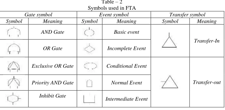
Symbols used in FTA Method
OR Gate Incomplete Event
Exclusive OR Gate Conditional Event
Transfer-out
Priority AND Gate Normal Event
Inhibit Gate
Intermediate Event
Steps Involved in FTA Method
There are five major steps to a fault tree analysis [4]: 1) Define the system, its boundaries, and the top event.
2) Construct the fault tree, which symbolically represents the system and its relevant events.
3) Perform a qualitative evaluation by identifying those combinations of events that will cause the top event.
4) Perform a quantitative evaluation by assigning failure probabilities or unavailability to the basic events and computing the probability of the top event.
5) Interpret and present the results
II. DESIGN AND CONSTRUCTION DETAILS OF VERTICAL BROACHING MACHINE
Design Consideration
It is very essential to consider certain design parameters while designing any system. These considerations decide quality, capacity, performance and efficiency of the system. To achieve some of these objectives, certain design considerations have been made for Vertical Broaching Machine. These design considerations for Vertical Broaching Machine are given below.
A broach always moves forward and in straight line, so that all the elements of the broached surface must be parallel to the axis of the travel.
The ideal hardness range for broaching is from 12 to 22 HRC.
All machinable materials, metallic or nonmetallic, can be broached. Some of the newer materials like nickel base and heat-resisting alloys can also be broached with care.
The pulling capacity of machine is 6000 kg and stroke length is 1200mm.
The main frame consists of upper table (face plate), lower table and two columns. This frame is clamped on a fabricated structure.
The two hydraulic cylinders are clamped to the upper table to pull the broach on upper side.
Because of rigid construction the machine is firmly mounted on leveled floor and it is secure to the floor through the four holes of M16 provided in the machine.
The maximum rapid return speed of broach is 6m/min.
Machine should be installed in such a way as to isolate all the vibrations. Machine must be accurately leveled both in longitudinal and transverse direction by the use of precision level.
The crosshead has two oil nipples. They must be filled with lubricating oil.
The height of the main frame and other equipments is selected such that maintenance work will require less effort. Proper damping system should be there in order to damp shocks coming from cutting tools.
Different components are designed in order to minimize cost of the system to compete with competitors.
Construction Details
The important construction and operational features of the Vertical Broaching Machine are given below. Broach
Fig. 2: Parts of a Broaching Tool
Feed is accomplished by the increased step between any two successive teeth on the broach. The total material removed in a single pairs of broach is the cumulative result of all the teeth in the tool in action. The cutting speed of the broach is decided by the linear travel of the tool with respect to the work piece.
Common broach material is 18-4-1 stainless steel as its name indicates; it has 4%chromium, 1%vanadium, 18%tungsten. This is corrosion and wear resistant steel. Carbide is also recommended for broach making, these broaches are used for broaching brittle material like cast iron in automobile industry. Inserted bit type and cemented carbide type broaches are also preferred to reduce the cost of broaches.
Hydraulic Power Pack
Fig. 3: Hydraulic Power Pack Assembly
It consists of electrical induction motor and gear pump which is connected to manifold and with help of pressure control valve as well as direction control valve, hydraulic oil is transferred to hydraulic cylinder and to hydraulic pump to move crosshead on vertical columns to pull the broach in forward stoke to complete the broaching operation on component. The speed of the broaching is variable by means of a flow control valve.
Electrical Control Panel
Fig. 4: Control Panel
It consist of no. of push buttons present on it, some of them are like hydraulic ON, Broach UP, Broach Down, Coolant ON/Off, Ram Stop, Power ON etc. The operation of individual is given below.
Hydraulic ON- This is push button control. Coolant pump motor starts with switch ‘ON’, however, the coolant flow can be stopped with the control valve on the head.
Broach UP/Down- The broach start and stops the operation depends upon control panel and solenoid valve operation which actuates the hydraulic cylinder.
Fig. 5: Puller jaw system
III. CONSTRUCTION OF FAULT TREE OF VERTICAL BROACHING MACHINE
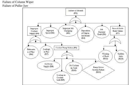
The main objective of Vertical Broaching Machine is to machining of the job with high machining accuracy and high productivity. Therefore, failure to do machining is considered as top event. The failure of Vertical Broaching Machine is because of eleven reasons. First reason is failure of broach. There are number of factors affecting the failure of the broach which are considered as intermediate events. Second reason is failure of hydraulic system failure; it is also a dependent event so it is an intermediate event. Third reason is electrical control system failure; it is also a dependent event so it is also an intermediate event. Fourth reason is failure of column wiper. Fifth reason is failure of puller jaw. Sixth reason is improper coolant supply. Seventh reason is failure of broach guide bush. Eighth reason is failure of coolant pump. Ninth reason is failure of oil seal. Tenth reason is flow control valve failure. Eleventh reason is filter failure. Twelfth reason is connector failure. These are the twelve reasons to failure of Vertical Broaching Machine. There are total five main reasons (top sub events) of failure, which are given below,
Failure of Broach Hydraulic System Failure Electrical Control System Failure Failure of Column Wiper Failure of Puller Jaw
Fig. 7: Electrical Control System Failure
Fig. 8: Hydraulic System Failure
Fig. 9: Failure of Puller Jaw
F1 =X2 + X3 + X4 + X5+ X6 + X7 + X8 + X9+ X10+ X11+ X12+ X13 F2 = X14 + X15+F9 +F10+F11+F12+X20
But, F9 = X16+X17, F10 = X18+X19, F11 = X21, F12 = X22; Therefore, F2 = X14+X15+X16+X17+X18+X19+X20+X21+X22
F3 = X23+X24+X25+X26+X27+X28+X29
F4 = X30+F13, But, F13 = X31+X32+F14, F14 = X33+X34+X35+X36, Therefore, F4 = X30+X31+X32+X33+X34+X35+X36
F5 = X37+X38+X39+X40
Putting values of F1, F2, F3, F4, F5, in equation of F, we get,
F = X1 + X2 + X3 + X4 + X5+ X6 + X7 + X8 + X9 + X10 + X11 + X12 + X13 + X14 + X15 + X16 + X17 + X18 + X19 + X20 + X21+ X22 + X23+ X24 + X25 + X26 + X27 + X28+ X29 + X30 + X31+ X32+X33 + X34+ X35 + X36 +X37 +X38 +X39 +X40
V. QUANTITATIVE ANALYSIS
For the given analysis, it is considered that power supply is constant and continuous. The components except X1, X11, X16, X20, X21, X22, X23, X27 and X36 are suggested for preventive maintenance. Hence reliability of the system is the resultant of reliabilities of components X1, X11, X16, X20, X21, X22, X23, X27 and X36. Therefore final equation takes the following form and same is used to estimate system reliability.
Rs = R1 × R11 × R16 × R20 × R21 × R22 × R23 × R27 × R36
Here Hydraulic oil seal, Hydraulic pipe and Hydraulic power pack motor had very low reliability for a period of one year. Hence these are also kept for preventive maintenance.
Therefore above equation takes the following form and this equation is used to find the system reliability. Rs= 0.9707 × 0.8801 × 0.8163 × 0.9941 × 0.9208 × 0.8226
Rs = 0.53
Thus, the reliability of Vertical Broaching Machine by fault tree analysis method is 0.53.
VI. RESULT AND CONCLUSION
Fault Tree Analysis directly focuses on the modes of failure, which is more effective method than other method like system reliability block diagram. Symbols used in FTA method are easy to understand. The tool helps to identify areas of concern for new product design or for improvement of existing products. It also helps to identify corrective actions to correct or mitigate problems. Reliable failure data is essential for analysis. It provides a clear and concise means of imparting reliability information to management.
REFERENCES
[1] Charles E. Ebling,“Introduction to Reliability and Maintainability Engineering”, TataMc-Graw Hill Publishing, House, Edition 2000.
[2] JavadBarabady, Uday Kumar,“ Reliability Analysis of Mining Equipment: A Case Study of a Crushing Plant at Jajarm Bauxite Mine in Iran”, Reliability Engineering and System Safety, page no. 647-653, 2008.
[3] L. Y. Waghmode, R. B. Patil, “An Overview of Fault Tree Analysis (FTA) Method for Reliability Analysis.” Journal of Engineering Research and Studies, Volume 4, page no. 6-8, January 2013.
[4] Mohammad SadeghJavadi, AzimNobakht, Ali Meskarbashee,“ Fault Tree Analysis Approach in Reliability Assessment of Power System”, International Journal of Multidisciplinary Sciences and Engineering, volume.2, No.6, September 2011.