Modelling of Single-Phase to Three-Phase Power
Conversion System with Uncontrolled/Controlled Bridge at
Input Side
Dheeraj Panchauli
M. Tech. Student, Rajasthan Technical University, Kota, India, [email protected]
Ashok Kumar Sharma
Associate Professor, Rajasthan Technical University, Kota, India, [email protected]
Abstract – This paper presents modelling of single phase to three phase conventional converter with uncontrolled and controlled bridge at input converter side. The input current of rectifier and output voltage of inverter is analysed. Initially single phase a.c power is converted into d.c power using diode bridge rectifier which is further converted into three phase a.c power with the help of three arms IGBT Inverter Bridge. A DC-link capacitor, is interlinked between the two stages of power conversion. The Pulse Width Modulation (PWM) control and Hysteresis Current Control (HCC) techniques have been used in rectification and inversion processes. The proposed topology permits to reduce the rectifier switch currents, the harmonic distortion at the input converter side, and improves the fault tolerance characteristics. The model is developed with the help of SIMULINK tool box of the MATLAB software. Keyword – Power conversion, Power electronics converters, Parallel converter, Pulse width modulation.
1. I
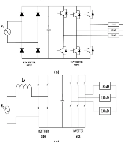
NTRODUCTIONIn the power distribution system, the single phase grid is considered as an alternative for rural or remote areas due to its lower cost, compared to the three phase grid. On the other hand, loads connected in a three phase arrangement presents some advantages when compared to single phase loads. Three phase motor system with variable–speed drives has advantage due to their constant torque characteristics.so there is a need for single phase to three phase power conversion system for above purpose. The direct solutions for the single-phase to three-phase power converters is presented in Fig. 1.1.
AC
VS RECTIFIER INVERTER
LOAD LOAD
LOAD
Fig. 1.1. Block diagram of single phase to three phase power converter
AC
LOAD LOAD
VS
INVERTER SIDE RECTIFIER
SIDE
LOAD
(a)
AC
LOAD
LOAD
V
SL
SRECTIFIER SIDE
INVERTER SIDE
LOAD
(b)
Fig. 1.2. Conventional single-phase to three-phase drive system with (a) uncontrolled (b) rectifier controlled
rectifier
conversion, in which all variables (e.g., input power factor and dc-link voltage) at input–output converter sides can be controlled, On the other hand, the configuration presented in Fig. 1(a) represents a cheaper solution but without any control of the input current and dc-link voltage. This is essential in some applications such as aerospace, wind turbine, or UPS for main frame computers and servers. the proposed system permits: to reduce the rectifier switch currents; the total harmonic distortion (THD) of the grid current with same switching frequency or the switching frequency with same THD of the grid current; and to increase the fault tolerance characteristics.
2. S
YSTEMM
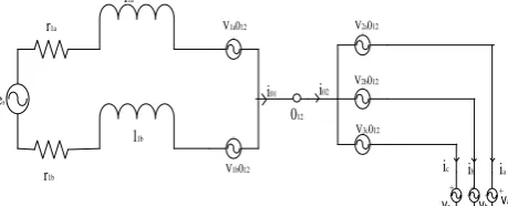
ODELThis section will present the model of the proposed configuration. Such a configuration is constituted by a single-phase grid, one open-end three-phase motor, inductor filters (L1a, L1b), converters 1, 2 and one dc-link capacitor banks (C12). If the legs are substituted by pulsed voltage sources, the proposed converter can be modelled as in Fig.2.1.
AC
AC
AC
AC
AC
AC AC AC
es r1a
l1a
V1a012
V1b012
i01 i02
012
r1b
l1b
V2a012
V2b012
V3c012
va
vb
vc
+ + +
ic ib ia
Fig. 2.1. Simplified model of the single-phase to three-phase conversion system C1 configuration
2.1. Source -Side Converter Model
From the system in Fig. 2.1, the following equations can be derived to converters 1 at the grid side:
1a 1b
g 1a 1a 1a 1a 1b 1b 1
di
di
e = r i +l
-r i -l
+v
dt
dt
……….(1)
g 1a
i = i
……….(2)
With
1 1a 12 1b 12
v = v
0
- v 0
………(3)
Where i1a and i1b are the input currents of the converter 1,
the symbols r and l represent the resistance and inductance of inductors L1a, L1b. The voltages v1a01 2 and
v1b01 2 are the pole voltages of the converter 1, and Is is
the source current.
2.2. Machine-Side Converter Model
From the system in Fig.2.1, the following equations can be derived to converters 2 at the machine side:
ab 2a 12 2b 12
v = v 0 - v 0
………(4)
bc 2b 12 2c 12
v = v 0 - v 0
………(5)
ca 2c 12 2a 12
v = v 0 - v 0
………(6)
Where v2a012, v2b012, and v2c012 are the pole voltages of
converter 2, and vab = va − vb, vbc = vb − vc, and vca = vc –
va are line-to-line voltages of the machine. For the
voltage control of the motor, the following relations are obtained:
ab 2ab 2a 12 2b 12
v
v
= v 0 - v 0 =
2
……….(7)
bc 2bc 2b 12 2b 12
v
v
= v 0 - v 0 =
2
………...(8)
ca 2ca 2c 12 2a 12
v
v
= v 0 - v 0 =
2
………(9)
2.3. Circulating Current Model
Due to the series connection, the proposed
system shown in Fig.2.1 has a circulating
current among the converts. The model of this
circulating current can be defined as following:
za 1a 12 2j 12 j
0 = v + v 0 + v 0 + v
………..………(10)
zb 1b 12 2j 12 j
0 = v + v 0 + v 0 + v
………….(11)
With
j
=
a, b, c
and
1a za 1a 1a 1a
di
v = r i + l
dt
………(12)
1b zb 1b 1b 1b
di
v = r i + l
dt
……….(13)
The equations of the input circulating currents of the converters 1 io1 and output circulating currents of the
converters 2 io2 are defined as
01 1a 1b
i = i + i
………(14)
02 2a 2b 2c
i = i + i + i
……….(15)
However, the circulating currents io1, io2, can be represented by a single circulating current io, which
means
0 01 02
i = i = i
………..(16)
From (10) and (11), it is possible to write
0
0 01 1b o 1b j
di
2
v = v + r i + l
+
v
dt
3
c
j a
………
(17)
With
1a 01 1a 1b 1a 1a 1b
di
v = (r -r )i + (l -l )
dt
………(18)
b
o 1i 12 2j 12
i=a j=a
2
=
3
v
v 0
v 0
c
………..
(19)
2.4. Three-Phase Motor Model
sdq sdq s sdq
d
v
= r i
+
dt
……….(20)
rdq
rdq r rdq r rdq
d
v
= r i
+
-jω
dt
………..(21)
sdq
= l i
s sdq+ l i
sr rdq ………(22)
rdq
= l i
sr sdq+ l i
r rdq ………...(23)
s0s0 s s0 ls
di
v = r i + l
dt
………..(24)
r0 r0 r r0 lr
di
v = r i + l
dt
………..
(25)
e sr sq rd sd rq
T = Pl (i i - i i )
………..
(26)
where vsdq = vsd + jvsq , isdq = isd+jisq , and φsdq = φsd + jφsq
are the voltage, current, and flux dq vectors of the stator, respectively; vso and iso are the homopolar voltage and
current of the stator, respectively (the equivalent rotor variables are obtained by replacing the subscript s by r); Te is the electromagnetic torque; ωr is the angular
frequency of the rotor; rs and rr are the stator and rotor
resistances; ls, lls, lr , and llr are the self and leakage
inductance of the stator and rotor, respectively; lsr is the
mutual inductance and P is the number of pole pairs of the machine. The dqo stator variables of the previous model can be determined from the abc variables by using the transformation given by
sdq0 s abc
ω
= A ω
………(27)
With
ω
sdqoω ω ω
sd sq s0 T,
abc
ω
and
s
A
=
1
1
1
-
-2
2
2
3
3
0
-3
2
2
2
2
2
2
2
2
3. C
ONTROLS
TRATEGYThe control signals are obtained by comparing pole voltages with one (vt1), or more high-frequency triangular carrier signals. In the case of double-carrier approach, the phase shift of the two triangular carrier signals (vt1 and vt2) is 1800. The parameter µ changes the place of the voltage pulses related to Va and Vb. When Vx* = Vx*min (µ = 0) or Vx* = Vx*max (µ = 1) are selected, the pulses are placed in the beginning or in the end of half period (Ts) of the control block diagram of Fig. 3.1, highlighting the control of the rectifier. To control the dc-link voltage and to guarantee the grid
power factor close to one. Additionally, the circulating current Io in the rectifier of the proposed system needs to be controlled.
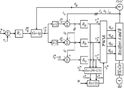
the dc-link voltage vc is adjusted to its reference value v c* using the controller Rc, which is a standard PI type controller. This controller provides the amplitude of the reference grid current Is*. To control power factor and harmonics in the grid side, the instantaneous reference current Is* must be synchronized with voltage e.g., as given in the voltage-oriented control (VOC) for three-phase system. This is obtained via blocks Ge-ig, based on a PLL scheme Fig 3.1. The reference currents I a*and ib* are obtained by making Ia* = Ib* = Is* /2, which means that each rectifier receives half of the grid current. The control of the rectifier currents is implemented using the controllers indicated by blocks Ra and Rb. These current controllers define the input reference voltages Va*and Vb*. The homo polar current is measured (Io) and compared to its reference (Io* = 0). The error is the input of PI controller Ro, that determines the voltage Vo*. The motor there-phase voltages are supplied from the inverter (VSI). Block VSI-Ctr indicates the inverter and its control. The control system is composed of the PWM command and a torque/flux control strategy.
Fig. 3.1. Control block diagram
4. H
ARMONICD
ISTORTIONAs we know that harmonic distortion of the proposed converter and its voltages had been analysed with the help of weighted THD (WTHD). It is solved by using
Where is treated as amplitude of fundamental voltage and is treated as amplitude of Ith harmonic and also p may be number of harmonics in this consideration.
5. S
IMULATIONM
ODELTo study the operation of the Three-Phase Drive System,
it is implemented in MATLAB/SIMULINK
Discrete, Ts = 5e-06 s.
powergui v + -v + -A B C a b c A B C a b c a b c A B C a b c A B C + + + Scope5 Mean Mean g m C E g m C E g m C E g m C E g m C E g m C E Vdc Vs Is Is Vs Iabc_i_op Vabc_i_op g2 g4 g6
g5 Iabcload Vabcload Vabc_i_op Vabcload Vdc g3 g1 i + -ControlSignal
<Switch v oltage> <Switch current>
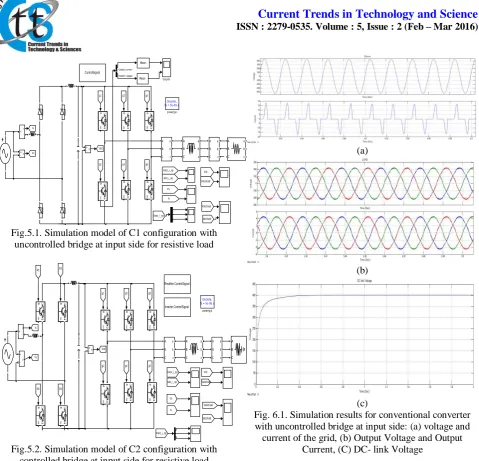
Fig.5.1. Simulation model of C1 configuration with uncontrolled bridge at input side for resistive load
Discrete, Ts = 5e-06 s.
powergui v + -v + -A B C a b c A B C a b c A B C a b c A B C + + + g m C E g m C E g m C E g m C E g m C E g m C E g m C E g m C E g m C E g m C E Vdc Vs Is Is Vs Iabc_i_op Vabc_i_op g2 g4 g6
g5 R2 R4 R1 R3 Iabcload Vabcload Vabc_i_op Vabcload Vdc g3 g1 i + -Rectifire ControlSignal Inverter ControlSignal
Fig.5.2. Simulation model of C2 configuration with controlled bridge at input side for resistive load
6. R
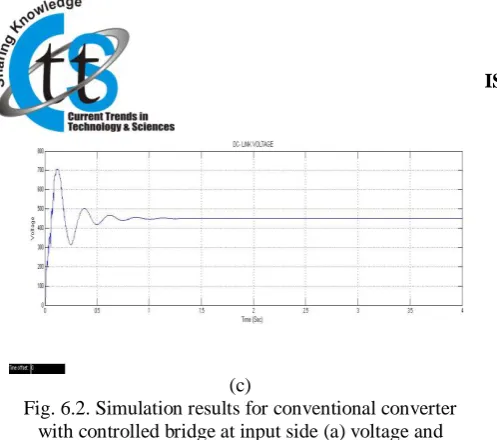
ESULTThe simulation results were obtained with the source and load -phase voltages equal to Vrms440/√2, dc-link voltage of 400 V, capacitance of 2200 μF, and input inductor filters with resistance and inductance given respectively by 0.1Ω and 2.6 mH. Fig. 6.1 (a) shows the ability of the conventional converter with uncontrolled bridge at input side to control the source current with a sinusoidal waveform and power factor close to one. While Fig. 6.1 (b) and (c) shows that wave form of Output Voltage and Output Current. And DC-link voltage for conventional system. Fig. 6.2 shows the wave form of source Voltage and source Current, Output Voltage and Output Current and DC-link voltage for with controlled bridge at input side
(a)
(b)
(c)
Fig. 6.1. Simulation results for conventional converter with uncontrolled bridge at input side: (a) voltage and current of the grid, (b) Output Voltage and Output
Current, (C) DC- link Voltage
(a)
(c)
Fig. 6.2. Simulation results for conventional converter with controlled bridge at input side (a) voltage and
current of the grid (b) Output Voltage and Output Current, (C) DC- link Voltage
7. C
ONCLUSIONA single-phase to three-phase drive system with uncontrolled/controlled bridge at input side and a three phase load was proposed. The system model and the control strategy, including the PWM technique, have been developed. The complete comparison between the proposed and standard configurations has been carried out in this paper. Compared to the conventional topology, the proposed system permits to reduce the rectifier switch currents, the THD of the grid current with same switching frequency or the switching frequency with same THD of the grid current and to increase the fault tolerance characteristics. In addition, the losses of the proposed system may be lower than that of the conventional counterpart. The initial investment of the proposed system (due to control of semiconductor devices) cannot be considered a drawback, especially considering the scenario where the cited advantages justify such initial investment. The experimental results have shown that the system is controlled properly, even with transient and occurrence of fault.
R
EFERENCE[1] A. H. Maggs, ―Single-phase to three-phase conversion
by the ferrarisarno system,‖ Electr. Eng.—Part I, General, J. Inst., vol. 93, no. 32, pp.133–136, Aug. 1946.
[2] K. Hisano, H. Kobayashi, and T. Kobayashi, ―A new type single-phase to three-phase converter,‖ IEEE Trans. Magn., vol. 2, no. 3, pp. 643–647, Sep. 1966.
[3] S. Dewan and M. Showleh, ―A novel static single-to three-phase converter,‖ IEEE Trans. Magn., vol. 17, no. 6, pp. 3287–3289, Nov. 1981.
[4] M. Liserre, ―Dr. Bimal K. Bose: A reference for generations [editor’s column],‖ IEEE Ind. Electron. Mag., vol. 3, no. 2, pp. 2–5, Jun. 2009. [5] F. Blaabjerg, A. Consoli, J. A. Ferreira, and J. D.
van Wyk, ―The future of electronic power processing and conversion,‖ IEEE Trans. Ind. Appl., vol. 41, no. 1, pp. 3–8, Jan./Feb. 2005.
[6] F. W. Gutzwiller, ―Thyristors and rectifier diodes-the semiconductor workhorses,‖ IEEE Spectrum, vol. 4, no. 8, pp. 102–111, Aug. 1967.
[7] A. Elasser, M. H. Kheraluwala, M. Ghezzo, R. L. Steigerwald, N. A. Evers, J. Kretchmer, and T. P. Chow, ―A comparative evaluation of new silicon carbide diodes and state-of-the-art silicon diodes for power electronic applications,‖ IEEE Trans. Indust. Appl., vol. 39, no. 4, pp. 915– 921, Jul. /Aug. 2003.
[8] M.-K. Nguyen, Y.-G. Jung, and Y.-C. Lim, ―Single-phase AC–AC converter based on quasi-z-source topology,‖ IEEE Trans. Power Electron., vol. 25, no. 8, pp. 2200–2210, Aug. 2010.
[9] M.-K. Nguyen, Y. cheol Lim, and Y.-J. Kim, ―A modified single-phase quasi-z-source AC–AC converter,‖ IEEE Trans. Power Electron., vol. 27, no. 1, pp. 201–210, Jan. 2012.
[10] B. Saint, ―Rural distribution system planning using smart grid technologies,‖ in Proc. Rural Electric Power Conf., Apr. 2009, pp. B3-1–B3-8.
[11] A. R. C. de Lima Montenegro Duarte, U. H. Bezerra, M. E. de Lima Tostes, and G. N. da Rocha Filho, ―Alternative energy sources in the Amazon,‖ IEEE Power Energy Mag., vol. 5, no. 1, pp. 51–57, Jan./Feb. 2007.
[12] X. Wang, H. Zhong, Y. Yang, and X. Mu, ―Study of a novel energy efficient single-phase induction motor with three series-connected windings and two capacitors,‖ IEEE Trans. Energy Convers., vol. 25, no. 2, pp. 433– 440, Jun. 2010.
[13] M. Khan, I. Husain, and Y. Sozer, ―Integrated electric motor drive and power electronics for bidirectional power flow between the electric vehicle and DC or AC grid,‖ IEEE Trans. Power Electron., vol. 28, no. 12, pp. 5774–5783, Dec. 2013.
[14] Y.-S. Lai, W.-T. Lee, Y.-K. Lin, and J.-F. Tsai, ―Integrated inverter/converter circuit and control technique of motor drives with dual mode control for EV/HEV applications,‖ IEEE Trans. Power Electron., vol. 29, no. 3, pp. 1358–1365, Mar. 2014.
[15] C. B. Jacobina, E. C. dos Santos, Jr, N. Rocha, and E. L. Lopes Fabricio,―Single-phase to three-phase drive system using two parallel single-phase rectifiers,‖ IEEE Trans. Power Electron., vol. 25, no. 5, pp. 1285–1295, May 2010.
[16] C. Jacobina, E. Cipriano dos Santos, N. Rocha, de Sa, B. Gouveia, and E. da Silva, ―Reversible ac drive systems based on parallel ac-ac dc-link converters,‖ IEEE Trans. Ind. Appl., vol. 46, no. 4, pp. 1456–1467, Jul./Aug. 2010.
[18] Y. Ohnuma and J. Itoh, ―Space vector modulation for a single phase to three phase converter using an active buffer,‖ in Proc. Int. Power Electron. Conf., Jun. 2010, pp. 574–580.
[19] J. Holtz, ―Pulse width modulation for electronic power conversion,‖ Proc. IEEE, vol. 82, no. 8, pp. 1194–1214, Aug. 1994.
[20] A. M. Trzynadlowski, R. L. Kirlin, and S. F. Legowski, ―Space vector PWM technique with minimum switching losses and a variable pulse rate,‖ IEEE Trans. Ind. Electron., vol. 44, no. 2, pp. 173–181, Apr. 1997.
[21] O. Ojo and P. M. Kshirsagar, ―Concise modulation strategies for four-leg voltage source inverters,‖ IEEE Trans. Power Electron., vol. 19, no. 1, pp. 46–53, Jan. 2004.
[22] C. B. Jacobina, A. M. N. Lima, E. R. C. da Silva, R. N. C. Alves, and P. F. Seixas, ―Digital scalar pulse-width modulation: A simple approach to introduce non-sinusoidal modulating waveforms,‖ IEEE Trans. Power Electron., vol. 16, no. 3, pp. 351–359, May 2001.
[23] M. Malinowski, M. P. Kazmierkowski, and A. M. Trzynadlowski, ―A comparative study of control techniques for PWM rectifiers in AC adjustable speed drives,‖ IEEE Trans. Power Electron., vol. 18, no. 6, pp. 1390–1396, Nov. 2003.
[24] P. Verdelho and G. D. Marques, ―Four-wire current-regulated PWM voltage converter,‖ IEEE Trans. Ind. Electron., vol. 45, no. 5, pp. 761–770, Oct. 1998.
[25] H. Abu-Rub, J. Guzinski, Z. Krzeminski, and H. Toliyat, ―Predictive current control of voltage-source inverters,‖ IEEE Trans. Ind. Electron., vol. 51, no. 3, pp. 585–593, Jun. 2004.
[26] G. Dong and O. Ojo, ―Current regulation in four-leg voltage-source converters,‖ IEEE Trans. Ind. Electron., vol. 54, no. 4, pp. 2095–2105, Aug. 2007.
[27] C. B. Jacobina, M. B. de R. Correa, R. F. Pinheiro, E. R. C. da Silva, and A. M. N. Lima, ―Modeling and control of unbalanced three-phase systems containing PWM converters,‖ IEEE Trans. Ind. Appl., vol. 37, no. 6, pp. 1807–1816, Nov./Dec. 2001.
[28] P. Enjeti and A. Rahman, ―A new single phase to three phase converter with active input current shaping for low cost AC motor drives,‖ IEEE Trans. Ind. Appl., vol. 29, no. 2, pp. 806–813, Jul./Aug. 1993.
[29] J. Itoh and K. Fujita, ―Novel unity power factor circuits using zero-vector control for single-phase input systems,‖ IEEE Trans. Power Electron.,vol. 15, no. 1, pp. 36–43, Jan. 2000.
[30] B. K. Lee, B. Fahimi, and M. Ehsani, ―Overview of reduced parts converter topologies for AC motor drives,‖ in Proc. IEEE PESC, 2001, pp. 2019–2024.
[31] C. B. Jacobina, M. B. de R. Correa, A. M. N. Lima, and E. R. C. da Silva,―AC motor drive systems with a reduced switch count converter,‖ IEEE Trans. Ind. Appl., vol. 39, no. 5, pp. 1333– 1342, Sep./Oct. 2003.
[32] R. Q. Machado, S. Buso, and J. A. Pomilio, ―A line-interactive single phase to three-phase converter system,‖ IEEE Trans. Power Electron., vol. 21, no. 6, pp. 1628–1636, May 2006.
[33] O. Ojo, W. Zhiqiao, G. Dong, and S. Asuri, ―High-performance speedsensorless control of an induction motor drive using a minimalist singlephase PWM converter,‖ IEEE Trans. Ind. Appl., vol. 41, no. 4, pp. 996–1004, Jul./Aug. 2005.
[34] J. R. Rodríguez, J. W. Dixon, J. R. Espinoza, J. Pontt, and P. Lezana, ―PWM regenerative rectifiers: State of the art,‖ IEEE Trans. Ind. Electron., vol. 52, no. 1, pp. 5–22, Feb. 2005. [35] M. N. Uddin, T. S. Radwan, and M. A. Rahman,
―Fuzzy-logic-controllerbased cost-effective four-switch three-phase inverter-fed IPM synchronous motor drive system,‖ IEEE Trans. Ind. Appl., vol. 42, no. 1, pp. 21– 30, Jan./Feb. 2006.
[36] D.-C. Lee and Y.-S. Kim, ―Control of single-phase-to-three-phase AC/DC/AC PWM converters for induction motor drives,‖ IEEE Trans. Ind. Electron., vol. 54, no. 2, pp. 797–804, Apr. 2007. [37] L. Asiminoaei, E. Aeloiza, P. N. Enjeti, F.
Blaabjerg, and G. Danfoss,―Shunt active-power-filter topology based on parallel interleaved inverters,‖ IEEE Trans. Ind. Electron., vol. 55, no. 3, pp. 1175–1189, Mar. 2008.
[38] M. Ashari, W. L. Keerthipala, and C. V. Nayar,
―A single phase parallely connected
uninterruptible power supply/demand side management system,‖ IEEE Trans. Energy Convers., vol. 15, no. 1, pp. 97–102, Mar. 2000. [39] L. Woo-Cheol, L. Taeck-Kie, and H. Dong-Seok,
―A three-phase parallel active power filter operating with PCC voltage compensation with consideration consideration for an unbalanced load,‖ IEEE Trans. Power Electron., vol. 17, no. 5, pp. 807–814, Sep. 2002.
[40] M. Pascual, G. Garcera, E. Figueres, and F. Gonzalez-Espin, ―Robust model-following control of parallel UPS single-phase inverters,‖ IEEE Trans. Ind. Electron., vol. 55, no. 8, pp. 2870– 2883, Aug. 2008.
[41] S. Kwak and H. Toliyat, ―An approach to fault-tolerant three-phase matrix converter drives,‖ IEEE Trans. Energy Convers., vol. 22, no. 4, pp. 855– 863, Dec. 2003.
[43] SEMIKRON Products, 2009. [Online]. Available: http://www. semikron.com
[44] R. Q. Machado, S. Buso, J. A. Pomilio, and F. P. Marafao, ―Three-phase to single-phase direct connection rural cogeneration systems,‖ in Proc. IEEE APEC, 2005, pp. 1547–1553.
[45] D. C. White and H. H. Woodson,
Electromechanical Energy Conversion. New York: Wiley, 1959.
A
UTHOR’
SP
ROFILEDheeraj Panchauli was born in Rajasthan, India on May 1989. He completed his B. Tech. (Hons) Electrical Engineering in 2012 from Rajasthan Technical University, Kota, India. Presently he is a student of M. Tech. (Power Electronic and Electric Drives) at Rajasthan Technical University, Kota, India. His research interests include Power electronics converters for various applications and renewable energy technology.