1
EFFECT OF CYLINDER DIAMETER ON STATE QUANTITIES FOR
IRREVERSIBLE PROCESS IN PISTON-CYLINDER SYSTEM
Siti Nurul Akmal Yusof
a, Yutaka Asako
a,*,Mohammad Faghri
b, Lit Ken Tan
a,
Nor Azwadi bin Che Sidik
aand Wan Mohd Arif bin Aziz Japar
aaDepartment of Mechanical Precision Engineering, MJIIT, University Technology Malaysia, Kuala Lumpur ,54100, Malaysia bDepartment of Mechanical, Industrial and System Engineering, University of Rhode Island, Kingston, RI 02881-0805, U.S.A.
A
BSTRACTA numerical analysis for the effect of a cylinder diameter on the state quantities for the irreversible process in a piston-cylinder system was conducted using the LB1S model. The numerical method is based on the ALE method. The cylinder-diameter range of D=0.01 m to 0.10 m was chosen. The effect of the cylinder-diameter on the state quantities was slight in the single compression with the piston velocity of -10 m/s. The ratio of the average pressure to the pressure of the reversible process at the end of the first cycle ranged from 1.00023 to 1.00462 in the cyclic
compression-expansion processes of 20000 rpm.
Keywords: Numerical Analysis, Single compression, Cyclic compression-expansion, Internal energy increment, Pressure increment.
1.
INTRODUCTION
Design and optimization of heat engines, energy devices in a power plant and thermo-fluid devices have increased the need for a fundamental understanding of thermodynamics for the advance of energy and environmental technologies (Shabgard et al., 2019). One of the most important aspects that need to be considered for the fundamental understanding of thermodynamics deals with the analysis of reversible and irreversible processes.
The irreversible processes for a single compression, a single expansion and a cyclic compression-expansion process in a piston-cylinder system whose piston-cylinder diameter is 0.04 m and compression ratio is 11 with the assumption of the laminar flow were reported in the previous paper (Yusof et al., 2018a). The path from the initial state to the final state of the process, state quantities at the final state, the polytropic exponent, n, and the ratio of increase of internal energy to the compression work in each cycle were discussed. The system experienced irreversible processes when the piston moved with a finite velocity and the polytropic exponent is approximately equal to the adiabatic exponent,
n≈γ when the piston velocity is less than ±10 m/s (Yusof et al., 2018a).
Later, Yusof et al. (2019) carried out the numerical analysis of irreversible process in the same piston-cylinder system using the modified Lam & Bremhorst low Reynolds number turbulence model (LB1) for compressible flows by Sarkar and Balakrishnan (LB1S model). The computations were performed for a single compression process with the constant piston velocity of up= -10m/s and for cyclic
compression-expansion processes with sinusoidal velocity variation. The selected revolution ranges from 1000 to 50000 rpm. The system experienced an irreversible process when the piston moved with a finite sinusoidal
* Corresponding author. Email: y.asako@utm.my
velocity. The ratio of the average pressure to the pressure of the reversible adiabatic process,pave/prev is greater than unity during 10
completed cyclic processes for all cases of the velocity variations. Although the study has recognized the state quantities of the irreversible process when the piston moved with a finite velocity, the research has not systematically investigated the effect of the cylinder diameter on the state quantities of the irreversible processes in the piston-cylinder system, yet.
This is the motivation of the present study to conduct numerical analysis for an irreversible process in a piston-cylinder system with different cylinder diameter for a single compression process and cyclic compression and expansion processes.
2.
NUMERICAL ANALYSIS
To elucidate further, numerical analyses are conducted for both a single compression process and cyclic compression and expansion processes using the numerical method based on the ICED-ALE method proposed by Hirt et al. (1974). In the case of single compression process, the piston is located at the bottom dead center (BDC) at t≤0 and it begins to compress the gas with constant velocity at t = 0 as shown in Fig. 1(a). The pressure and temperature of the gas increase because of the compression work by the piston. The piston stops when it reaches at the top dead center (TDC). For the case of cyclic compression and expansion processes, the piston travels with sinusoidal velocity variation (see Fig. 1(b)). The compressible momentum and energy equations are solved numerically to obtain the pressure and temperature of the gas during the process. The thermo-physical properties of the fluid except the density are assumed to be constant. The governing equations can be found in our previous work (Yusof et al., 2018a and 2019) and will not be repeated here.
Frontiers in Heat and Mass Transfer
2 The same grid alignment used in our previous study (Yusof et al. 2018a and 2019) is also used for the present numerical analyses. The grid size gradually increases in the x-direction from x = 0 to the center of the cylinder and it gradually decreases to the piston surface by the power-law expression (Yusof et al., 2018b). The power-power-law spacing index of 1.4 and the number of 120×120 cells are used. The number of time steps from the BDC to the TDC is fixed at 4×10⁶ for all computations. The
effect of the number of cells in x and r directions and the effects of the number of time steps from the BDC to the TDC were investigated in the previous paper (Yusof et al., 2018a and 2019).
Attention will now be first focused on the calculation of the average values of the specific internal energy, temperature, density and pressure in the cylinder as follows:
V ave
V
i dV i
dV
ρ ρ
=
∫
∫
, ave avev
i T
C
= , ave 1 V dV
V
ρ =
∫
ρ ,(
1)
ave ave ave
p = γ− ρ i (1)
where iave is the mass-based average so that miave represents the
internal energy of the gas in the piston-cylinder device. Note that these average values are a function of time.
(a)
(b)
Fig . 1 Schematic diagrams of problem for cases of (a) single
compression and (b) cyclic compression and expansion processes
3.
RESULTS AND DISCUSSION
The computations were performed for the single compression process and the cyclic compression-expansion processes. The selected cylinder diameters were in the range from D = 0.01 to 0.10 m with xTDC=D/ 10.
While, xBDC=11xTDC , xBDC=11xTDC for all cases so that the
compression ratio was 11. The working fluid was air and it was assumed to be an ideal gas. The thermophysical properties of R = 287 J/(kg⋅K), γ = 1.4,µ = 1.862×10⁻⁵ Pa⋅s and λ = 0.0261W/(m⋅K) were
used for the computations. The selected piston velocityupwas -10 m/s
for the single compression process. For the cyclic processes, the rotation speed was fixed at 20000 rpm. All the computations were performed using LB1S model (Yusof et al. 2019). The initial pressure and temperature were 1.013×10⁵ Pa and 300 K.
3.1
Single Compression Process
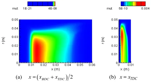
The contour of the turbulent viscosity, µt for a single compression process
with the piston velocity of up = -10 m/s are plotted in Fig. 2. Fig. 2 (a) is
the result at t = 0.01s during the single compression process, corresponding piston location isx=(xBDC+xTDC) / 2. Only the result for the cylinder diameter of D = 0.10 m is shown in the figure, but similar results are obtained for the cases of D = 0.01, 0.02, 0.04, 0.06 and 0.08 m. Fig. 2(b) is the result when the piston just reaches the TDC. Fig. 3 shows the maximum value of the turbulent viscosity as a function of piston location during the single compression process. As seen in Fig. 3, the maximum value of the turbulent viscosity in the cylinder for the cases of D≤ 0.04 m were less than the dynamic viscosity, µ (1.862×10⁻⁵ Pa.s)
when the piston was located atx=(xBDC+xTDC) / 2. Whereas for the cases of D≥ 0.06 m, the turbulent viscosity was higher than the dynamic viscosity when the piston was located at x=(xBDC+xTDC) / 2 . The maximum value of the turbulent viscosity for the cases of D≤ 0.04 m became almost 102 times larger than the dynamic viscosity at the center
of the squish area after the piston stopped at the TDC. The effect of the cylinder diameter on the turbulent viscosity is observed.
(a) x=
(
xBDC+xTDC)
2 (b) x=xTDCFig . 2 Contour of turbulent viscosity, µt for single compression process
with piston velocity of up= -10 m/s
The pressures and temperatures at the final state of the single compression process, pf and Tf , with the piston velocity,upof -10
m/s are listed in Table 1.pf and Tfobtained by the laminar computation
for all cases are also listed in Table 1. Note that they are almost identical to each other. Therefore, the flow can be considered laminar during a single compression process for all cases of different diameter although the turbulent viscosity in the core region is higher than the dynamic viscosity in the later stage of the compression process (also see Fig. 2 (b)). This phenomenon occurred since the process is in unsteady state and time dependence. The effect of the cylinder diameter on the state variables at the final state of the single compression is not observed.
Fig . 3 µt,maxvariations as a function of piston location( /x xTDC)for
3 The effect of the cylinder diameter on the pressure and temperature for the compression process are investigated for a piston velocity of -10 m/s. As mention in our previous studies (Yusof et al., 2018a and 2019), the pressure of a reversible adiabatic process, prev and the specific
volume, v* is related by
*
* i
rev i
v
p p
v γ
=
(2)
where γ is the specific heat ratio, γ = cp /cv, pi and vi* are the pressure and
the specific volume at the initial state.
Table 1 Pressure and temperature at final state for various cylinder diameters.
Cylinder diameterD
Laminar computation Turbulent computation
f
p (MPa) Tf (K) pf (MPa) Tf (K)
0.01 m 2.90851 783.049 2.90851 783.049
0.02 m 2.90851 783.049 2.90851 783.049
0.04 m 2.90852 783.051 2.90852 783.052
0.06 m 2.90851 783.051 2.90852 783.054
0.08 m 2.90852 783.053 2.90853 783.055
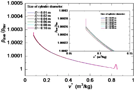
0.10 m 2.90852 783.052 2.90852 783.054 The ratios of the average pressure defined by Eq. (1) to the pressure of the reversible adiabatic process,pave/prev of the single compression
process are plotted in Fig. 4. As can be seen in the figure, the pressure ratiopave/previs greater than unity during the single compression for all
cases of diameters. An enlarged view of this pressure ratio, pave/prev
from the area of the blue circle also plotted in Fig. 4. The effect of the cylinder diameter on pave/previs slight. However, the pressure ratio
/
ave rev
p p slightly increases with increasing the cylinder diameter.
Fig . 4 Pressure ratios,pave/prev vs v∗ for various cylinder diameter
The ratio of the final pressure to the pressure of the reversible adiabatic process and the ratio of the final temperature to the temperature of the reversible adiabatic process at the final state, pf/pf rev, and
,
/
f f rev
T T obtained for the different cylinder diameter are almost identical
for all cases. The difference for both ratios,pf /pf rev, andTf/Tf rev, are
very small. Note that the pressure and temperature at the final states for all cases are almost identical (see Table 1).
The ratio of work done by the piston under the irreversible process to the work under the reversible process is plotted as the function of the
cylinder diameter in Fig. 5. The work ratio is greater than unity. These results indicate that the compression work done by the piston to the fluid under the irreversible process is greater than that in the reversible process. It was noting that when the process is adiabatic, thus the work ratio,
/ rev
w w is equal to the integration of −pave/prev from xBDC to
TDC
x . The internal energy at the final state of the irreversible process is
greater than the internal energy of the reversible process.∆i/ (− ×w) 100is also plotted in Fig. 5, where ∆i is the difference of the internal energies at the final state between the irreversible and reversible of the single compression process and (-w) is the single compression work. As seen from figure, 0.0413 % to 0.0424 % of the compression work irreversibly changes into the internal energy when the cylinder diameter increased from D = 0.01 m to 0.08 m. Bothw w/ revand ∆i/ (−w)of D = 0.10 m are
slightly lower than those of D = 0.08 m.
Fig . 5 w w/ rev and ∆i/ (− ×w) 100 vs up
3.2
Cyclic Compression and Expansion Processes using LB1S
Turbulence Model
The computations were performed for cyclic processes with sinusoidal velocity variation which is expressed by
(
)
60 30
p BDC TDC i
N N
u = − x −x π cosπ t+θ
(3)
where N is revolution number per minutes and θiis the crank angle from
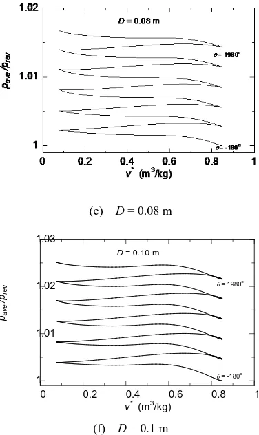
the TDC at t = 0. The selected value for the revolution number per minute is fixed at 20000 rpm. The effect of the cylinder diameter on the average pressure inside the cylinder is investigated for the range of D = 0.01 m to the D = 0.10 m. The ratio of the average pressure defined by Eq. (1) to the pressure of the reversible adiabatic process, pave/prev for 6 completed cyclic processes with sinusoidal velocity variation expressed by Eq. (3) is plotted in Fig. 6 (a) to (f) as a function of the specific volume,
v for the cases of D = 0.01 m to 0.10 m, respectively. As can be seen in the figures, the pressure ratio,pave/prev is greater than unity for all 6
completed cyclic processes. The value of pave/prev at the end of the
first cycle for all cases of D = 0.01 m to 0.10 m ranges from 1.00023 to 1.00462, respectively and increases in every cycle for all cases. The effect of the cylinder diameter on the ratio of the pressures is observed.
As we mentioned in our previous paper (Yusof et al., 2019), when the piston moves with higher rotation speed and it results in an increase of pave/prev compared to the piston moves with lower rotation speed. This is because, when the piston rotation speed increases, the velocity gradient also increases. In this case, increase the cylinder diameter also contributes to the increases of the internal energy due to the increases of viscous heat generation.
0 0.02 0.04 0.06 0.08 0.1
1.0004 1.00041 1.00042 1.00043
0.04 0.041 0.042 0.043
w / wrev
{ ∆i / (-w)}x (%)
D = 0.01 m D = 0.02 m
D = 0.04 m D = 0.06 m
D = 0.08 m
D = 0.10 m
{
∆
i /
(
-w
)}
x
(%
)
w /
w
re
v
4
(a)D = 0.01 m
(b)D = 0.02 m
(c)D = 0.04 m
(d)D = 0.06 m
(e) D = 0.08 m
(f) D = 0.1 m
Fig . 6 Pressure ratios, pave/prev of cyclic processes for various
cylinder diameters
Fig . 7 /
( )
BDC
x
i w
∆ − for 6 cycles of cyclic process (N=20000 rpm)
The ratio of ∆i to the compression work done by the piston to the fluid,
{
/( )
}
BDC x
i w
∆ − of the cyclic compression and expansion processes
are plotted in Fig. 7 as a function of cycle. As can be seen from the figure,
( )
{
/}
BDC x
i w
∆ − increases with increase of cycles. As seen from this figure,
for the cases of D = 0.01 m to 0.10 m, 0.060 % to 0.123 % of the compression work in each cycle is used for the deviation of the internal energy when the piston moved with sinusoidal velocity variation for the different cylinder diameter. These values are the average of 6 cycles. This means that increasing the cylinder diameter also contributes to the increases of the conversion of the compression work into thermal energy.
0 0.2 0.4 0.6 0.8 1
1 1.001 1.002
θ = -180o
θ = 1980o
D = 0.01 m
pav
e
/pre
v
v* (m3/kg)
0 0.2 0.4 0.6 0.8 1
1 1.001 1.002 1.003 1.004 1.005
D = 0.02 m
pav
e
/pre
v
v* (m3/kg)
θ = 1980o
θ = -180o
0 0.2 0.4 0.6 0.8 1
1 1.005 1.01
θ = -180o
θ = 1980o
D = 0.04 m
pav
e
/pre
v
v* (m3/kg)
0 0.2 0.4 0.6 0.8 1
1 1.01 1.02
θ = -180o
θ = 1980o
D = 0.06 m
pav
e
/pre
v
v* (m3/kg)
0 0.2 0.4 0.6 0.8 1
1 1.01 1.02 1.03
θ = -180o
θ = 1980o
D = 0.10 m
pav
e
/pre
v
v* (m3/kg)
0 1 2 3 4 5 6
0 0.002 0.004 0.006 0.008 0.01
Size of cylinder diameter:
D = 0.01 m
D = 0.02 m
D = 0.04 m
D = 0.06 m
D = 0.08 m
D = 0.10 m
{
∆
i /
(
-w
)} x
B
DC
5
4.
CONCLUSIONS
In this paper, effect of the cylinder diameter on the state quantities of the irreversible processes in the piston-cylinder system has been analyzed using ICED-ALE method. The following conclusions are obtained.
1. In the single compression process, 0.0413 % to 0.0424 % of the compression work irreversibly changes into the internal energy when the cylinder diameter increased from D = 0.01 m to 0.10 m. However, the effect of the cylinder diameter on the state quantities of the irreversible processes is very slight. 2. For the cyclic compression and expansion process, the value of
/
ave rev
p p at the end of the first cycle for all cases of D = 0.01 m to 0.10 m are about 1.00023 to 1.00462, respectively and increases in every cycle for all cases. The effect of the cylinder diameter on the state quantities of the irreversible processes linearly increases with increasing the cylinder diameter.
ACKNOWLEDGEMENTS
The authors would like to express their appreciation to University Technology Malaysia and Takasago Thermal Engineering Co, Ltd., Japan, for providing financial support for this work through Takasago education and research grant (Vote No: R. K130000.7343.4B365).
NOMENCLATURE
Cp constant pressure specific heat (J/kg⋅K)
D cylinder diameter (m)
i specific internal energy (J/kg)
m mass in cylinder (kg)
n polytropic index or rotation number -
p pressure (Pa)
R gas constant (J/kg⋅K)
T temperature (K)
t time (s)
u, v velocity components (m/s)
v* specific volume (m3/kg)
V volume of cylinder (m3)
r, x coordinates (m)
w specific work (J/kg)
Greek Symbols
γ specific heat ratio
λ thermal conductivity (W/m⋅K)
µ viscosity (Pa s)
θ crank angle (rad or deg)
ρ density (kg/m3) τ shear stress (Pa)
Subscripts ave average
BDC bottom dead center
f final
i initial
max maximum
ps piston surface
rev reversible
TDC top dead center
t turbulent
REFERENCES
Hirt, C.W., Amsden, A.A. and Cook, J.L., 1974, “An Arbitrary Lagrangian-Eulerian Computing Method for All Flow Speeds”, Journal of Computational Physics, 14(3), 227-253.
https://doi.org/10.1016/0021-9991(74)90051-5
Shabgard, H. and Faghri, A., 2019, “Exergy Analysis in Energy Systems: Fundamentals and Application”, Frontiers in Heat and Mass Transfer, 12(9), 1-16.
http://dx.doi.org/10.5098/hmt.12.9
Yusof, S. N. A., Asako, Y., Fahgri, M., Tan, L. K. and Sidik, N. A. C., 2018a, “Numerical Analysis for Irreversible Processes in a Piston-Cylinder System”, Int. J. Heat Mass Transfer, 124, 1097-1106. https://doi.org/10.1016/j.ijheatmasstransfer.2018.04.008
Yusof, S. N. A., Asako, Y., Tan, L. K. and Sidik, N. A. C., 2018b, “Piston Surface Pressure of Piston-Cylinder System with Finite Piston Speed”,
Journal of Advanced Research in Fluid Mechanics and Thermal Sciences, 44 (1), 55-65.
Yusof, S. N. A., Asako, Y., Fahgri, M., Tan, L. K. and Sidik, N. A. C., 2019, “Numerical Analysis of Irreversible Processes in a Piston-Cylinder System using LB1S Turbulence Model”, Int. J. Heat Mass Transfer, 136, 730-739.
https://doi.org/10.1016/j.ijheatmasstransfer.2019.03.007