INTRODUCTION
Future trends in the area of a robot industrial application are directed to building workplaces intended for different levels of a human-robot collaboration. This fact results from demands of an industrial practice to achieve the highest pos-sible flexibility of a production system to accom-modate to product production change quickly. Utilisation of a synergy of robot properties (pre-cision, repeatability, force) and human´s intel-ligence, flexibility and skill has its justification especially in the case of a small-scale production, where a flexible re-configuration of production system is a big advantage. The main problem of human-robot collaboration (HRC) is a safety of employees within a shared workspace. Solv-ing of this problem is a subject of nowadays re-search activities of the worldwide rere-search and development workplaces and also it follows the project Industry 4.0 vision. The research activi-ties are focused on development of multi-level sensor systems and intelligent software that allow industrial robot to be able to detect a human pres-ence in monitored zone in a timely manner and to adapt its activity to a level of a common
col-laborative space distortion by a human. Different vision-based approaches are applied for detecting a human´s entire silhouette and/or human body´s significant parts (head, limbs). Machine and com-puter vision systems play there an important role. The application of suitable vision technology de-pends on requirements of the target application. In the case of light-weight robots it is possible to use sensors, such as: cameras, lasers, Microsoft Kinect devices, and so on [27].
The means of computer aid are effective tool used within the process of robotized workcell de-signing. Their utilisation enables a shortening the time needed for a workcell design and its enter-ing into a production plant. Implementation of the first collaborative robots into production plants causes an increasing of demands put on a col-laborative workcell design. The main problem is that there a human and robot collaborate within a shared common workspace to perform the intend-ed tasks [12, 23, 24]. The presence of a human near an industrial robot is an increased safety risk. The recommendations related to reduction of this type of risks are listed in international standards and technical specifications [8, 10]. The result safety level of a collaborative robotized
work-UTILISATION OF KINECT SENSORS FOR THE DESIGN OF A HUMAN-ROBOT
COLLABORATIVE WORKCELL
Darina Kumičáková1, Alexander Rengevič1, Miroslav Císar1, Vladimír Tlach1
1 University of Žilina, Faculty of Mechanical Engineering, Department of Automation and Production Systems, Univerzitná 8215/1, 010 26 Žilina, Slovak Republic, e-mail: [email protected], [email protected]
Research Journal
Volume 11, Issue 4, December 2017, pages 270–278
DOI: 10.12913/22998624/80937 Research Article
ABSTRACT
The paper deals with a present topic of utilisation of nonconventional sensors for solv-ing the tasks of a human-robot collaboration within a shared workcell. The attention is primary focused on an exploring of possibilities of utilisation of low-cost Kinect sensors. The paper presents the methodical steps of solution of a sensor subsystem proposal within conditions of the laboratory robotised workcell, methods applied for the sensors intrinsic parameters calibration and their verification.
Keywords: Robotized workcell, Kinect sensor, Calibration, ROS Received: 2017.10.28
cell is given by used safety elements and the way of their controlling [3]. Design of collaborative robotized workcell requires an utilisation of in-novative technologies consisting of functions that allow a robot to sense a position of objects in its surroundings in real time [5, 17, 18]. The different types of 3D camera systems are used for examin-ing a position and identification of objects freely moving in 3D space in the area of robotic systems [1, 6]. The current market offers many types of 3D camera systems. The most affordable solu-tions are RGB-D sensors, as follows: Microsoft Kinect or Asus Xtion Pro Live. Kinect devices for its low start-up costs are often used in numerous research projects [7, 13, 16, 20]. Their utilisation for solving the problem of a human-worker cap-turing within the monitored space of the collab-orative workcell are described in [2, 29].
To achieve a high-quality image data ob-tained from RGB-D sensors for subsequent pro-cessing by the computer vision tools it is recom-mended to perform a calibration process [15, 19]. Used calibration method and conditions at which a calibration was performed have influence on a calibration process outcome.
The paper presents our approach to the design of collaborative workcell designed for exploring the possibilities of the robot Fanuc safe control with utilisation open-source platform ROS and Kinect devices within the laboratory conditions. The aim of this paper is to highlight the influence of properties of RGB-D sensors on the safety sys-tem developed proposal.
MOTIVATION
To ensure safety at the collaborative robot workcell, authors proposed the safety system whose structure is shown in Fig. 1. Safety sys-tem consists of three safety levels. Each of them uses its own rgb-d sensor. The roles of rgb-d sen-sors within a single safety levels are different. The rgb-d sensor intended for the first safety level detects big moving objects, i.e. human or mobile robotic arm, that are present in the monitored col-laborative space. The rgb-d sensor intended for the second safety level detects static and dynamic small or medium objects, i.e. parts, with which the human manipulates. The parts can be placed on the work desk in the different positions. The sensor intended for the third safety level senses and identifies the big objects moving within the wider surroundings of the collaborative space.
The safety system proposed for solving a human-robot safe collaboration was based on uti-lization of the Robotic Operating System (ROS). The reason for this decision was its openness on area of development of the new robotic applica-tions through integration of knowledge of a ro-bot controlling, computer vision, collision states solutions, etc. Open-source platform ROS offers the database of partial packages that accelerate and simplify a design and creation of new cus-tom robotic applications. There is also important the mention about the open-source project ROS-Industrial that covers activities related to extend-ing advanced capabilities of ROS for industrial applications, including area of industrial robotics [4, 21]. Our aim is create a method that allows designing of different kinds of collaborative ro-botic workcell using the Kinect sensor and Robot Operating System.
ANALYSIS OF THE POSSIBILITY OF USING
THE KINECT DEVICE
Description of Microsoft Kinect device
to their frame-rate, hardware demands and their compatibility within the proposed safety system functional structure. On the basis of the testing results we select Kinect Xbox 360 for further test-ing the safety system. Specification of this one is shown in Table. 1
Determination of the device operating parameters
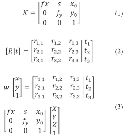
Operating parameters of cameras are divided into three groups: intrinsic parameters, extrinsic parameters and distortion coefficients. The in-trinsic parameters include: Focal Length (fx, fy), Focal Centre (x0, y0) and Skew Coefficients (s). Matrix of intrinsic parameters is expressed by re-lation (1). Extrinsic parameters represent the lo-cation of a camera in the real scene. Matrix of extrinsic parameters consists of rotation matrix R and translation vector t. They are expressed by relation (2). Interdependence between intrinsic and extrinsic parameters is expressed by relation (3). This relation is based on ideal pinhole camera model which represent ideal camera without lens. This means that ideal camera has no distortion. In relation (3) w is the scale factor; x, y are coordi-nates of the projection point in pixels; X, Y, Z are coordinates of 3D point in the world coordinate space. [14, 24, 28]
𝐾𝐾 = [
𝑓𝑓𝑓𝑓 𝑠𝑠 𝑓𝑓
0 𝑓𝑓
𝑦𝑦𝑦𝑦0
00
0
1
]
(1)[𝑅𝑅|𝑡𝑡] = [
𝑟𝑟
𝑟𝑟
1,12,1𝑟𝑟
𝑟𝑟
1,22,2𝑟𝑟
𝑟𝑟
1,32,3𝑟𝑟
3,1𝑟𝑟
3,2𝑟𝑟
3,3|
𝑡𝑡
𝑡𝑡
12𝑡𝑡
3]
(2)𝑤𝑤 [
𝑥𝑥
𝑦𝑦
1
] = [
𝑟𝑟
1,1𝑟𝑟
1,2𝑟𝑟
1,3𝑟𝑟
2,1𝑟𝑟
2,2𝑟𝑟
2,3𝑟𝑟
3,1𝑟𝑟
3,2𝑟𝑟
3,3|
𝑡𝑡
𝑡𝑡
12𝑡𝑡
3]
[
𝑓𝑓𝑥𝑥 𝑠𝑠 𝑥𝑥
0 𝑓𝑓
𝑦𝑦𝑦𝑦
000
0
1
] [
𝑋𝑋
𝑌𝑌
𝑍𝑍
1
]
(3)
Expressions of imperfection of real cameras are given by radial and tangential distortion. For radial factor correction are applied relations:
𝑥𝑥𝑜𝑜𝑜𝑜𝑜𝑜𝑜𝑜𝑜𝑜𝑜𝑜𝑜𝑜𝑜𝑜 = 𝑥𝑥 . (1 + 𝑘𝑘1 . 𝑟𝑟2+ 𝑘𝑘2. 𝑟𝑟4+ 𝑘𝑘2. 𝑟𝑟6) (4)
𝑦𝑦𝑐𝑐𝑐𝑐𝑐𝑐𝑐𝑐𝑐𝑐𝑐𝑐𝑐𝑐𝑐𝑐𝑐𝑐= 𝑦𝑦 . (1 + 𝑘𝑘1 . 𝑟𝑟2+ 𝑘𝑘2. 𝑟𝑟4+ 𝑘𝑘2. 𝑟𝑟6) (5)
For tangential factor correction are applied relations:
𝑥𝑥𝑐𝑐𝑐𝑐𝑐𝑐𝑐𝑐𝑐𝑐𝑐𝑐𝑐𝑐𝑐𝑐𝑐𝑐= 𝑥𝑥 + [2 . 𝑝𝑝1 . 𝑥𝑥𝑥𝑥 + 𝑝𝑝2 . (𝑟𝑟2+ 2𝑥𝑥2)] (6)
𝑦𝑦𝑐𝑐𝑐𝑐𝑐𝑐𝑐𝑐𝑐𝑐𝑐𝑐𝑐𝑐𝑐𝑐𝑐𝑐= 𝑦𝑦 + [𝑝𝑝1 . (𝑟𝑟2+ 2𝑦𝑦2) + 2𝑝𝑝2. 𝑥𝑥𝑦𝑦] (7)
Above relations take into account five distor-tion coefficients expressed by matrix D, where
k1, k2, k3 are radial distortion coefficients and p1, p2 are tangential distortion coefficients:
𝐷𝐷 = (𝑘𝑘
1𝑘𝑘
2𝑝𝑝
1𝑝𝑝
2𝑘𝑘
3)
(8)For determination of intrinsic parameters and distortion coefficients was used package for calibration of monocular cameras available on ROS websites [22]. Used calibration program is based on algorithms offered by OpenCV library. Detailed description of the algorithms is given on OpenCV websites [14]. Environment of the cali-bration program is shown in Fig. 3a. The layout of the calibration workplace is shown in Fig. 3b. The position of the calibrated device was not change during the calibration process. Its uniqueness was guaranteed by using a tripod. The calibration
pat-tern was fixed on the flat surface board that was kept by the industrial robot´s gripper. The robot´s manipulator ensures required movement of the calibration pattern in the space. Calibration mea-surements were carried out according to proce-dure prescribed by the package´s author. During the calibration process the multiple calibration patterns with checkboard patterns having square width of 20 mm, 25 mm, 30 mm and 108 mm were used. For calibration the pattern with 108 mm square size was used other calibration equip-ment because of its large size. The calibration pattern was mounted on the board with a smooth surface. This board was placed on a mobile car-riage and its measuring position in the workspace was ensured by a human. Calibration of IR-cam-era required disabling of IR-projector that creates light reflection on calibration pattern and makes the calibration impossible.
On the basis of the results of calibration of different types calibration patterns performed by two calibration techniques we can summarize ob-tained knowledge as follows:
• in generally, values determined bay calibra-tion donot differ more significantly,
Table 1 Technical parameters of device Microsoft Kinect Xbox 360 [Y13]
Sensing method Triangulation – Structured Light
RGB camera resolution 640 x 480 pixels at 30 Hz
IR camera 640 x 480 pixels
Max depth distance 3.5 m
Minimal depth distance 0,8 m
Horizontal FOV 57°
Vertical FOV 43°
Tilt motor Yes with actual tilt monitoring
Communication Bus USB 2.0
Price 80 €
a) b)
• utilisation of the robot Fanuc for ensuring a movement with the calibration patterns brought an advantage not only of reduction of number of calibration samples needed for cre-ation the final calibrcre-ation file but also a reduc-tion of this file computing time,
• use of the intrinsic calibration parameters was not significantly reflected on a sensed image quality,
• with increasing a square size of the calibra-tion pattern the distance at which the camera was able to recognize calibration pattern was enlarging.
Calibration files with values obtained from calibration processes of calibration patterns of both 20 mm and 108 mm square widths were se-lected for their utilisation within the real collab-orative workcell design. Table 2 and Table 3 show comparison of intrinsic parameters and distortion coefficients of the cameras. There the values of the first row represent the default calibration val-ues given by the device´s producer. The valval-ues of the second row represent the values obtained after calibration of the first Kinect device that is intended for capturing small objects placed on the table working plate. The values of the third row represent the calibration values used for the other
two Kinect devices that are intended for capturing larger objects like human or mobile robotic plat-form within the two monitored zones.
Creation of virtual representation of collaborative robotic workcell
For determination of the device´s extrinsic parameter it was necessary to create a virtual representation of a workcell. For this purpose the program Creo Parametric 2.0 was used. In the ro-botic workcell design we have taken into account the following factors:
• Detection range of the device (see Table 1). • Field of view of the device in horizontal and
vertical directions (see Table 1).
• Position of the industrial robot FANUC LR Mate 200iC within the workcell and also its workspace envelope.
• Human´s position intended within the collab-orative workspace.
On the basis of the Kinect device technical parameters specified by manufacturer (see Tab. 1) the virtual representation of its field of view was designed. Minimum, ideal and maximum ranges of field of view of the devices were distinguished by shades of grey and green colours (see Fig. 5).
Table 2. Comparison of calibration values of RGB-camera
Focal Length Focal Centre Skew
fx fy x0 y0 s
Default 525.000 525.000 319.500 239.500 0.000
20 mm 519.550 519.944 306.320 252.358 0.000
108 mm 521.039 521.712 306.422 250.812 0.000
Distortion coefficients
k1 k2 p1 p2 k3
Default 0.000 0.000 0.000 0.000 0.000
20 mm 0.153 - 0.268 0.002 0.001 0.000
108 mm 0.137 - 0.232 0.000 - 0.001 0.000
Table 3. Comparison of calibration values of IR-camera
Focal Length Focal Centre Skew
fx fy x0 y0 s
Default 575.816 575.816 314.500 235.500 0.000
20 mm 581.677 582.424 325.825 241.146 0.000
108 mm 577.891 568.122 325.449 240.890 0.000
Distortion coefficients
k1 k2 p1 p2 k3
Default 0.000 0.000 0.000 0.000 0.000
20 mm -0.071 0.124 0.001 0.003 0.000
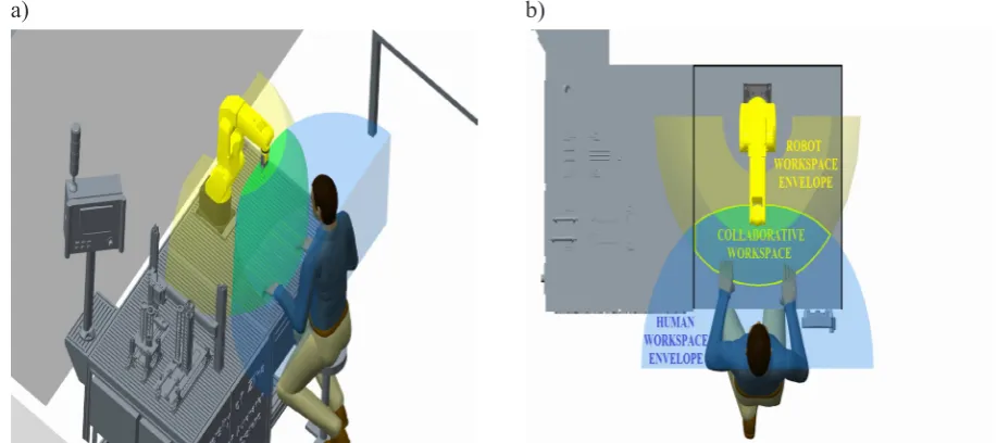
The boundaries of a human-robot collaborative workspace were established on the basis of an intersection of both human and robot workspace envelope surfaces and the upper plane of the table working plate. Workspace envelope for the in-dustrial robot was created in Creo Parametric 2.0 with using the simulation tools of its CAE module Mechanism. There was considered the maximum possible reach of the robot arm equipped with gripping effector oriented to grip the object in the direction perpendicular to the table working plate (see Fig. 4a). The robot kinematic model was created with using a limited range of motions in each of its joints, defined according to the robot technical specification. On the basis of the special kinematic link defined between the gripper´s TCP and the plane parallel to the table working plate and also specifically defined movement for the robot´s J1 and J3 axes it was possible to simulate movement of TCP point. The TCP point described the widening circles of graduated layers. Totally 12 layers in 50 mm distances were used. By fold-ing the end points and usfold-ing contour surface, we get the final shape of the robot workspace enve-lope. Human body was replaced by a mannequin in the simulation environment. [26]Working en-velope of the human was created on the basis of the data contained in the standards of workplace ergonomics [9]. A discrete area representing the established collaborative workspace is shown in Fig. 4b. Virtual models of the working table and the facilities placed within The Laboratory Work-place of Automated Assembly have been created based on dimensions of the real objects. A
com-puter-aided design of the collaborative robotized workcell including a preliminary draft of the sen-sors arrangement is shown in Fig. 5.
Placement of sensors at the real collaborative workcell
On the basis of both camera´s internal param-eters determined after the calibration processes and the created 3D model of collaborative work-cell it was possible to adjust the Kinect device´s extrinsic parameters. For this purpose it has been suggested some methodic steps, described below. A process of the extrinsic parameters calibra-tion was carried out with using the ROS´s visu-alizer tool Rviz. For the proper process of cali-bration was necessary to load all relevant nodes and properly configure RViz. This process was performed in four main steps. The first one repre-sented a creation of files that contain an initial ap-proximate position of Kinect devices in the global coordinate system. The point located in the inter-section of the robot´s joint axis J1 and the table working plate was defined as an imaginary centre of the virtual environment. This point represents the centre of so-called base coordinate system of a robot. The second step included an adding the physical models of the robot Fanuc and other facilities located at the workplace of automated assembly. In the third step, we launched com-munication with Kinect with necessary configu-ration parameters of OpenNI driver. Thus it was possible to observe data incoming from Kinect in Rviz. By selecting the data type required for
a) b)
the visualisation functions Depth Cloud or Point-Cloud, the system automatically displays images from Kinect device on a predefined location.
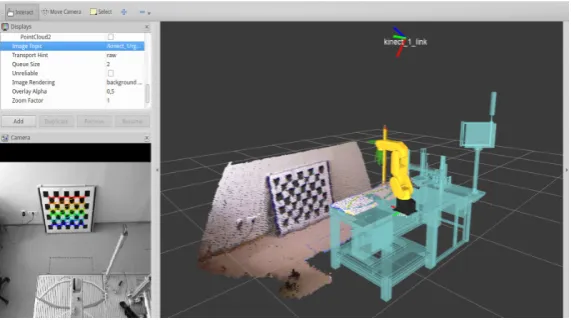
Thus it was possible visually compare the model representation of the table working plate with the real one that is sensed within the real workcell. The final step included a measurement of displacement between points of the model rep-resentation and their associated points in cloud. The differences between the points can be deter-mined by using RViz measure tool and adjusted by varying the value in the original file. Environ-ment of Rviz visualisation tool is shown in Fig. 6.
One of key parameters of the Kinect devices proper placement within the laboratory work-space is their recognition ability. On the basis of finding the dependence between the size of the calibration pattern and the recognition distance of Kinect device it was possible to identify the maximum distance for recognizing an object of required dimensions. Human body or a mobile
robotic device belongs to group of objects with larger dimensions. For purpose of their recog-nition in monitored zones the first and the third safety levels were defined. The distance between Kinect device and the plane on which lies the furthest recognizable point was defined by cali-bration pattern with 108 mm square width. For the second safety level where will be performed manipulation with the smaller parts, was used the same procedure with 20 mm square calibration pattern. Recognition of 20 mm square calibration pattern has not been possible in more distant im-age areas. Along with decreasing mounting height of device was reduced size of the monitored zone. In order to capture the whole area of collabora-tive workspace and recognize calibration pattern it was necessary to use 30 mm square calibration pattern. Observed maximum distances were taken into account in determining the best suitable posi-tion of each Kinect device. Proposed locaposi-tion of device for Safety Level 2 was not confirmed. To
Fig. 6. Kinect device´s extrinsic parameters calibration
a) b)
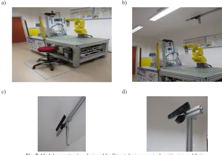
meet all specified requirements was device placed on the side of collaborative workspace (see Fig. 7a and 7b). Simple modular constructions were designed for adjusting and fixing the Kinect de-vices exact position – see Fig. 7c and 7d.
CONCLUSION
Created design of collaborative robotic work-cell is contemplated using of innovative ways of ensuring cooperating entities. To compensate im-perfections of the devices used to monitor subject behaviour was performed a set of calibration pro-cesses. On the basis of the results of performed measurements it was found that the use of dif-ferent sized calibration patterns affects the value of maximum distance in which the Kinect is still able to recognize the object. Insufficient resolu-tion capability of the used device significantly af-fects its usability within the intended application. Creating of the model representation of the col-laborative robotic workcell in the program Creo Parametric 2.0 and its transfer into the program Rviz allowed a verification of all settings of the Kinect devices needed for the future testing of the
proposed safety system. In further work we want to continue with creation of an automated system for extrinsic calibration process.
REFERENCES
1. AtonAton, LLC., Quipt – Taming industrial robot-ics. 2017. Available at: https://atonaton.com/quipt . 2. Beyl T., Nicolai P., Raczkowsky J.: Multi kinect
people detection for intuitive and safe human robot cooperation in the operating room. In: Proceed-ings of the 2013 IEEE International Conference on Advenced Robotics (ICAR), 2013, ISBN: 978–1-4799–2722–7.
3. Bolmsjo G., Bennulf M., Zhang X.: Safety System for Industrial Robots to Support Collaboration. In: Schlick C., Trzcieliński S. (eds) Advances in Ergo-nomics of Manufacturing: Managing the Enterprise of the Future. In: Advances in Intelligent Systems and Computing, vol. 490. Springer. Cham, 2016, ISBN 978–3-319–41697–7_23.
4. Edwards, S.M.: Ros Industial. Description. 2017 Available at: http://rosindustrial.org/about/descrip-tion/.
5. Elkmann, N.: Safe Human-Robot Cooperation with High Payloads Robots in Industrial
Applica-a) b)
c) d)
Fig. 7. Modular construction designed for Kinect devices required positioning and fixing;
tions (SAPARO), 2017. Available at: http://www. iff.fraunhofer.de/en/business-units/robotic-sys-tems/saparo.html.
6. Gannon, M., Mimus: Coming Face-to-Face With Our Companion Species. In “Fear And Love: Re-actions to a Complex World”. McGuirk, J., and Herrero, G, (eds.) Phaidon Press, Ltd. London, UK, 2016.
7. Gupta, S. K., Kaipa, K., Morato, C., Zhao, B.: En-suring Safety in Human Robot Collaboration in Assembly Applications. Maryland Robotic Cen-ter: The Institute for Systems Research. Avail-able on Internet: http://www.terpconnect.umd. edu/~skgupta/HRC.pdf.
8. ISO 10218–1:2006 Robots and robotic devic-es – Safety requirements of industrial robots – Part 1: Robots; 3.4.
9. ISO 6385:2004 Ergonomic principles in the design of work systems.
10. ISO/TS 15066:2016 Robots and robotic devices – Collaborative robots.
11. Krig S.: Computer Vision Metrics – Survey, Tax-onomy, and Analysis. Apress Media, LLC., 2014, ISBN: 978–1-4303–5929–9.
12. Kuric I., Popescu S., Brad S., Popescu D.: New methods and trends in product development and planing. In: Quality and Inovation in engineering and managment, Technical University Cluj-Nap-oca, 2011. ISBN: 978–973–662–614–2.
13. Materna Z., Kapinus M., Špaňel M., Beran V., Smrž P.: Simplified Industrial Robot Program-ming: Effects of Errors on Multimodal Interaction in WoZ experiment. In: 2016 25th IEEE Interna-tional Symposium on Robot and Human Interac-tive Communication (RO-MAN), 2016, pages 200–205. Electronic ISSN: 1944–9437.
14. OpenCV Dev. Team.: Camera Calibration and 3D Reconstruction, 2017. Available at: http://docs. opencv.org/2.4/modules/calib3d/doc/camera_cali-bration_and_3d_reconstruction.html.
15. [15] Pagliari, D. Pinto, L.: Calibration of Kinect for Xbox One and Comparison between the Two Generations of Microsoft Sensors. Sensors. 2015. ISSN 1424–8220.
16. Perzylo A., Somani N., Profanter S., Rickert M., Knoll A.: Multimodal binding of parameters for Task-based robot programming based on semantic descriptions of modalities and parameter types. In: CEUR Workshop Proceedings, Vol. 1540, 2015. Workshop on Multimodal Semantics for Robotic Systems. IEEE/RSJ International Conference on IROS, Hamburg, Germany, 2015 Pages 21–24. ISSN 16130073.
17. Piltz GmbH & Co.KG: Safe camera system Safe-tyEYE: Montioring and control with a single safe
camera system, 2017, Available at: https://www. pilz.com/en-GB/eshop/00106002207042/Safety-EYE-Safe-camera-system.
18. Poppeová, V., Uríček, J., Bulej, V., Havlas, P.: De-sign of ANTI-collision system for robotics. In: Ap-plied Mechanics and Materials, Vol. 327/ 2013. pp. 1071–1075. ISSN: 1660–9336.
19. Raposo C., Barreto J.P. Nunes U.:Fast and Ac-curate Calibration of a Kinect Sensor. In: Ad-vanced Concepts for Intelligent Vision Systems, 17th International Conference ACIVS. Springer International Publishing AG, 2016, ISBN: 978–3-319–488679–6.
20. Roitberg A., Somani N., Perzylo A., Rickert M., Knoll A.: Multimodal Human Activity Recogni-tion for Industrial Manufacturing Processes in Ro-botic Workcells. In: Proceeding of 17th ACM In-ternational Conference on Multimodal Interaction, Seattle, USA. Nov. 9–13th, 2015, pages 259–266, ISBN 978–1-4503–3912–4.
21. ROS: About ROS. 2017. Available at: http://www. ros.org/.
22. ROS: How to Calibrate a Monocular Camera. 2017. Available at: http://wiki.ros.org/camera_cali-bration/Tutorials/MonocularCalibration.
23. Sága, M., Vaško. M., Čuboňová, N.: Optimaliza-tion algorithms in mechnical engeneering appli-cations. In: Harlow: Pearson. 2016, ISBN 978–1-78449–135–2.
24. Siciliano B., Khatib O.: Springer Handbook of Robotics. Springer International Publishing, 2016, ISBN 978–3-319–32550–7.
25. Smisek J., Jancosek M, Pajdla T.: 3D with Kinect. In: Consumer Depth Cameras for Computer Vi-sion: Research Topics and Applications ,Springer, 2013, ISBN: 978–1-4471–4640–7_1.
26. Uricek, J., et al:: The Calculation of Inverse Kine-matic for 6DOF Serial Robot, Communications – Scientific Letters of the University of Zilina, ISSN 1335–4205, vol. 16, No. 3A, 2014, 154–160. 27. Vysocky A., Novak P.: Human-Robot
Collabora-tion in Industry. In: MM Science Journal. June 2016, p. 903–906, ISSN 1803–1269. Available on Internet: https://www.imveurope.com/feature/ collaborative-co-workers .
28. Zhang Z.: A Flexibile New Technique for Cam-era Calibration. In: IEEE Transactions on Pattern Analysis and Machine Intelligence, IEEE, ISSN: 0162–8828.
![Table 1 Technical parameters of device Microsoft Kinect Xbox 360 [Y13]](https://thumb-us.123doks.com/thumbv2/123dok_us/8807135.1775189/4.595.74.517.588.748/table-technical-parameters-device-microsoft-kinect-xbox-y.webp)