An Efficient Meta Heuristic Algorithm to Solve Economic
Load Dispatch Problems
R. Subramanian* (C.A.), K. Thanushkodi* and A. Prakash*
Abstract: The Economic Load Dispatch (ELD) problems in power generation systems are to reduce the fuel cost by reducing the total cost for the generation of electric power. This paper presents an efficient Modified Firefly Algorithm (MFA), for solving ELD Problem. The main objective of the problems is to minimize the total fuel cost of the generating units having quadratic cost functions subjected to limits on generator true power output and transmission losses. The MFA is a stochastic, Meta heuristic approach based on the idealized behaviour of the flashing characteristics of fireflies. This paper presents an application of MFA to ELD for 3,6,13 and 15 generator test case systems. MFA is applied to ELD problem and compared its solution quality and computation efficiency to Genetic Algorithm (GA), Differential Evolution (DE), Particle Swarm Optimization (PSO), Artificial Bee Colony optimization (ABC), Biogeography-Based Optimization (BBO), Bacterial Foraging Optimization (BFO), Firefly Algorithm (FA) techniques. The simulation result shows that the proposed algorithm outperforms previous optimization methods.
Keywords: Artificial Bee Colony Optimization, Biogeography-Based Optimization, Economic Load Dispatch, Firefly Algorithm, Genetic Algorithm, Particle Swarm Optimization.
1 Introduction1
Electrical power industry restructuring has created highly vibrant and competitive market that altered many aspects of the power industry. In this changed scenario, scarcity of energy resources, increasing power generation cost, environment concern, ever growing demand for electrical energy necessitate optimal dispatch.
Economic Load Dispatch (ELD) is one of the important optimization problems in power systems that have the objective of dividing the power demand among the online generators economically while satisfying various constraints. Since the cost of the power generation is exorbitant, an optimum dispatch saves a considerable amount of money.
Optimal generation dispatch is one of the most important problems in power system engineering, being a technique commonly used by operators in every day system operations. Optimal generation seeks to allocate the real and reactive power throughout power system obtaining optimal operating state that reduces cost and
Iranian Journal of Electrical & Electronic Engineering, 2013. Paper first received 11 Mar. 2013 and in revised form 19 Oct. 2013. * The Authors are with the Akshaya College of Engineering and Technology, Coimbatore, India.
E-mails: [email protected], [email protected] and [email protected].
improves overall system efficiency. The ELD problem reduces the system cost by allocating the real power among online generating units.
In the ELD problem the classical formulation presents deficiencies due to simplicity of models. Here, the power system modelled through the power balance equation and generators are modelled with smooth quadratic cost functions and generator output constraints, transmission loss constraints [1] and security constraints [2].
To improve power system studies, new models are continuously being developed that result in a more efficient system operations. Cost functions that consider valve point loadings, fuel switching, and prohibited operating zones as well as constraints that provide more accurate representation of system such as: emission, ramp rate limits, line flow limits, spinning reserve requirement and system voltage profile. The improved models generally increase the level of complexity of the optimization problem due to the non-linearity associated with them.
Traditional algorithms like lambda iteration, base point participation factor, gradient method, and Newton method can solve the ELD problems effectively if and only if the fuel-cost curves of the generating units are piece-wise linear and monotonically increasing. The basic ELD considers the power balance constraint apart
from the generating capacity limits. However, a practical ELD must take ramp rate limits, prohibited operating zones, valve point effects, and multi fuel options into consideration to provide the completeness for the ELD formulation. The resulting ELD is a non-convex optimization problem, which is a challenging one and cannot be solved by the traditional methods. Practical ELD problems have nonlinear, non-convex type objective function with intense equality and inequality constraints. Recent advances in computation and the search for better results of complex optimization problems have fomented the development of techniques known as Evolutionary Algorithms.
The methods for solving these kinds of problems include traditional mathematical programming such as linear programming, quadratic programming, dynamic programming, gradient methods, Lagrangian relaxation and conventional methods like Taguchi Method (TM) [3] and Gravitational Search Algorithm (GSA) [4] approaches and modern meta-heuristic methods such as Genetic Algorithms (GA) [5-7], Evolutionary Programming [8], Hop Field Neural Network (HNN) [9], Particle Swarm Optimization (PSO) [10-13], Bacterial Foraging Optimization (BFO) [14], Artificial Bee Colony (ABC) [15], Differential Evolution (DE) [16] and Biogeography-Based Optimization (BBO) [17] are some of these methods which are successful in locating the optimal solution but they are usually slow in convergence.
2 Problem Formulation
The classical ELD problem is an optimization problem that determines the power output of each online generator that will result in a least cost system operating state. The objective of the classical economic dispatch is to minimize the total system cost where the total system cost is a function composed by the sum of the cost functions of each generator. This power allocation is done considering system balance between generation and loads, and feasible regions of operation for each generating unit.
The Economic dispatch problem is a fuel cost minimization of problem when several generators are operated to meet the required power demand. The objective function is given by:
( ) 1
t i i
n
MinimizeF F P
i = ∑
= (1)
where Ft is total fuel cost in $/h, Pi is the power output of ith Generator in MW and F
i (Pi )is the fuel cost equation of the ‘i’th plant expressed as follows.
∑
= + +
= n
i aiPi biPi ci
) P (
Fi i
1
2 (2)
where ai, bi and ci are the fuel cost coefficients of ith Generator in $/MW2 h, $/MWh, and $/h respectively.
The total fuel cost to be minimized is subject to the following constraints.
l d
i P P
n
i P
+ ∑
=1 = (3)
where Pd and Pl are the system power demand and power loss in MW respectively.
The system power loss is given by the relation:
00
1 1 1
0 P B
B P
B P P
n
i n
j
n
i i i j
ij i
L =
∑∑
+∑
+= = =
(4)
where B and Bo are the loss coefficient matrices and Boo is the loss coefficient constant.
The inequality constraint is given by
max i i min
i P P
P ≤ ≤ (5)
where Pimin and Pimax are the minimum and maximum generation limit of ith Generator in MW respectively.
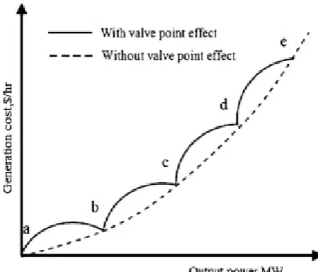
2.1 Valve Point Loading Effects
The valve-point loading effect has been modelled as a recurring rectified sinusoidal function, such as the one shown in Fig. 1 and Eq. (6) represents fuel cost including valve point loading.
)) P P ( f sin( e c P b P a ) (P
Fi i = i i2+ i i + i+ i i imin− i (6)
2.2 Ramp Rate Limit Constraints
In ELD studies, the unit generation output is usually assumed to be adjusted instantaneously. Even though this assumption simplifies the problem, it does not reflect the actual operating processes of the generating unit. Therefore, in practical situations, the operating range of all online units is restricted by their ramp rate limits, for forcing the units operation continually between two adjacent specific periods.
The inequality constraints due to ramp rate limits are given by:
Fig. 1 operating cost characteristics with valve point loading.
¾ if generation increases,
i i
i P UR
P − 0 ≤ (7)
¾ if generation decreases,
i i 0
i P DR
P − ≤ (8)
where Pi and Pi0 are the current and previous power output of unit i, respectively. URi and DRi are the up and down ramp rate limit of the i-th generating unit (in MW/h), respectively.
2.3 Prohibited Operating Zones (POZ) Prohibited Operating Zones (POZ) in the input-output curve of generator are due to steam valve operation or vibration in its shaft bearing. In practice, it is difficult to determine the prohibited zone by actual performance testing or operating records. In actual operation, the best economy is achieved by avoiding operation in these areas. Hence, the feasible operation zone of unit i can be given as follows:
min
i ,1
U
i,k-1 ,
U max
i,nz P
P 1...
P
L
i i
L i i k
i i
P P
P P k nz
P P
⎫
≤ ≤
⎪⎪
≤ ≤ ⎬ =
⎪
≤ ≤ ⎪⎭
(9)
3 The Firefly Algorithm
The Firefly Algorithm (FA) [18-20], is a Meta heuristic, nature-inspired, optimization algorithm which is based on the social flashing behavior of fireflies, or lighting bugs, in the summer sky in the tropical temperature regions. It was developed by Dr. Xin-She Yang at Cambridge University in 2007, and it is based on the swarm behavior such as fish, insects, or bird schooling in nature. In particular, although the firefly algorithm has many similarities with other algorithms which are based on the so-called swarm intelligence, such as the famous Particle Swarm Optimization, and Artificial Bee Colony optimization algorithms it is indeed much simpler both in concept and implementation. The main advantage is that it uses mainly real random numbers, and it is based on the global communication among the swarm particles [i.e., the fireflies], and as a result, it seems more effective in optimization such as the ELD problem in our case.
The FA has three particular idealized rules. They are • All fireflies are unisex, and they will move
towards more attractive and brighter ones regardless their sex.
• The degree of attractiveness of a firefly is proportional to its brightness which decreases as the distance from the other firefly increases due to the fact that the air absorbs light. If there is not a brighter or more attractive firefly than a particular one, it will then move randomly. • The brightness or light intensity of a firefly is
determined by the value of the objective function of a given problem. For maximization
problems, the light intensity is proportional to the value of the objective function.
3.1 Algorithm
Step 1: Read the system data such as cost coefficients, minimum and maximum power limits of all generator units, power demand and B-coefficients.
Step 2: Initialize the parameters and constants of Firefly Algorithm. They are noff, αmax, αmin, β0, γmin,
γmaxand itermax (maximum number of iterations).
Step 3: Generate noff number of fireflies randomly between λminand λmax.
Step 4: Set iteration count to 1.
Step 5: Calculate the fitness values corresponding to noff number of fireflies.
Step 6: Obtain the best fitness value GbestFV by comparing all the fitness values and also obtain the best firefly values GbestFF corresponding to the best fitness value GbestFV.
Step 7: Determine alpha (α) value of current iteration using the following equation: α (iter) = αmax - ((αmax - αmin) (current Iteration number)/ itermax)
Step 8: Determine the rij values of each firefly using the following equation: rij= GbestFV -FV rij is obtained by finding the difference between the best fitness value GbestFV (GbestFV is the best fitness value i.e., jth firefly) and fitness value FV of the ith firefly.
Step 9: New xi values are calculated for all the fireflies using the following equation:
2
i new 0
X *exp( . *( )
1
( ) *( )
2
iold ij j i
X r x x
iter rand
β γ
α
= + − −
− − (10)
In Eq. (10), β0 is the initial attractiveness γ is the absorption co-efficient rij is the difference between the best fitness value GbestFV and fitness value FV of the ith firefly. α(iter) is the randomization parameter ( In this work, α (iter) is set to 0.2) rand is the random number between 0 and 1.In this work, x →λ.
Step 10: Iteration count is incremented and if iteration count is not reached maximum then go to step 5.
Step 11:GbestFF gives the optimal solution of the Economic Load Dispatch problem and the results are printed.
The basic steps of the FA can be summarized as the pseudo code for Firefly Algorithm as follows.
3.2 Pseudo Code for Firefly Algorithm
• Objective function f(x), x = (x1,…,xd)T
• Generate initial population of fireflies xi (i=1, 2.., n) • Light intensity Ii at xi is determined by f(xi)
• Define light absorption coefficient γ
• while (t < MaxGeneration) • for i = 1: n all n fireflies
• for j = 1: i all n fireflies if (Ij > Ii), More firefly i towards j in d-dimension; end if
• Attractiveness varies with distance r via exp [-γr] • Evaluate new solutions and update light intensity. • end for j
• end for i
• Rank the fireflies and find the current best. • end while
• Post process results and visualization.
4 Modified Firefly Algorithm
The Modified Firefly Algorithm (MFA) was proposed in this paper to improve the exploration of the searching optimum solution. Two modifications have been done. Firstly, instead of using Cartesian distance of rij, the modification was done by finding the minimum variation distance between fireflies i and secondly, to improve the exploration or diversity of the candidate of solution, the simple mutation corresponds to α is adopted in the FA process. Thus it will enhance the optimum results in solving ELD. The proposed modifications can be summarized as the pseudo code given below.
4.1 Constraint Handling in MFA
A significant factor in the application of optimization techniques is how the algorithm handles the constraints concerning the problem. The POZ constraints Eq. (9) are utilized as follows. If the generation of ith unit is settled in its jth POZ, i.e.:
UB j , i i LB
j ,
i P P
P ≤ ≤ (11)
Then the amount of generation is cut to the nearest boundary of the jth POZ as follows:
⎟ ⎟ ⎠ ⎞ ⎜
⎜ ⎝
⎛ +
=
2
UB j , i LB
j , i LB
j , i
P P
P (12)
, , ,
, , ,
LB LB ave
i i j i j i i j
UB ave UB
i j i j i i j
P P ifP P P
P ifP P P
⎫
= ∠ ≤ ⎪
⎬
∠ ≤ ⎪⎭ (13)
For a nonlinear optimization problem with equality and inequality constraints, a common method is the penalty method. The idea is to define a penalty function so that the constrained problem is transformed into an unconstrained problem. Now we can define:
∏
∑
∑
= =
+ +
= M
i
N
i j j i
i j
,
i ) f(x) (x) (x)
, x (
1 1
2
2 ν ψ
φ μ ν
μ (14)
where μj≥ 1 and vj ≥ 0 which should be large enough, depending on the solution quality needed. As we can see, when an equality constraint it met, its effect or contribution to Π is zero. However, when it is violated, it is penalized heavily as it increases Π significantly. Similarly, it is true when inequality constraints becomes tight or exactly. It should be mentioned that generation and ramp rate limits are similar type of constraints.
These constraints together state the overall upper/lower generation limits of the units.
4.2 Pseudo Code for MFA
• Objective function f(x) x = (x1,…,xd)T
• Generate initial population of fireflies xi (i=1, 2…, n)
• Light intensity Ii at xi is determined by f (xi) • Define light absorption coefficient γ • while (t < MaxGeneration)
• for i = 1: n all n fireflies • for j = 1: i all n fireflies
• if (Ij > Ii), More firefly i towards j in d-dimension; end if
• Find the minimum variation distance of all • fireflies r = min((firefly i –firefly j))
• Attractiveness varies with distance r via exp[-γr] Evaluate new solutions and update light intensity • end for j
• end for i • randnum
• Mutation if randnum < probability of mutation • Rank the fireflies and find the current best • end while
• Post process results and visualization.
5 Simulation Results
To solve the ELD problem, the MFA is coded with MATLAB programming and it was run on a computer with an Intel Core2 Duo processor, windows operating system. Mathematical calculations and comparisons can be done very quickly and effectively with MATLAB.
Since the performance of the proposed algorithm sometimes depends on input parameters, they should be carefully chosen. After several runs, the following input control parameters are found to be best for optimal performance of the proposed algorithm.
In this proposed method, we represent and associate each firefly with a valid power output (i.e., potential solution) encoded as a real number for each power generator unit, while the fuel cost objective i.e., the objective function of the problem is associated and represented by the light intensity of the fireflies.
In this simulation, the values of the control parameters are: α = 0.2, γ=1.0, β0 = 1.0 and n =12, and the maximum generation of fireflies (iterations) is 100. The values of the fuel cost, the power limits of each generator, the power loss coefficients, and the total power load demand are supplied as inputs to the firefly algorithm.
The power output of each generator, the total system power, the fuel cost with transmission losses are considered as outputs of the proposed MFA algorithm. Initially, the objective function of the given problem is formulated and it is associated with the light intensity of the swarm of the fireflies.
The MFA has been proposed for 3, 6, 13 and 15 machine IEEE standard test systems. The proposed MFA method has been compared with various optimization methods and is tabulated from Tables 1 to 4. According to the result obtained, the MFA for ELD is more advantageous than all other Algorithms. From the simulation results of 3, 6, 13 and 15 generator test system for ELD using MFA method, the total fuel cost and total line losses are decreased than all other algorithms.
6 Conclusion
The proposed MFA to solve ELD problem by considering the practical constraints has been presented in this paper. From the comparison table it is observed that the proposed algorithm exhibits a better performance with respect to all other techniques. The effectiveness of MFA was demonstrated and tested in this research. From the simulations, it can be seen that MFA gave the best result of total cost minimization compared to all other optimization methods. In future, the proposed MFA can be used to solve ELD considering the valve point loading effects.
Table 1 Comparison table for 3- unit system (Pd=850 MW) with valve point loading effects.
S.
No Description
GA [5]
PSO
[11] MFA
1. P1 (MW) 300.00 300.27 300.00 2. P2 (MW) 400.00 400.00 399.55 3. P3 (MW) 150.00 149.73 151.45 4. Power Output(MW) 850.00 850.00 850.00 5. Fuel cost ($/h) 8237.60 8234.72 8231.13
Table 2 Comparison table for IEEE 13-unit test system (Pd=1800 MW) with valve point effect.
Unit Power (MW)
MFA ICA-PSO
[10] P1 628.31852 628.32 P2 149.59952 149.60 P3 222.74912 222.75 P4 109.86655 109.86 P5 109.86655 109.86 P6 109.86655 60.00 P7 109.86655 109.87 P8 60.00000 109.87 P9 109.86655 109.87 P10 40.00000 40.00 P11 40.00000 40.00 P12 55.00000 55.00 P13 55.00009 55.00
Total generation 1800.0000 1800
Generation cost
($/h) 17963 17978
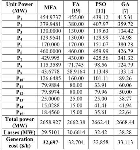
Table 3 Comparison table for IEEE 15- unit test system (Pd=2630 MW) with transmission loss.
Unit Power
(MW) MFA
FA [19]
PSO [11]
GA [7] P1 454.9737 455.00 439.12 415.31 P2 379.9481 380.00 407.97 359.72 P3 130.0000 130.00 119.63 104.42 P4 129.9541 130.00 129.99 74.98 P5 170.000 170.00 151.07 380.28 P6 460.0000 460.00 459.99 426.79 P7 429.995 430.00 425.56 341.32 P8 115.3589 71.745 98.56 124.79 P9 43.6778 58.9164 113.49 133.14 P10 126.6485 160.00 101.11 89.26 P11 79.9884 80.00 33.91 60.06 P12 79.8974 80.00 79.96 50.00 P13 25.0000 25.00 25.00 38.77 P14 15.0288 15.00 41.41 41.94 P15 18.4560 15.00 35.61 22.64 Total power
(MW) 2658.927 2662.38 2662.41 2668.44
Losses (MW) 29.5101 30.6614 32.42 38.28 Generation
cost ($/h) 32,697 32,704 32,858 33,113
References
[1] A. Badri, S. Jadid and M. Parsa-Moghaddam, “Impact of participants’ market power and transmission constraints on GenCos’ Nash equilibrium point”, Iranian Journal of Electrical and Electronic Engineering, Vol. 3, Nos. 1 & 2, pp.1-9, Jan. 2007.
[2] M. R. Aghamohammadi, “Static security constrained generation scheduling using sensitivity characteristics of neural network”, Iranian Journal of Electrical and ElectronicEngineering, Vol. 4, No. 3, pp. 104-114, Jul. 2008.
[3] L. Derong and C. Ying, “Taguchi Method for Solving the Economic Dispatch Problem With Non smooth Cost Functions”, IEEE transactions on power systems, Vol. 20, No. 4, pp. 2006-2014, Nov. 2005.
[4] S. Duman, U. Güvenç and N. Yörükeren, “Gravitational Search Algorithm for Economic Dispatch with Valve-Point Effects”, International Review of Electrical Engineering, Vol. 5, No. 6, pp. 2890-2895, Dec. 2010.
[5] D. C. Walters and G. B. Sheble, “Genetic Algorithm Solution of Economic Dispatch with Valve Point Loading”, IEEE Transactions on Power Systems,Vol. 8, No. 3, pp. 1325-1332, Aug. 1993.
[6] A. Bakirtzis, V. Petridis and S. Kazarlis, “Genetic Algorithm Solution to the Economic Dispatch Problem”, Proceedings. Inst. Elect. Eng. – Generation, Transmission Distribution, Vol. 141, No. 4, pp. 377-382, July 1994.
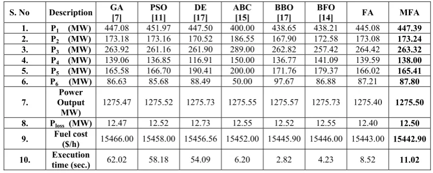
Table 4 Comparison table Showing Simulation Result of 6-generator unit (Pd=1263 MW) with various optimization methods.
[7] G. B. Sheble and K. Brittig, “Refined genetic algorithm- economic dispatch example”, IEEE Trans. on Power Systems, Vol. 10, pp. 117-124, Feb. 1995.
[8] N. Sinha, R. Chakrabarti and P. K. Chattopadhyay, “Evolutionary programming techniques for economic load dispatch”, IEEE Transactions on Evolutionary Computation, Vol. 7, No. 1, pp. 83-94, Feb. 1996.
[9] C. T. Su and C. T. Lin, “New approach with a Hopfield modeling framework to economic dispatch”, IEEE Transactions on Power Systems, Vol. 15, No. 2, pp. 541-545, 2000.
[10] J. G. Vlachogiannis and K. Y. Lee, “Economic Load Dispatch - A Comparative Study on Heuristic Optimization Techniques with an Improved Coordinated Aggregation-Based PSO”, IEEE Transactions on Power Systems, Vol. 24, No. 2, pp. 991-1001, May 2009.
[11] J. B. Park, K. S. Lee, J. R. Shin and K. Y. Lee, “A Particle Swarm Optimization for Economic Dispatch with Nonsmooth Cost Functions”, IEEE Transactions on Power Systems, Vol. 20, No. 1, pp. 34-42, Feb. 2005.
[12] J. B. Park, Y. W. Jeong, J. R. Shin and K. Y. Lee, “An Improved Particle Swarm Optimization for Nonconvex Economic Dispatch Problems”, IEEE Transactions on Power Systems, Vol. 25, No. 1, pp. 156-166, Feb. 2010.
[13] I. A. Selvakumar and K. Thanushkodi, “A new particle swarm optimization solution to non convex economic load dispatch problems”, IEEE Transactions on Power Systems, Vol. 22, No. 1, pp. 42-51, Feb. 2007.
[14] B. K. Panigrahi and V. R. Pandi, “Bacterial foraging optimization: Nelder-Mead hybrid algorithm for economic load dispatch.” IET Gener. Transm, Distrib. Vol. 2, No. 4. pp. 556-565, 2008.
[15] D. Karaboga and B. Basturk, “Artificial Bee Colony (ABC) Optimization Algorithm for Solving Constrained Optimization Problems”, Springer-Verlag, IFSA, LNAI, Vol. 4529, pp. 789–798, 2007.
[16] R. Storn and K. Price, Differential Evolution-A Simple and Efficient Adaptive Scheme for Global Optimization Over Continuous Spaces, International Computer Science Institute,, Berkeley, CA, 1995, Tech. Rep. TR-95-012. [17] A. Bhattacharya and P. K. Chattopadhyay,
“Biogeography-Based Optimization for Different Economic Load Dispatch Problems”, IEEE Transactions on Power Systems, Vol. 25, No. 2, pp. 1064-1077, May 2010.
[18] X. S. Yang, Firefly algorithm, Levy flights and global optimization, Research and Development in Intelligent Systems XXVI, Springer, London UK, pp. 209-218, 2010.
[19] X.-S. Yang, S. S. Sadat Hosseini, and A. H. Gandomi, “Firefly Algorithm for solving non-convex economic dispatch problems with valve loading effect”, Applied Soft Computing, Vol. 12, No. 3, pp. 1180-1186, 2012.
[20] X. S. Yang, “Firefly algorithms for multimodal optimization”, Proceedings of the Stochastic Algorithms: Foundations and Applications (SAGA ’09), Vol. 5792 of Lecture Notes in Computing Sciences, pp. 178-178, Springer, Sapporo, Japan, Oct. 2009.
R. Subramanian received the B.E. degree in Electrical and Electronics Engineering from Coimbatore Institute of Technology in the year 2005 and M.E degree in Power Systems Engineering from Government College of Technology, Coimbatore in the year 2007. He is currently doing PhD in the area of Power system control and S. No Description GA [7] PSO [11] [17] DE ABC [15] BBO [17] BFO [14] FA MFA
1. P1 (MW) 447.08 451.97 447.50 400.00 438.65 438.21 445.08 447.39
2. P2 (MW) 173.18 173.16 170.52 186.55 167.90 172.58 173.08 173.24
3. P3 (MW) 263.92 261.16 261.90 289.00 262.82 257.42 264.42 263.32
4. P4 (MW) 139.06 136.85 116.91 150.00 136.77 141.09 139.59 138.00
5. P5 (MW) 165.58 166.70 190.41 200.00 171.76 179.37 166.02 165.41
6. P6 (MW) 86.63 85.68 88.49 50.00 97.67 86.88 87.21 87.80
7.
Power Output MW)
1275.47 1275.52 1275.73 1275.55 1275.57 1275.73 1275.40 1275.50
8. Ploss (MW) 12.47 12.52 12.73 12.55 12.52 12.55 12.40 12.50 9. Fuel cost ($/h) 15466.00 15458.00 15456.56 15452.00 15445.90 15446.00 15443.00 15442.90
10. time (sec.) Execution 62.02 58.18 54.09 6.20 2.82 4.23 8.52 11.02
operation under Anna University. Presently he is working as an Associate professor in the Department of Electrical and Electronics Engineering at Akshaya College of Engineering and Technology, Coimbatore. His research interests are power system analysis, power system control and operation, mathematical computations, optimization and Soft Computing Techniques.
K. Thanushkodi received his B.E. degree in Electrical and Electronics Engineering from College of Engineering, Guindy in the year1972. He has received M.Sc. (Engg.) degree from PSG College of Technology, Coimbatore in the year1974. He has received PhD degree in Power Electronics from Bharathiyar University in the year 1991. Presently he is the Director of Akshaya College of Engineering and Technology, Coimbatore and he is a former Syndicate Member, Anna University of Technology, Coimbatore. His research interests are Power Electronics Drives, Electrical Machines, Power Systems, and Soft Computing techniques, Computer Networks, Image Processing and Virtual Instrumentation.
A. Prakash received the B.E degree in Electrical and Electronics Engineering from Sri Nandhanam College of Engineering and Technology in the year 2005 and M.Tech degree in Power Electronics and Drives from PRIST University, Tanjore in the year 2011. He is currently working as an Assistant Professor in the Department of Electrical and Electronics Engineering at Akshaya College of Engineering and Technology, Coimbatore. His research interests are Power System Modelling and Analysis and Power Electronic applications to Power Systems.