SPICE COMPATIBLE MODEL FOR MULTIPLE
COUPLED NONUNIFORM TRANSMISSION LINES:
APPLICATION IN TRANSIENT ANALYSIS OF
VLSI CIRCUITS
Ahmad Cheldavi and Davood Ansari
Department of Electrical Engineering, Iran University of Science and Technology Narmak, 16844, Tehran, Iran, [email protected]
(Received: April 9, 2002 – Accepted in Revised Form: November 5, 2003)
Abstract An SPICE compatible model for multiple coupled nonuniform lossless transmission
lines (TL's) is presented. The method of the modeling is based on the steplines approximation of the nonuniform TLs and quasi-TEM assumptions. Using steplines approximation the system of coupled nonuniform TLs is subdivided into arbitrary large number of coupled uniform lines (steplines) with different characteristics. Then using modal decomposition method the system of coupled partial differential equations for each step is decomposed to a number of uncoupled ordinary wave equations describing uncoupled uniform TLs in each step. To satisfy the boundary conditions at the discontinuities a new model is developed. Therefore each step of the system can be modeled in SPICE using a set of ideal delay lines representing uncoupled TLs and some linear-dependent voltage and current sources. Finally some examples are given to show the validity and usefulness of the model.
Key Words VLSI Circuits, Interconnect, Transient Analysis, SPICE Model
ƵŶǀƨģ ƵŶǀƨģ ƵŶǀƨģ ƵŶǀƨģ
źǀƛƩŚƤŤƳřƍƺƐųŚŝŹŚĭŻŚſƩŶƯƦƿƶƫŚƤƯƲƿřŹŵ ƵŶƃƶŗřŹřƞƬţƱƹŶŝƵŶƃŪƿƹżţƾƿŚţŶƴģƲĮưƷ
Ţſř
. ƶŞƃ ŹŚƄŤƳřƉźƟƶƿŚě źŝƩŶƯ Ʋƿř
TEM
źǀƛƍƺƐųƽřźŝƽř ƶƬěŜƿźƤţƁƹŹ ƹ
ƵŶƃƵŵŚƸƳ Śƴŝ ƲĮưƷ
Ţſř
.
ŶƃŪƿƹżţƲĮưƷźǀƛƩŚƤŤƳřƍƺƐųƮŤƀǀſƽřƶƬěŜƿźƤţŻřƵŵŚƠŤſřŚŝ
ƩŚƤŤƳřƍƺƐųƾƷřƺŴƫŵŵřŶƘţƶŝƵ
ƾƯƮǀƀƤţŶƴŤƀƷƾţƹŚƠŤƯšŚƈŴƄƯƽřŹřŵƶƧƵŶƃŪƿƹżţƲĮưƷ ŵƺƃ
.
ƩřŵƺƯƦǀƨƠţƁƹŹŻřƵŵŚƠŤſřŚŝžĜſ
ƎųƵŶƴƴƧƞǀƇƺţũƺƯƶƫŵŚƘƯƽŵřŶƘţšŹƺƇƶŝƽřƶƬěźƷƶŝƍƺŝźƯƾŗżūšŚƈŴƄƯŚŝƪǀƀƳřźƠƿŵšLJŵŚƘƯ
ŶƿōƾƯŹŵƵŶƃƦǀƨƠţƩŚƤŤƳř
.
Śƴƛřƽřźŝ
ƾĮŤƀƀĭŹŵŵƺūƺƯƽŻźƯƎƿřźƃƽ
ŵŚŬƿřƽŶƿŶūƁƹŹŵƺūƺƯƽŚƷ
Ţſř ƵŶƃ
.
ƾƯƪǀƫŵƲǀưƷƶŝ
ŹřżƟřƭźƳŹŵřŹƮŤƀǀſƶƬěźƷ Ʊřƺţ
SPICE ƞǀƇƺţƶƧƾƫř ƵŶƿřźǀųŚţƍƺƐųŚŝ
ƾƯŦŰŝŵŹƺƯƵŶƃƦǀƨƠţƩŚƤŤƳřƍƺƐųƵŶƴƴƧ
ƞǀƇƺţƶŤƀŝřƹƱŚƿźūƹĥŚŤƫƹƖŝŚƴƯ ƽŵřŶƘţƲǀƴĤưƷƹŶƴƃŚŝ
ŵźƧ
.
ƳŹŵ ŢſřƵŶƃƶŗřŹřŶƴŤƀƷƁƹŹƱŵƺŝŶǀƠƯƹŢŰƇźŝƽŶƷŚƃƶƧƩŚŨƯƽŵřŶƘţŢƿŚƸ
.
1. INTRODUCTION
The analysis and modeling of multiple coupled micro strip and other TLs and interconnects has been a topic of considerable interest in VLSI design and microwave integrated circuit technologies. As clock rates increase and inter-line spacing decrease, an accurate analysis of pulse propagation in multiconductor, coupled TL's becomes more important. A considerable amount of work has been done on the applications, analysis, and simulation of multiple coupled TLs [1-36]. For example authors of [3] used iteration-perturbation approach in spatial domain. Also the
time. Also several SPICE compatible [11-19], and other circuit simulation-models [20-36] has been presented by several authors. For example for the case of lossless uniform lines with frequency-independent line constants, a SPICE model based on modal decomposition method was proposed in [11]. This model leads to a circuit model consisting of linear-dependent sources and ideal delay elements representing uncoupled TLs. Almost the same principle has been used by several authors to obtain a SPICE model for different applications [12-16]. The principles of configuration-oriented SPICE model for homogeneous and inhomogeneous medium were presented in [16, 17]. Authors of [18] present a new SPICE compatible model for almost all types of TLs But the authors do not give computed example for the case of nonuniform TLs. This makes it difficult to decide whether the presented method in [18] is computationally efficient for multiple coupled nonuniform TLs.
In this paper a simple SPICE compatible model for multiple coupled nonuniform loss less TL's is presented. The geometry under considerations includes M (arbitrary number) of coupled nonuniform planar TLs each with different tapering in width and spacing. The method is based on the quasi-TEM assumptions for the coupled TLs and step lines approximation. Using step lines approximation, the system of coupled nonuniform TLs is decomposed into (N) arbitrary large number of coupled uniform step lines with different characteristics. Then using modal decomposition method the system of coupled partial differential equations for each step are decomposed to M uncoupled ordinary wave equations which are then modeled using ideal delay lines in SPICE and linear-dependent voltage and current sources. To satisfy the boundary conditions at the discontinuities, the continuity condition for the voltages and currents are imposed using a proposed linear model, which can be simulated using some linear-dependent voltage and current sources. The step line approximation is the only source of error in this paper. The method proposed here has been verified by comparing its results, with those obtained by other methods. It is a fast and convenient method for investigating time-domain near- and far-end cross talks and other related quantities that are of utmost
importance in interconnect performance analysis.
2. REVIEW OF MODAL DECOMPOSITION METHOD
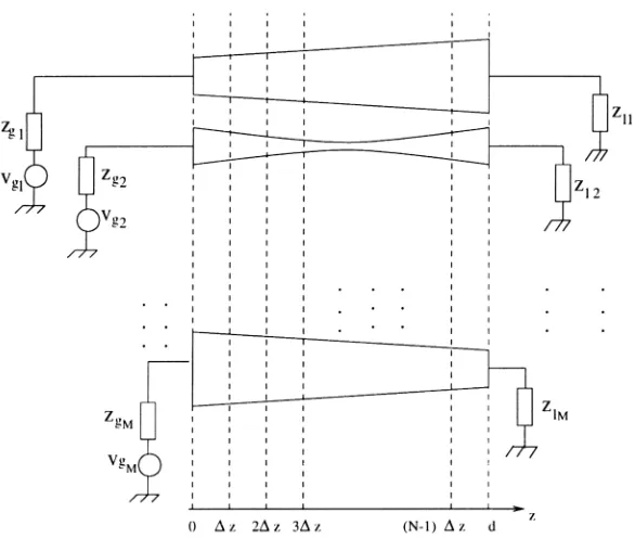
Consider a system of M-coupled nonuniform transmission lines with equal lengths, terminated by arbitrary complex loads as shown in Figure 1. This can be considered as a circuit model for typical high speed digital interconnects. To find the model of this configuration, the total length of the coupled lines d is subdivided to N equal (without loss of generality) intervals∆z. The inductance, capacitance, resistance, and conductance matrices of the coupled TLs over each subinterval are taken to be independent of z. The partial differential equations, which describe the system in the n-th step, are given by
0 )] , ( [ ] [ )] , ( [ = ∂ ∂ + ∂ ∂ z t z i L z t z
v k n
n n k (1) 0 )] , ( [ ] [ )] , ( [ = ∂ ∂ + ∂ ∂ z t z v C z t z
i k n
n n
k (2)
Where [vk(t,z)]n, [ik(t,z)]n, [C]nand [L]nare 1
×
M voltage and current vectors, and M×M
capacitance and inductance matrices of the coupled TLs at the n-th step respectively. Note that the matrices [L]n and [C]n are symmetric as a consequence of the reciprocity properties for the electromagnetic fields. Furthermore, they are assumed to be strictly positive definite.
Using the "modal decomposition" method [1], one may decouple [1,2] by simultaneously diagonal zing [L]n and [C]n matrices. The modal variables are defined by
n k n v n m
k z t T v z t
v ( , )] [ ] [ ( , )]
[ = (3)
n k n i n m
k z t T i z t
i ( , )] [ ] [ ( , )]
[ = (4)
n m k t z
v ( , )]
[ and [ikm(t,z)]n represent voltage and current modal vectors. A simple method to obtain
n v
T ]
[ and [Ti]n is given in several references [1, 2]. Substituting 3 and 4 in 1 and 2 leads to the uncoupled set of partial differential equations as
0 )] , ( [ ] [ )] , ( [ = ∂ ∂ + ∂ ∂ z t z i L z t z
v km n
n m n m k (5) 0 )] , ( [ ] [ )] , ( [ = ∂ ∂ + ∂ ∂ z t z v C z t z
i km n
n m n
m
k (6)
In which [Lm]nand [Cm]narc diagonal matrices defined for the n-th step as:
1 ] [ ] [ ] [ ]
[Lm n = Tv n Lm n Ti −n (7)
1 ] [ ] [ ] [ ]
[Cm n = Ti n Lm n Tv −n (8)
Therefore by using proper transfer matrices
n v
T ]
[ and [Ti]n for the n-th step, the coupled equations [1,2] arc now decoupled to M uncoupled
wave equation in terms of modal variables.
3. EQUIVALENT SPICE MODELS FOR UNIFORM COUPLED TL's STEP
Consider n-th uniform coupled transmission lines step with length∆z. Note that the distance for the n-th step is measured fromz=(n−1)∆z. From [3,4] one can relate the voltages and currents of the modal and main lines as (for0≤z≤∆z)
) , ( 1s v z t
v M rn
r n r k m n
k = ∑= (9)
) , ( 1 t z v p
v M rmn
r n
r k n
k = ∑= (10)
) , ( 1t i z t
i M rn
r n r k m n
k = ∑= (11)
) , ( 1q i z t
v M rmn
r n
r k n
k = ∑= (12)
In which sknr, pknr, tknrand, qknr are elements of the k-th row and r-th column of [Tv]n, [Tv]−n1,
n i
T]
[ and [ ]−1
n i
T respectively, and m n k
v , vkn, m n k
i
and ikn represent the modal and main voltages and currents of the k-th line and n-th step. According to
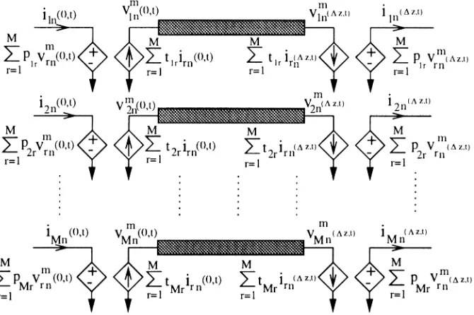
these equations and based on modal decomposition method discussed briefly in previous section several equivalent models for uniform coupled lines can be derived. Two equivalent SPICE models for the uniform coupled TL's structure are shown in Figures 2 and 3. It is simple to show that these two models are equivalent.
Figure 2. SPICE Model of the n-th Uniform Coupled TLs Step.
4. SPICE MODEL FOR NONUNIFORM COUPLED TRANSMISSION LINES
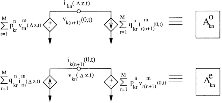
To find a suitable SPICE model first we have to impose the boundary conditions at the discontinuities of the adjacent steps. Boundary conditions at the discontinuity of the n-th and (n+l)-th steps are given by:
1 )] , 0 ( [ )] , (
[vk ∆z t n = vk t n+ (13)
1 )] , 0 ( [ )] , (
[ik ∆z t n = ik t n+ (14)
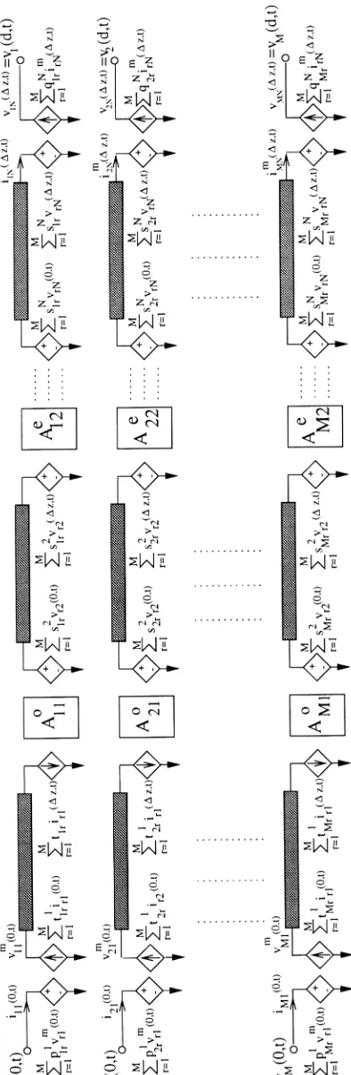
To impose these boundary conditions for the k-th line of k-the n-k-th step we use k-the following SPICE models (see Figure 4). Note that in this paper the model shown in Figure 2 is used for the first step, and Akon and vken are used when n is an odd or even number, respectively. Finally the SPICE compatible model for nonuniform coupled TLs structure is obtained as shown in Figure5.
5. EXAMPLES AND RESULTES
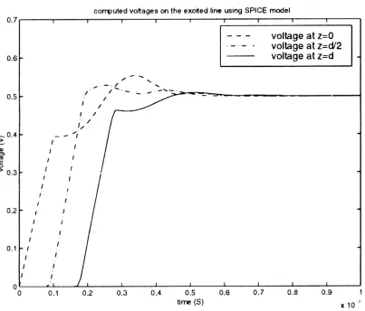
In the first example consider two conductor nonuniform TLs as shown in Figure 6. This
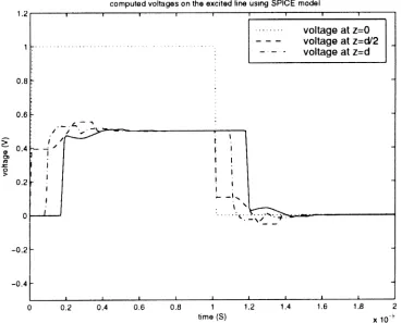
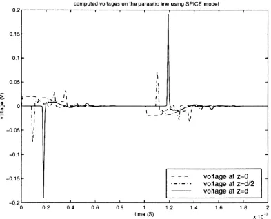
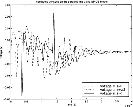
transmission system is considered in [4]. Terminations are considered to be 50Q pure resistive. The total length of the nonuniform section of the lines is subdivided to 6 steps. Parameters of the lines for each step are given in [4]. The voltage waveforms at some points of the excited (active) and parasitic (passive) lines using SPICE model of this system are shown in Figures 7 and 8.
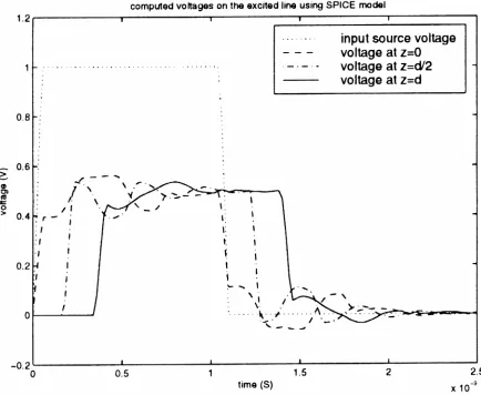
As the second example consider the same structure as shown in Figure 6. Now we want to investigate the effect of the rise and fall times of the input signal on the signal propagation and crosstalk. Figures [9-10] show the voltage at various points of the lines for a signal with 0.01 Ps rise and fall times. As it is clear the magnitude of the crosstalk signal is magnified for this case. In the third example we put two coupled systems as shown in Figure 6 in cascade to form the structure shown in Figure 11. This structure is now modeled using the proposed SPICE compatible model. The voltage waveforms at some points of the excited (active) and parasitic (passive) lines are shown in Figures 12 and 13.
6. CONCLUSIONS
coupled TLs for evaluating the transient response was presented. It can he used for VLSI nonuniform interconnect analysis and design. The accuracy of the present model has been verified by comparing
its results with those obtained using other methods. The most advantage of such modeling scheme is that each physical point of the system can be easily accessed. So the voltage and current at arbitrary Figure 6. The transmission system in Example 1.
Figure 8. Voltages for the various points of the parasitic line (Compare the voltage at z =0 and z = d with Figure 9).
points of the lines can be monitored, and the effect of external electromagnetic fields on the system can be considered by adding proper additional input sources at suitable points of the model.
7. REFERENCES
1. Lei, G. T., Pan, G. W. and Gilbert, B. K., “Examination, Clarification and Simplification of Modal Decoupling Method for Multiconductor Transmission Lines”, IEEE Figure 10. Voltages for the various points of the parasitic line.
Trans. Microwave Theory Tech, Vol. 43, No. 9, (Sep. 1995), 2090-2099.
2. Marx, K. D., "Propagation Modes, Equivalent Circuits and Characteristic Terminations for Multiconductor TLs with Inhomogeneous Dielectrics”, IEEE Trans.
Microwave Theory Tech., Vol. 21, (July 1995), 450-457.
3. Mehalic, M. A. and Mittra, R., "Investigation of Tapered Multiple Microstrip Lines for VLSI Circuits", IEEE
Trans. Microwave Theory Tech., Vol. 38, No. L, (Nov.
1990), 1559-1566.
4. Palusinski, 0. A. and Lee, A., "Analysis of Transients in Nonuniform and Uniform Multi Conductor TLs", IEEE
Trans. Microwave Theory Tech., Vol. 37, No. 1, (Jan.
1989), 127-138.
5. Pan, G. W., Wunsch, G. J. and Gilbert, B. K., "Frequency-Domain Analysis of Coupled Nonuniform TLs Using Chebyshev Pseudo-Spatial Techniques”,
IEEE Trans. Microwave Theory Tech., Vol. 40, No. 2,
(Nov. 1992), 2025-2033,
6. Yang, Y., Kong, J. and Gu, Q., "Time-Domain Perturbational Analysis of Nonuniform Coupled TLs,"
IEEE Trans. Microwave Theory Tech., Vol. 33, (Nov.
1985), 1120-1130.
7. Mao, J. F. and Li, Z. F., "Analysis of Time Response of Nonuniform Multiconductor TL with Frequency Dependent Losses by the Method of Convolution Characteristics”, IEEE Trans. Microwave Theory Tech., Vol. 40, No. 4, (April 1992), 637-644.
8. Mao, J. F. and Li, Z. F., "Analysis of Time Response of Nonuniform Multiconductor TL with a Method of Equivalent Cascaded Network Chain”, IEEE Trans.
Microwave Theory Tech., Vol. 40, No. 5, (May 1992),
948-954.
9. Djordjevic, A. R., Sarkar, T. K. and Harrington, R. F., "Analysis of Lossy TLs with Arbitrary Nonlinear Terminal Networks", IEEE Trans. Microwave Theory Figure 12. Input voltage waveform and voltages at sonic points of the excited line for input
Tech., Vol. 34, No. 6, (June 1986), 660-666.
10. Djordjevic, A. R. and Sarkar, T. K., "Analysis of Time Response of Lossy Multiconductor TL Networks", IEEE
Trans. Microwave Theory Tech., Vol. 35, No. 10, (Oct.
1987), 898-908.
11. Tripathi, V. K. and Rettig, J. B., "A SPICE Model for Multiple Coupled Microstrip and other TLs", IEEE
Trans. Microwave Theory Tech., Vol. 33, No. 12, (Dec.
1985), 1513-1518,
12. Paul, C. R., "A SPICE Model for Multiconductor TLs Excited by an Incident Electromagnetic Field", IEEE
Trans. Electromagnetic Compatibility, Vol. 36, No.4,
(Nov. 1994), 342-352.
13. Romeo, F. and Santomaru, M., " Time-Domain Simulation of n Coupled TLs", IEEE Trans. Microwave
Theory Tech, Vol. 35, No. 2, (Feb. 1987), 131-136.
14. Maio, I., Canavero, F. G. and Dilecce, B., "Analysis of Crosstalk and Field Coupling to Lossy MTLs in a
SPICE Environment", IEEE Trans. Electromagnetic
Compatibility, Vol. 38, No. 3, (Aug. 1996), 221-229.
15. Broyde, F., Clavelier, E., Vaillant, F. and Bigot, S., "Crosstalk and Field to Wire Coupling Problems: The SPICE Simulator Approach", in Proc. 9th Int. Zurich
Symposium of Electromagnetic. Compatibility, (Mar.
12-14, 1991), 23-28.
16. Broyde, F., Clavelier, B. and Hymovitz, C., "Simulating Crosstalk and Field-to-Wire Coupling with a SPICE Simulator", IEEE Circuits Devices, Vol. 8, No. 5, (Sep. 1992), 8-16.
17. Tripathi, A. and Tripathi, V. K., "A Configuration-Oriented SPICE Model for Multiconductor TLs in an Inhomogeneous Medium", IEEE Trans. Microwave
Theory Tech., Vol. 46, No. 12, (Dec.1998), 1997-2005.
Theory Tech., Vol. 38, (Aug. 1990), 1133-1129. 19. Celik, M., Cangellaris, A. C. and Yaghmour, A., "An
All-Purpose Transmission-Line Model for Interconnect Simulation in SPICE", IEEE Trans. Microwave Theory
Tech., Vol. 45, No. 10, (Oct. 1997), 1857-1867.
20. Mittra, R., Becker W. D. and Harms, P. H., "A General Purpose Maxwell Solver for the Extraction of Equivalent Circuits of Electronic Package Components for Circuit Simulation", IEEE Trans. Circuits Systems - I:
Fundamental Theory and Applications, Vol. 39, No. II,
(Nov. 1992), 964-973.
21. Roychowdhury, J. S., Newton, A. R. and Pederson, D. C., "Algorithms for Transient Simulation of Lossy Interconnect", IEEE Trans. Computer-Aided Design, Vol. 13, No. 1, (Jan. 1994), 96-103.
22. Lee, D. and. Palusinski, 0. A., “Modification of "SPICE" for Simulation of Coupled Packaging Interconnections", IEEE Trans. Corn., Hybrids Manufacturing.
Technology, Vol. 15, No. 4, (Aug. 1992), 491-496.
23. Griffith, R., Chiprout, E., Zhang, Q. J. and Nakhla, M., "A CAD Framework for Simulation and Optimization of High-Speed VLSI Interconnections", IEEE Trans. Circuits Systems – I. Fundamental Theory and
Applications, Vol. 39, No. 2, (Nov. 1992), 893-905.
24. Romeo, F. and Santomauro, M., "Time-Domain Simulation of n Coupled TLs”, IEEE Trans. Microwave
Theory Technology, Vol. 36, (Feb. 1987), 131-136.
25. Dhaene, T., Martens, L. and Zutter, D. D., "Transient Simulation of Arbitrary Nonuniform Interconnection Structures Characterized by Scattering Parameters", IEEE Trans. Circuits Systems - I: Fundamental Theory
and Applications, Vol. 39, No. 2, (Nov. 1992), 928-937.
26. Alonso, J. I., Borja, J. and Perez, F., "A Universal Model for Lossy and Dispersive TLs for Time Domain CAD of Circuits", IEEE Trans. Microwave Theory Tech, Vol. 40, No. 5, (May 1992), 938-946.
27. Bracken, J. E. Raghavan, V. and Rohrer, R. A. "Interconnect simulation with asymptotic waveform evaluation (AWE))" IEEE Trans. Circuits Systems - I:
Fundamental Theory and Applications, Vol. 39, No.
(II), (Nov.l992) pp. 869-877.
28. Pan, G. W., Prentice, J. A., Zahn, S. K., Staniszewski, A. J. and ..., "The Simulation of High-Speed, High-Density Digital Interconnects in Single Chip Packages and
Multichip Modules", IEEE Trans. Corn., Hybrids,
Manufacturing Technology, Vol. 15, No. 4, (Aug. 1992),
465-477.
29. Lin, S. and Kuh, E. S., "Transient Simulation of Lossy Interconnects Based on the Recursive Convolution Formulation", IEEE Trans. Circuits Systems - I:
Fundamental Theory and Applications, Vol. 39, No.
2, (Nov. 1992), 879-891.
30. Mao, J. F. and Kuh, E. S., "Fast Simulation and Sensitivity Analysis of Lossy TLs by the Method of Characteristics", IEEE Trans. Circuits Systems - I:
Fundamental Theory and Applications, Vol. 44, No.
5, (May 1997), 391-401.
31. Chang, F. Y., "Relaxation Simulation of Transverse Electromagnetic Wave Propagation in Coupled TL",
IEEE Trans. Circuits Systems, Vol. 38, No. 8, (Aug.
1991), 916-936.
32. Beyene, W. T. and Schutt-Aine, J. E., "Accurate Frequency-Domain Modeling and Efficient Circuit Simulation of High-Speed Packaging Interconnects",
IEEE Trans. Microwave Theory Tech, Vol. 45, No. 10,
(Oct. 1997), 1941-1947.
33. Braunish, H. and Grabinski, H., "Time-Domain Simulation of Large Lossy Interconnect-Systems on Conducting Substrate", IEEE Trans. Circuits Systems
- I: Fundamental Theory and Applications, Vol. 45, No.
9, (Sep. 1998), 909-918.
34. Celik, M. and Pileggi, L. T., "Simulation of Lossy Multiconductor TLs Using Backward Euler Integration", IEEE Trans. Circuits Systems - I: Fundamental Theory
and Applications, Vol. 45, No. 3, (March 1998), 238-243.
35. Palusinski, O. A. Liao, J. C. Prince, J. L. and Cangellaris, A. C., "Simulation of Transients in VLSI Packaging Interconnections", IEEE Trans. Corn., Hybrids,
Manufacturing Technology, Vol. 13, (1990), 160-166.
36. Chang, E. C. and Kang, S, M. "Transients Simulation of Lossy Coupled TLs Using Iterative Linear Least Square Fitting and Piecewise Recursive Convolution", IEEE
Trans. Circuits Systems, Vol. 43, No. 2, (Nov. 1996),
923-932.