i tif c n
e C
i o
c n
S f
l e
a r
n e
o n
i c
t e
a 2
nr 0
et 1
1
n I
ISC 2011
Proceeding of the International Conference on Advanced Science,
Engineering and Information Technology 2011
Hotel Equatorial Bangi-Putrajaya, Malaysia, 14 - 15 January 2011
ISBN 978-983-42366-4-9
ISC 2011
International Conference on Advanced Science, Engineering and Information Technology
ICASEIT 2011
Cutting Edge Sciences for Future Sustainability
Hotel Equatorial Bangi-Putrajaya, Malaysia, 14 - 15 January 2011
SR
IE
AUNVIIT
NI
ES E
D K
O B
IN N
R AG
JA A
L S
A A
E N
P M
N A
A L
U A
T Y
A S
S A I
R
EPNOI TAI COSSA STNEDUTS NA ISENN IOD Organized by Indonesian Students Association Universiti Kebangsaan Malaysia Proceeding of the
Robust Optimal Controller Design for Induction
Generator Driven by Variable-Speed Wind Turbine
with STATCOM Using Immune Algorithm
Majid Naserian#, Abolfazl Karimi#, Seyed Esmaeil Mirabdolahi#
# Department of Electrical Engineering, Islamic Azad University, Mehriz Branch
mehriz, 8981883114, Iran
Tel.:+983525229100, E-mail: [email protected]
Abstract
—
this paper presents the modelling, controller design and a steady-state analysis algorithm for a wind-driven induction generator system. An output feedback linear quadratic controller is designed for the static synchronous compensator (STATCOM) and the variable blade pitch in a wind energy conversion system (WECS) in order to reach the voltage and mechanical power control under both grid-connection and islanding conditions. A two-reference-frame model is proposed to decouple the STATCOM real and reactive power control loops for the output feedback controller. To ensure zero steady-state voltage errors for the output feedback controller, the integrals of load bus voltage deviation and dc-capacitor voltage deviation are employed as the additional state variables. Pole-placement technique is used to determine a proper weighting matrix for the linear quadratic controller such that satisfactory damping characteristics can be achieved for the closed-loop system. Effects of various system disturbances on the dynamic performance have been simulated, and the results reveal that the proposed controller is effective in regulating the load voltage and stabilizing the generator rotating speed for the WECS either connected with or disconnected from the power grid. In addition, proper steady-state operating points for an isolated induction generator can be determined by the proposed steady-state analysis algorithm. Constant output frequency control using the derived steady-state characteristics of the isolated induction generator is then demonstrated in this paper.Keywords— Induction generator (IG), static synchronous compensator (STATCOM), voltage regulation, wind energy conversion system (WECS), wind turbine
I. INTRODUCTION
Induction generators are being increasingly utilized in a wind energy conversion system (WECS) since they are relatively inexpensive, rigid, and require low maintenance. However, the impact of everchanging wind speed on power quality, coupled with the need of excitation current for induction generator (IG), make the mechanical power control and voltage regulation indispensable to the wind-driven induction generator system. By far, the most effective way of controlling the mechanical power captured by the wind turbine is to adjust the rotor blade pitch angle. Blade pitch is analogous to the throttle valve in conventional steam turbines, except that the speed of control is much faster than the governor control in a steam turbine [1], [2]. It can be employed to regulate mechanical power input and real power output of the WECS. However, the reactive power required by the IGcan be provided by a shunt
capacitor bank, but it may cause excessive overvoltage during disconnection. Moreover, the amount of capacitance required for excitation varies with the generator speed [3]. Thus, if a fixed shunt capacitor is connected across the terminals of the IG, the terminal voltage will vary with generator speed. To achieve continuous voltage
Regulation under varying system conditions, static
synchronous compensators (STATCOMs), have been
employed in the literatures. The basic principle of a STATCOM installed in a power system is to generate a controllable ac voltage behind a coupling transformer and a filter by a voltage-sourced inverter (VSI) connected to a dc capacitor. The output voltage of the VSI can be controlled to be greater than the line voltage in order to provide reactive power to the wind-driven IG.
generator around a specific operating point was given in. Nevertheless, for the WECS, it is impractical and uneconomical to fix the generator output power (or rotor speed) at a specific operating point sincethe wind speed changes all the time. Besides, the controller design based on the constant output power (or rotor speed) considerations under grid-connection condition would fail in islanding operation.
In this paper, an output feedback controller is designed to regulate system voltage and mechanical power under both grid-connection and islanding conditions. The major features of the proposed output feedback controller are summarized as follows.
1) A systematic approach based on pole placement
technique has been applied to determine proper
weighting matrix for the linear quadratic controller such that the eigenvalues for the closed-loop system can be shifted to desirable locations. As a result, satisfactory transient excursion suppression in system voltages and generatorspeed can be reached by the controller when the WECS is subjected to major disturbances.
2) The integrals of load bus voltage deviation and dc-capacitor voltage deviation are employed as additional state variables to eliminate the steady-state voltage errors for the output feedback controller.
3) A control scheme with two reference frames is proposed to reach the decoupled control for the STATCOM real and reactive power control loops in case of voltage uc-tuations, no matter what kind of disturbances may take place.
4) A simple algorithm is developed to determine proper steady-state operating points for an isolated IG. Using the relationship between the generator speed and the output power at various frequencies, a proportional-integral controller is proposed to achieve constant frequency control for an isolated IG with sufficient mechanical power.
II. SYSTEMMODELS
Fig. 1 depicts the one-line diagram of an induction generator driven by a variable-speed wind turbine and connected to a grid through a transmission line. An output feedback controller is utilized to control the wind turbine mechanical power and the system reactive power through the variable blade pitch and the STATCOM, respectively. The reactive power required by the IG
In steady-state operating condition is supplied by a fixed shunt capacitor bank, as shown in Fig. 1. To maintain constant load bus voltage (VL) under disturbance conditions, a STATCOM which is capable of adjusting its output voltage and reactive power output based on system requirements, is employed. The STATCOM is connected to the load bus through a coupling transformer and a filter. Note that a constant
impedance load isassumed in Fig. 1.
Fig. 1. System configuration
A. Induction Generator Model
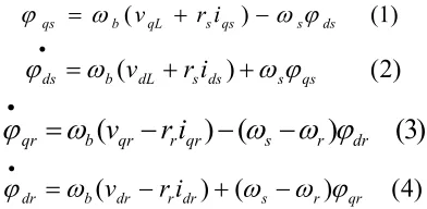
The per unit ux-linkages for the stator and rotor circuits of the induction generator described in d- and q-axes are as follows [3]:
(1) )
( qL s qs s ds
b
qs
ω
v r iω
ϕ
ϕ
• = + −)
2
(
)
(
dL s ds s qsb
ds
ω
v
r
i
ω
ϕ
ϕ
•=
+
+
)
3
(
)
(
)
(
qr r qr s r drb
qr
ω
v
r
i
ω
ω
ϕ
ϕ
•=
−
−
−
)
4
(
)
(
)
(
dr r dr s r qrb
dr
ω
v
r
i
ω
ω
ϕ
ϕ
•=
−
+
−
Where a synchronous reference frame rotating at the electrical angular speed corresponding to the fundamental frequency of the grid voltage, herein denoted as s, is adopted. The electromechanical torque in per unit can be written in terms of stator ux linkages and currents as
)
5
(
ds qs qs ds
e
i
i
T
=
φ
−
φ
The per unit rotor acceleration is given by
)
6
(
)
(
2
1
ur T e m T u
r
T
T
D
H
ω
ω
•=
−
−
Where Tm is the per unit mechanical torque of the wind turbine, and HT and DT are the equivalent inertia constant and the equivalent damping constant of the wind
turbine-inductiongenerator system, respectively.
B. Wind Turbine Model
The mechanical power output of a wind turbine can be
writtenas [1]
3
2
1
w p
m
AC
V
P
=
ρ
(7)
Where is the air mass density, Vw is the wind speed, A is the rotor swept area, and Cp is a power coefficient representing the fraction of power extracted from the aerodynamic power in the wind by a practical wind turbine.
following closed-form approximate relationship for Cp is used: γ
β
γ
R pe
R
C
17 . 02
5
.
6
)
022
.
0
(
2
1
−
−
−=
(8) The tip speed ratio is defined as
w T
V
R
ω
γ
=
(9) ٌhere ωT is the rotating speed of the wind turbine.
mechanical torque are the Wind turbines can obtain the following equation
(10)
γ
ρπ
2 pw 3 m
C
V
R
2
1
T
=
It is observed from (9)–(10) that the mechanical power output of a wind turbine is related to the turbine speed
T
ω , wind speed Vw , and the pitch angleβ . An
increase in the pitch angle, which results in a decrease in the power coefficient Cp , is efficient to control the mechanical power of the wind turbine.
C. STATCOM Model
For a balanced three-phase system, the STATCOM model can be described in per unit using the variables in d- and q-axes synchronous reference frame as [3]
)
e
V
(
X
i
i
X
r
i
dL df b qe s de f f b
de
=
+
+
−
⋅
ω
ω
ω
(11)
)
(
qL qf b de s qe f f b
qe
V
e
X
i
i
X
r
i
⋅=
ω
−
ω
+
ω
−
(12)
Where
i
de,i
qe,e
d,e
q,are current and voltage axis dand q STATCOM.and
V
dlوV
ql are bus voltages at theaxes d and q .
In Fig. 1, the instantaneous powers at the ac and dc sides of the voltage-sourced inverter are equal, giving the following power balance equation:
qe q de d dc
dc
i
e
i
e
i
V
=
+
(13) The per unit dc-side circuit equation is
)
r
V
i
(
C
1
V
dc dc dc dc .dc
=
−
(14)
Where rd c is used to represent the inverter switching loss.
D. Transmission line model
The per unit ux-linkages for the Transmission line described in d- and q-axes are as follows[4]
)
V
V
(
X
w
i
w
i
X
r
w
i
dL dTL b qTL s dTL TL TL b dTL ∞ ⋅
−
+
+
−
=
(15) ) ( ∞ ⋅ − + − −= qL q
TL b dTL s qTL TL TL b
qTL V V
X w i w i X r w i (16).
Where
V
q∞,
V
d∞ are per unit voltage at the axes q andd
E. Fixed a shunt capacitor model
The per unit ux-linkages for the Fixed a shunt capacitor described in d- and q-axes are as follows [4]
dfc c b ql s
dl
w
V
w
X
i
V
.=
+
(17) qfc c b dl s
ql
w
V
w
X
i
V
.=
−
+
(18)
F. Load model
. The per unit ux-linkages for the load described in d- and q-axes are as follows[4]
dL L b qL s dL L L b dL V X w i w i X r w
i⋅ =− + +
(19) qL L b dL s qL L L b qL V X w i w i X r w
i⋅ =− − +
(20)
III.LINEARIZATION EQUATIONS THE POWER SYSTEM UNDER STUDY
To determine the appropriate control signal for STATCOM, Dynamic equations of system under study can be Linearization as follows.
x
C
y
u
B
x
A
x
∆
∆
∆
∆
∆
=
+
=
⋅ (21) T qe de qTL dTL qs ds dr qr dc u r ql dl ql dli
i
i
i
v
w
i
i
v
v
x
]
,
,
,
,
,
,
,
,
,
,
,
,
,
[
∆
∆
∆
∆
∆
∆
∆
∆
∆
∆
∆
∆
∆
∆
=
∆
ϕ
ϕ
ϕ
ϕ
(22)Where
∆
x
,∆
u
,∆
y
are state vectors respectively,input and output system.
Mode input vector equations expressed in (23) T
q
d
,
e
,
]
e
[
u
∆
∆
∆
β
∆
=
(23) and output as vector is defined as (24)
x
C
]
i
,
i
,
w
,
v
,
v
[
y
T qe de u r dcL
∆
∆
∆
∆
∆
∆
∆
=
=
(24) Where output matrix c,is as as follow
T T 5 T 4 T 3 T 2 T
1
,
C
,
C
,
C
,
C
]
C
[
C
=
(25)The
C
1,C
2,C
3,C
4,andC
5 are sub matrix as follow
∆
v
dc=
C
2.
∆
x
،∆
v
L=
C
1.
∆
x
x
C
i
de=
∆
∆
4.
w
C
x
u
r
=
∆
∆
3.
x
C
i
qe=
∆
∆
5.
IV.IMMUNE EVOLUTIONARY ALGORITHM
Having computers that automatically solve problems without being explicitly programmed to be the main goal of Artificial Intelligence [5].
such as computer security, information analysis, classification, template matching and parametric optimization is used [6 , 7].
Clooney selection and placement antibodies with low degree of similarity is as follows.
1. Initialize: the initial set (population), called AB, the n number of antibody (Ab), i = 1, .., n is created.
2. Assessment: an antigen, Ag for the issue to be considered with all antibodies to be compared, as well as their degree of similarity fi which the antigens are determined.
3. Placement: The probability of a certain pr new antibody is produced and placed a new set, so that parameter pr is the probability of placement.
Similarity degree is proportional to the antigen. In short, each antibody with probability pc, and clones are placed in a new set of parameter pc is likely to be cloned.
4. Clone: when a new antibody in the previous step does not produce an antibody (Ab) from the current set is selected. Likely to choose a direct antibody
5. super shoot: If the antibody with a high degree of similarity of selected clones in the previous step is not part super shoot is sent, super shoot antibodies selected for each element of its corresponding string with mutation probability pm mutations occurred. The probability of similarity degree images antibody with antigen is.
6. Repeat - Category: Repeat steps 3 to 5 until a new set of size n AB be created.
7. Repeat algorithm: The new collection is produced and stage 2 (assessment) is sent, the process repeats until a stop condition continues.
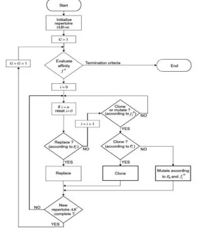
Flowchart continued safety, given the algorithm, details of which form (2) is given.
Fig2: flowchart Immune Algorithm
V. LQG CONTROLLER DESIGN
Now LQG controller design for the system being studied are paid. LQG controller block diagram form the figure (3) is:
Fig 3 LQG controller block diagram
In this figure target is set output (y) of the zero point.
State equation as relations (26) and (27) are:
Gw
Bu
Ax
x
&
=
+
+
(26)v
Hw
Du
Cx
y
=
+
+
+
(27)Where w and v are white noise model. LQG controller includes an optimal state feedback using a Kalman state estimate is nasty.
That the two sections independently, as explained below are designed.
A. Using State Feedback
In control, measurement by displaying second form of relation (28) is calculated.
{
x
Qx
x
Nx
u
u
R
u
}
dt
u
J
=
T+
T+
T∫
∞0
2
)
(
(28) Weight matrices Q and N and R by the efficiency and precision control are defined and determined.
The first step is to design a feedback
u
=
−
Kx
thatthe minimum cost function
J
(u
)
, the search will be.Coefficient matrix using the k to the minimum, using algebraic equations is obtained Rykaty. The coefficient of interest, using optimal LQ call.
If A, B, C and D matrix system under study and Q, R and N weight matrices are obtained, then use the coefficient K,gain of the LQ, relationship (29) is obtained.
)
.
,
,
,
(
A
B
Q
R
N
lqr
K
=
(29)B. Estimator State Kalman
State feedback LQ in relation
U
=
−
Kx
,on the polesplacement is not applicable unless all conditions measured are considered. This applies if the estimate of a state, as derived variables are therefore related (30) we have:
x
K
U
=
−
ˆ
(30)In orther to solve the Output feedback problem, or the remaining optimal state estimation by Kalman filter, which created the relation (31) is calculated.
)
ˆ
(
ˆ
ˆ
A
x
Bu
L
y
C
x
Du
x
dt
d
−
−
+
+
=
&
(31) With input u (controller) and the (measured) can be expressed.
Noise covariance information as relations (32) to (34) has been considered.
n
T
R
vv
n T
Q
ww
E
(
)
=
(33)n
T
N
wv
E
(
)
=
(34)By using Rykaty algebraic equations is determined a kalman gain
G. LQG optimal controller design by Immune Algorithm
Now LQG controller design using immune algorithm are paid. Design factor controller LQG, Immune algorithm with weight matrices R and Q is calculated. That, considering the importance and limit Drayhjhay two matrices, they were mentioned in the algorithm is given and the values obtained matrix. To optimize the control of optimal ITAE index is used as the relation (35) can be expressed.
dt
t
e
t
k
J
Ts
∫
×
=
0
)
(
(35) The index now studying for the system output
L
V
,V
dc,ω
randi
e is considered, that a relationship (36)is expressed.
dt
dc
V
Vdc
t
K
dt
l
V
Vl
t
K
J
=
1
∫
×
(
−
ˆ
)
+
2
∫
×
(
−
ˆ
)
dt
e
i
ie
t
K
dt
r
W
Wr
t
K
∫
×
−
+
∫
×
−
+
3
(
ˆ
)
4
(
ˆ
)
(36) The selection algorithm with different values
ultimately equal probability of insertion 0.4(
Pr
=
.
4
) hasbeen considered. Operation and also the possibility to
clone 0.7 (
Pc
=
.
7
) Is done. To achieve a morefavorable response with super shoot probability cloud
0.4(
Pm
=
.
4
) Algorithm is considered. And finally,considering the number of repeat times 400, Q and R weight matrices using the algorithm to come to the relationship (37) are:
)
3
(
*
6
.
0
eye
R
=
,0,0,0,0
0,0,1023,0
diag([0,0,
Q
=
(37))
11,511]
023,2047,5
,0,0,0,0,1
However the values obtained by optimal LQG control algorithm are designed to safety.
VI.THE SIMULATION RESULTS WITH THE LQG CONTROLLER
This section of LQG control poster designed in the previous section with the output feedback control be provided [8].
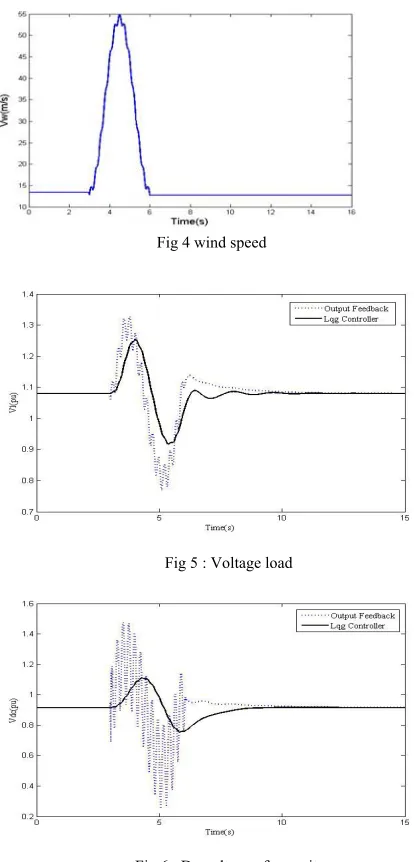
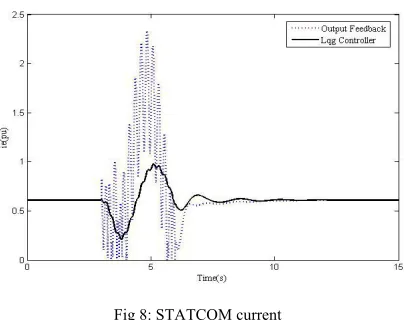
The comparison of system performance against the changing wind speed is examined. Changes in wind speed curve is shown in Figure (4). Voltage load curve
changes
(
V
L)
, capacitor voltage DC(
V
dc)
,rotorspeed
(
ω
r)
and current of STATCOM(
i
e)
, is shown infigure (5) to (8) respectively.
Fig 4 wind speed
Fig 5 : Voltage load
Fig 6 : Dc voltage of capacitor
Fig 8: STATCOM current
Same as that of the Find (5) to (8) is visible, provided LQG control design, the voltage regulation and load fluctuations also improved the damping system was very effective and provided feedback to the control output results with appropriate can be.
VII. SUMMARY
In this article, provided optimal control based method lqg, for the system under study was designed, the effects of changes in wind speed on the dynamic performance of building systems like and the results indicate that the control visitors' comment on the case terminal voltage
regulation and improved damping system oscillations has been very effective.
References
[1] W. El-Khattam, M. M. A. Salama, " Distributed generation technologies , definitions and benefits ", Electric Power Syst. Res., pp. 119-128, 2004.
[2] G. Pepermans, J. Driesen, D. Haeseldonckx, R. Belmans,W. D'haeseleer, "Distributed generation : definitions,benefits and issues ", Energy Policy, pp. 1-12 , 2003.
[3] Z. Saad, et al., “Application of STATCOMs to Wind Farms”, IEE-Gen. Trans. Dis., vol. 145, no 5, pp. 511-516, Sep. 1998.
[4] L. L. Freris, “Wind Energy Conversion Systems”, Englewood Cliffs, NJ: Prentice-Hall, 1990.
[5] G.F. Luger, Artificial Intelligence: Structures and Strategies for Complex Problem Solving,fourth ed., Addison–Wesley, 2002.
[6] A.E. Eiben, J.E. Smith, Introduction to Evolutionary Computing, Springer, 2003.
[7] D.B. Fogel, Evolutionary Computation: Toward a New Philosophy of Machine Intelligence,second ed., IEEE Press, Piscataway, NJ, 1999.