Please cite this article as: M. Zolfaghari, S. A. Taher,Fuzzy Approximation Model-based Robust Controller Design for Speed Control of BLDC Motor, International Journal of Engineering (IJE), TRANSACTIONS B: Aspects Vol. 28, No. 3, (March 2015) 426-432
International Journal of Engineering
J o u r n a l H o m e p a g e : w w w . i j e . i rFuzzy Approximation Model-based Robust Controller Design for Speed Control of
BLDC Motor
M. Zolfaghari*a, S. A. Taherb
aDepartment of Electrical Engineering, Feiz Institute of Higher Education, Kashan, Iran bDepartment of Electrical Engineering, University of Kashan, Kashan, Iran
P A P E R I N F O
Paper history: Received 09January 2014
Received in revised form 13November2014 Accepted 17January2015
Keywords:
BLDC Motor Fuzzy Approximation Robust Controller
A B S T R A C T
This paper presents a new controller for speed control problem of the BLDC motors. The nonlinear model of the motor is approximated by implementation of fuzzy rules. The uncertainties are considered in the fuzzy system. Using this model and linear matrix inequality (LMI) optimization, a robust controller for purpose of speed control of the motor has been designed and applied to it. The effectiveness of the designed controls demonstrated through simulation results.
doi: 10.5829/idosi.ije.2015.28.03c.12
NOMENCLATURE
Rotor position, rad )
(t
r
q
Stator winding currents, A )
( ), ( ),
(t I t I t
Ia b c
qd axis inductances, H d
q L
L ,
qd axis currents, A )
( ),
(t I t
Iq d
Mutual air gap flux linkages, V-s m
y
Stator back-emf, V )
( ), ( ),
(t e t e t
ea b c
Electromagnetic torque, N.m
T
Stator voltages, V )
( ), ( ),
(t V t V t
Va b c
Number of poles
P
qd axis voltages, V )
( ),
(t v t
vq d
Load torque, N.m L
T
Stator resistance/phase, Ω
R
Load inertia, kg-m2 J
Stator inductance, H
L
Viscous friction, N.m/(rad/s)
B
Rotor speed, rad/s )
(t
r
w
1. INTRODUCTION1
With rapid developments in power electronics, power semiconductor technologies, modern control theory for motors and manufacturing technology for high performance magnetic materials, the brushless DC (BLDC) motors have been widely used in many fields [1], including industrial automation, automotive,
1*Corresponding Author’s Email: [email protected] (M.
Zolfaghari)
aerospace, instrumentation and appliances since 1970’s [2]. The BLDC motor is a novel type of DC motor in which commutation is done electronically instead of using brushes. Therefore, it needs less maintenance, and due to the advancement of small size, good performance, simple structure, high reliability and large output torque have attracted increasing attention [1, 3]. There are two types of BLDC with respect to back-emf signal of motor; sinusoidal and trapezoidal. There are also two types of BLDC according to havingor not havingsensors for detecting rotor position [3]. Normally,
Hall Effect sensors were used for low cost, low resolution requirements and optical encoder for high resolution requirements [4]. Sensor signals are used to adjust PWM sequence of 3-phase bridge inverter . In sensor-less control back-emf sensing, back-emf integration, flux linkage- based, freewheeling diode conduction and speed independent position function technique are used for electronic commutation [5]. Due to electronical commutation, BLDC has more complex control algorithm compared to other motor types [3, 5]. In practice, the design of the BLDCM drive involves a complex process such as modeling, control scheme selection, simulation and parameters tuning etc. Recently, various modern control solutions are proposed for the speed control design of BLDC motor [1-3]. However, Conventional PID controller algorithm is simple, stable, easy adjustment and high reliability. Conventional speed control system used in conventional PID controller. But, in fact, most industrial processes have been with different degrees of nonlinear, parameter variability and uncertainty of mathematical model of the system. Tuning PID control parameters is very difficult due to its poor robustness; therefore, it is difficult to achieve the optimal state under field conditions in the actual production [6]. So far, there have been many different design methods and control schemes to overcome the uncertain nonlinear control problems such that neural network control system has a strong ability to solve the structure uncertainty but it requires more computing capacity and data storage space. For genetic algorithms, ant-colony algorithms, techniques can help improving performance but they also need longer computation time and larger storage capacity [7-11].
To design the BLDC motor drive system, it is necessary to have motor model give precise value of torque which is related to current and back-EMF [12]. Different models have been presented to analyze performance of BLDC motor [1-5], [11, 12]. However, the model of the motor is highly nonlinear. In this paper, the nonlinear model of the motor has been approximated by using Takagi-Sugeno (TS) fuzzy approximation model. Recently, the design of fuzzy H∞for a class of nonlinear systems which can be represented by a Takagi-Sugeno (TS) fuzzy model has been considered by many researchers[13-17]. In this TS Fuzzy model, local dynamics in different state space regions are represented by local linear systems. The overall model of the system is obtained by ‘blending’ these linear models through nonlinear membership functions. Hence, the aim of this paper is to design a robust H∞
based on linear matrix inequality (LMI) approach for speed control problem of the BLDC motors. This controller is designed such that the £2 gain of the mapping from the exogenous input noise to the regulated output is less than a prescribed value.
Figure 1. Overall diagram of BLDC motor with proposed controller
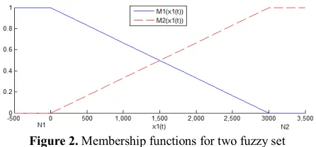
Figure 2. Membership functions for two fuzzy set
2. MATHEMATICAL MODEL
The overall system model is shown in Figure 1. As shown, it contains a 3-phase full bridge voltage source inverter supplying the BLDC motor. The inverter, in turn, is controlled through the signals of the robust controller.This controller generates the control signals using multiple feedback loops of currents and rotor position and has been designed in comingsections.
3. DYNAMIC MODEL OF BLDC MOTOR
The coupled circuit equations of the 3-phase BLDC motor are [18]:
ú ú ú
û ù
ê ê ê
ë é + ú ú ú
û ù
ê ê ê
ë é
ú ú ú
û ù
ê ê ê
ë é + ú ú ú
û ù
ê ê ê
ë é
ú ú ú
û ù
ê ê ê
ë é = ú ú ú
û ù
ê ê ê
ë é
) (
) (
) (
) (
) (
) (
0 0
0 0
0 0
) (
) (
) (
0 0
0 0
0 0
) (
) (
) (
t e
t e
t e
t i
t i
t i
dt d
L L L
t i
t i
t i
R R R
t v
t v
t v
c b a
c b a
c b a
c b a
(1)
Also, back-emf is depend to position of rotor because the permanent magnet is rotating with speed of rotor. So, the relationship between back-emfs and the function of rotor speed can be written as follows [19]:
ú ú ú ú ú ú
û ù
ê ê ê ê ê ê
ë é
+ -=
ú ú ú
û ù
ê ê ê
ë é
) 3 2 sin(
) 3 2 sin(
) sin( )
( ) (
) (
) (
p q
p q
q y
w
r r
r
m r c
b a
t t
e t e
t e
(2)
The abcvariable via the Park’s transform are applied such that the rotor frame qdvariable is obtained. A set of voltage is obtained as [20]:
) ( ) ( ) ( )
( )
( t t t
dt d t Ri t
) ( ) ( ) ( ) ( )
( t t t
dt d t Ri t
vd = d + yd -wr yq (4)
) ( ) ( )
(t L q t iq t
q =
y (5)
m d
d
d t L t i t y
y ( )= ( ) ( )+ (6)
And the electromagnetic torque of the motor is [20]:
(
)
(
( ) ( ) ( ) ( ))
2 3 ) ( )( t P i t L L i t i t
Tiqid = y m q + q - d q d (7)
Combining with equation of motion, the system equations in terms of the
qd
variables can be written as follows: ï ï ï ï ï ï î ïï ï ï ï ï í ì · · -+ -= + -= + -= · · · ) ( 1 ) ( ) ( ) ( ) ( ) ( 1 ) ( ) ( ) ( ) ( ) ( ) ( () () 2 3 ) ( t v L t i L R L L t i t t i t v L L L t i t t i L R t L t i t d d d d d q q r d q q q d d r q q r q m q t T J P t i J P t J Br r mq L
w
w w
y
w w y
(8)
Choosing the state variables as;
) ( ) ( ), ( ) ( ), ( )
( 2 3
1 t t x t i t x t i t
x =wr = q = d , the system from (8)
can be described by the following state equations:
ï ï ï ï ï ï ï î ï ï ï ï ï ï ï í ì · · -+ -= = + -= + -= · ) ( ) ( ) ( 1 . 0 ) ( ) ( ) ( ) ( ) ( 1 . 0 ) ( ) ( ) ( ) ( ) ( 1 1 3 2 1 3 2 3 1 2 1 2 ) ( ) ( 2 3 ) ( )
( 1 2 3
1 t x t z t w t x L R L L t x t x t x t w L L t x t x t x L R t x L t x x d d q q d q q m t w J P t x J P t x J B t m y y (9)
where w1(t)and w2(t)are the process noise, w3(t) the disturbance factor from torque load and z(t) the controlled output.
4. FUZZY APPROXIMATION AND NONLINEAR FUZZY MODE
Here, attention is particularly given to generalize the TS fuzzy system to represent a TS fuzzy system with parametric uncertainties. The TS fuzzy system with parametric uncertainties considered is as follows:
( )[ ] ( )[ ] ( )[ ]
å
å
å
= = = · D + + D + = D + + D + = D + + D + + D + = ri i i i i i
r
i i i i i i
r
i i i i i i i i
t w D D t x C C t v t y t u D D t x C C t v t z t u B B t w B B t x A A t v
t
x
1 2 2 21 21
1 1 1 12 21
1 1 1 2 2
) ( ] [ ) ( ] [ ) ( ) ( ) ( ] [ ) ( ] [ ) ( ) ( ) ( ] [ ) ( ] [ ) ( ] [ ) (
)
(
m m m (10)wherev(t)=[vi(t)...vJ(t)] is the premise variable vector that may depend on states in many cases, mi( )v(t) denotes the normalized time-varying fuzzy weighting functions
for each rule (i.e., mi( )v(t) ³0and å ( )
= =
r
i1miv(t) 1),J the number of fuzzy sets, x(t)ÎÂn the state vector,
m
t
u()ÎÂ the input, w(t)ÎÂp
the disturbance which belongs toL2 [0,∞], y(t)ÎÂl the measurement, and
s
t
z()ÎÂ the controlled output.The matrices
i i i i
i B C C D
A, 1, 1, 2, 12and D21iare of appropriate dimension, and r is the number of IF-THEN rules. The matrices; DAi,DB1i,DC1i,DC2i,DD12i and DD21i represent the
uncertainties in the system and satisfy the following assumptions:
( )
( ) ( )
( ) ( )
( ) i i ( ) i
i i i i i i i i i i i H t t x F D H t t x F D H t t x F C H t t x F C H t t x F B H t t x F B H t t x F A 7 21 6 12 5 2 4 1 3 21 2 1 1 ), ( , ), ( ), ( , ), ( ), ( , ), ( ), ( = D = D = D = D = D = D = D (11)
whereHij= 1, 2… 7 are known matrix functions which characterize the structure of the uncertainties. Furthermore, the following inequality holds:
(xt t)£r
F ( ), (12)
for any known positive constant ρ. If
g
is a given positive number, then system is said to have L2-gainless than or equal to
g
if :0 ) 0 ( , ] ) ( ) ( [ ) ( ) ( 0 0 2 = £
ò
z t z t dtò
w t w t dt xf f
T T
T
T g (13)
for all Tf³0andw(t)ÎL2[0,Tf]. Note that for the
symmetric block matrices, we use (#) as an ellipsis for terms that are induced by symmetry.It is found that currents and the speed in dynamic model of BLDC motor from (9) are highly nonlinear. Thus, the nonlinearity and various uncertainties including external disturbances have to be taken into account. The nonlinear system plant can be approximated by TS fuzzy sets as Figure 2, the membership function can be written as:
(
)
1 2(
)
1 21 1 2 1
2 1 2 1
( ) ( )
( ) x t N ; ( ) x t N
M x t M x t
N N N N
- + +
= =
- - (14)
Using this membership functions, we can approximate the plant model as follows:Plant Rule I:
IF x1(t)Î
[
-N1 N1]
is M1(
x1(t))
THEN1 1 1 2 2 3 1 1 2 3 3 0 0 0
2 ( )
( ) 1
( ) ( ) 0
( ) ( )
1
0 0
0 0 ( )
0 0.1 0 ( ) ,
0.1 0 0 ( )
m
m
q q q
d d
B P
J J x t
u t R
t N x t
u t
L L L
x t R N L L P w t J w t w t x y y ·
é ù é ù
ê- ú ê ú
ê úé ù ê ú
ê úê ú ê ú é ù
= -ê - - úê ú+ê ú ê ú+
ê úê ú ê ú ë û
ë û
ê ú ê ú
ê - ú ê ú
ê ú ê ú
ë û ë û
é - ù
ê ú é ù
ê ú ê ú
ê ú ê ú
ê ú êë úû
ê ú
ë û
[ ] 12 3
( ) ( ) 1 0 0 ( ) ( )
x t z t x t x t
é ù
ê ú
= ê ú
ê ú
ë û
This can be written as: ) ( ) ( ) ( ) ( ) ( )
( 1 1
t Cx t z t w B t u B t x A t w x = + + = · (16)
Plant Rule II:
IF x1(t)Î[-N2 N2] is ( ()) 1 2 x t
M THEN
1 1 2 2 2 3 2 1 2 3 3 0 0 0
2 ( )
( ) 1
( ) ( ) 0
( ) ( )
1
0 0
0 0 ( )
0 0.1 0 ( ) ; (
0.1 0 0 ( )
m
m
q q q
d d
B P
J J x t
u t R
t N x t
u t
L L L
x t R N L L P w t J
w t z t w t
x
y y
·
é ù é ù
ê- ú ê ú
ê úé ù ê ú
ê úê ú ê ú é ù
= -êê - - úúê ú+êê ú ëú ê úû+
ê ú
ë û
ê ú ê ú
ê - ú ê ú
ê ú ê ú
ë û ë û
é - ù
ê ú é ù
ê ú ê ú
ê ú ê ú
ê ú êë úû
ê ú
ë û
[ ] 12
3
( ) ) 1 0 0 ( ) ( ) x t x t x t é ù ê ú
= ê ú
ê ú ë û
(17)
This can be written as:
) ( ) ( ) ( ) ( ) ( )
( 2 2
t Cx t z t w B t u B t x A t w
x
= + + = · (18)Using the values of parameters in Table 1 we have:
[1 0 0]
, 0 0 1 . 0 0 1 . 0 0 253 . 7042 0 0 , 393 . 47 0 0 393 . 47 0 0 175 . 33 0 175 . 33 976 . 4 0 154 . 1109 80 , 175 . 33 0 175 . 33 976 . 4 0 154 . 1109 80 2 2 2 1 1 1 = ú ú ú û ù ê ê ê ë é -= ú ú ú û ù ê ê ê ë é = ú ú ú û ù ê ê ê ë é -= ú ú ú û ù ê ê ê ë é -= C B B N N A N N A w i (19)
5. ROBUST CONTROLLER DESIGN
Here, we are going to find a robust H¥controller of the
form:
(
)
å
=
= r
j j j
t x K t v t u 1 ) ( ) ( )
( m (20)
2 2
1 1 1 1
[( ) ( )] ( )
( )
[ ] ( )
r r
i i j i i j
i j
i j i i
A B K A B K x t
t
B B w t
x
· m m= =
+ + D +
é ù
= ê ú
+ + D
ë û
åå
(21)where x(0)=0.
For the system (10), a given prescribed H¥
performance g >0 and positive constantd, if there is a matrix P=PT and matrices
r j
Yj, =1,2,..., , satisfying the
following linear matrix inequalities (LMI):
r j i r i P ji ij ij £ < < W + W = < W > 0 ,..., 2 , 1 0 0 (22) Where: ÷ ÷ ÷ ø ö ç ç ç è æ -+ -+ + + = W I Y D P C I B B Y Y B PA P A j i i T T i T T T i T j j i T i i ij g g 0 ) (# ) (# ) (# ( 12 1 1 2 2 (23) with [ ] 2 / 1 1 1 2 2 12 6 3 12 12 4 1 1 1 1 ] [ 1 2 2 0 2 2 0 ÷÷ ø ö çç è æ + = úû ù êë é = úû ù êë é = = å å = = r i r j T i T T i T i T i i T T i T i T i i i i H D H H D C H H C B I I I B r l lr lr d gr lr lr d gr d d (24)
Then, inequality (13) holds. Also, a suitable choice of the controller is:
( )
å
=
= r
j j j
t x K t v t u 1 ) ( ) ( )
( m (25)
where:
1
-= Y P
K j j (26)
Using the LMI optimization algorithm and following the Equation (13) with set asg=1, we obtain:
ú û ù ê ë é-= ú û ù ê ë é -= ú û ù ê ë é = ú û ù ê ë é -= ú ú ú û ù ê ê ê ë é = 989 . 0 0011 . 0 9577 . 0 0875 . 0 7548 . 15 0822 . 1 , 0098 . 0 4583 . 0 0024 . 0 86 . 1 0071 . 0 543 . 1 76318 . 0 0025 . 0 8795 . 0 0053 . 0 2413 . 12 016 . 0 , 0054 . 0 015 . 0 0 2347 . 0 045 . 0 541 . 0 6578 . 2 0 0 0 6578 . 2 0034 . 0 0 5671 . 0 247 . 1 2 1 2 1 K K Y Y P (27)
6. SIMULATION RESULTS
In this section, two case studies were considered to evaluate the performance of proposed robust controller. In the first case, an optimal PI controller was designed and applied to the BLDC motor. In the second case, the performance of the proposed robust controller was extensively compared to that of [6].
Case I. Proportional–integral (PI) type controllers are commonly used in industrial applications. Thus, it is worth comparing the performance of these controllers as opposed to common robust controller mentioned here. In this study, for the purpose of comparison, a PI controller is considered for speed control of BLC motor and its parameters have been optimized by using genetic algorithm (GA) [21]. In the GA optimization, the optimization objective function is considered as the integral time absolute error (ITAE) .This well-known index could be used for optimization and controller tuning and is defined as:
ò
D = t dt t ITAE 0 w (28)is minimized using GA. In order to acquire better performance, population size, number of chromosomes, mutation rate and mutating rate are chosen as 80, 4, 10% and 50%, respectively. The obtained parameters of the optimal PI are KP =0.8 andKI =0.02.
The specification of the examined BLDC motor considered in the simulation is given in Table 1 . All simulations have been evaluated extensively using commercially available software package, MATLAB12. Each simulation result presented in this section consists of two different plots (PI controller and Robust controller). The results of the time-domain simulations are shown in Figure 3. These figures show simulation results for speed reference input of 1800 rpm with a step change in load torque. The disturbance input signals
) (
1t
w ,w2(t) and w3(t) which were used during the
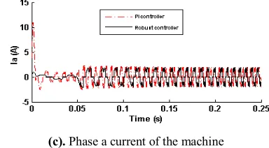
simulation are given in Figure 4. Figure 3 (a) shows overshoot in speed is zero for the case of using the robust controller and settling time is about 0.04 sec. whereas these values for the PI controller are about 33% and 0.28 sec. respectively. Figure 3 (b) shows the electromagnetic torque of the motor dramatically has fewer ripples by implementing of the robust controller than the PI controller. The current of phase “a” of the machine also is shown in Figure 3 (c). This figure shows that the current waveform is smoother by use of the robust controller compared to the case of PI controller.
Case II. Here, the performance of the proposed robust controller was compared to the adaptive fuzzy proportional-integral- derivative (PID) controller suggested by [6]. The simulation results are shown in Figure 5. As shown in Figure 5 (a), the settling time has been reduced by using the proposed robust controller. Figures 5 (b), (c) show that the ripple in the electromagnetic torque and in the phase current, with the proposed robust controller, is much lower than those with the fuzzy PID controller introduced in [6].
(a). Rotor speed
(b). Electromagnetic torque
21The MATHWORKS, “MATLAB Software”, , Version 7.14, Inc., 2012
(c). Phase a current of the machine
Figure 3. Simulation results, Case I: response of BLDC motor with the designed robust and PI controllers for a step change in load torque.
Figure 4. Disturbance inputsw1(t),w2(t) and w3(t) used in simulation.
TABLE 1.BLDC motor specification
Parameter Value
Rated power 2 hP
Number of poles 4 Number of phases 3
Connection Star
13658 2.4544
160 V 0.7 Ω 0.105 Wb Self-inductance 2.72 mH Mutual inductance 1.5 mH Motor inertia (J) 0.000284 kg.m2
Damping constant (B) 0.02 N.m/rad/sec
(a). Rotor speed dc
V
S R
(b). Electromagnetic torque
(c). Phase a current of the machine
Figure 5. Simulation results, Case II: Response of BLDC motor with the designed robust and fuzzy controller of [6] for a change in load torque.
7. CONCLUDING REMARKS
Brushless DC (BLDC) motors are preferred as small horsepower control motors due to their high efficiency, silent operation, compact form, reliability, and low maintenance. However, the problems are encountered in these motor for variable speed operation over last decades continuing technology development in power semiconductors, microprocessors,adjustable speed drivers control schemes and permanent-magnet brushless electric motor production have been combined to enable reliable, cost-effective solution for a broad range of adjustable speed applications.
In this paper, the nonlinear model of brushless DC motor was approximated using implementation of fuzzy rules. Based on this model, linear matrix inequality algorithm, and H∞ theorem, a new robust controller was designed for speed control of BLDC motor. Simulation results demonstrated the effectiveness of the proposed controller in reducing the ripple in torque and zero overshoot in speed response of the motor.
8. REFERENCES
1. Savio, M. and Murugesan, S., "Space vector control scheme of three level zsi applied to wind energy systems", International Journal of Engineering-Transactions C: Aspects, Vol. 25, No. 4, (2012), 275-282.
2. Kebbati, Y., "Modular approach for an asic integration of electrical drive controls", International Journal of Engineering-Transactions B: Applications, Vol. 24, No. 2, (2011), 107-118.
3. Shaeiri, Z. and Ghaderi, R., "Modification of the fast global k-means using a fuzzy relation with application in microarray data analysis", International Journal of Engineering-Transactions C: Aspects, Vol. 25, No. 4, (2012), 283-292.
4. Ojaghi, M., Sabouri, M., Faiz, J. and Ghorbanian, V., "Exact modeling and simulation of saturated induction motors with broken rotor bars fault using winding function approach",
International Journal of Engineering-Transactions A: Basics, Vol. 27, No. 1, (2013), 69-78.
5. Afjei, E., Hashemipour, O., Saati, M. and Nezamabadi, M., "A new hybrid brushless dc motor/generator without permanent magnet", International Journal of Engineering Transactions B Applications, Vol. 20, No. 1, (2007), 77-86.
6. Kandiban, R. and Arulmozhiyal, R., "Design of adaptive fuzzy PID controller for speed control of bldc motor", International Journal of Soft Computing and Engineering, Vol. 2, No. 1, (2012), 386-391.
7. W. Assawinchaichote and N. Chayaopas, "Robust h∞ fuzzy speed control design for brushless dc motor", World Academy of Science, Engineering and Technology, (2013).
8. Chen, H., Huang, M., Liaw, C., Chang, Y., Yu, P. and Huang, J., "Robust current control for brushless DC motors", IEE Proceedings-Electric Power Applications, Vol. 147, No. 6, (2000), 503-512.
9. Gupta, R., Kumar, R. and Bansal, A.K., "Artificial intelligence applications in permanent magnet brushless DC motor drives",
Artificial Intelligence Review, Vol. 33, No. 3, (2010), 175-186. 10. P. Yedamale, "An885-brushless DC (BLDC) motor
fundamentals", Microchip Technology Inc, (2003).
11. Shanmugasundram, R., Zakariah, K.M. and Yadaiah, N., "Digital implementation of fuzzy logic controller for wide range speed control of brushless dc motor", in Vehicular Electronics and Safety (ICVES), 2009 IEEE International Conference on, IEEE, (2009), 119-124.
12. Jeon, Y., Mok, H., Choe, G., Kim, D. and Ryu, J., "A new simulation model of BLDC motor with real back emf waveform", in Computers in Power Electronics, 2000. COMPEL 2000. The 7th Workshop on, IEEE, (2000), 217-220.
13. Han, Z. and Feng, G., "State feedback H∞ controller design of fuzzy dynamic systems using lmi techniques", in Fuzzy Systems Proceedings, 1998. IEEE World Congress on Computational Intelligence., The 1998 IEEE International Conference on, IEEE, Vol. 1, (1998), 538-544.
14. Choi, J., Park, C.-W., Rhyu, S. and Sung, H., "Development and control of bldc motor using fuzzy models", in Robotics, Automation and Mechatronics, 2004 IEEE Conference on, IEEE. Vol. 2, No. Issue, (2004), 1180-1185.
15. Chen, B.-S., Tseng, C.-S. and Uang, H.-J., "Mixed h 2/H∞ fuzzy output feedback control design for nonlinear dynamic systems: An lmi approach", Fuzzy Systems, IEEE Transactions on, Vol. 8, No. 3, (2000), 249-265.
16. Assawinchaichote, W., Nguang, S.K., Shi, P. and Boukas, E.-K., "H∞ fuzzy state-feedback control design for nonlinear systems with-stability constraints: An lmi approach", Mathematics and Computers in Simulation, Vol. 78, No. 4, (2008), 514-531. 17. Gao, Q., Zeng, X.-J., Feng, G., Wang, Y. and Qiu, J., "T–
s-fuzzy-model-based approximation and controller design for general nonlinear systems", Systems, Man, and Cybernetics, Part B: Cybernetics, IEEE Transactions on, Vol. 42, No. 4, (2012), 1143-1154.
Intelligent Control and Automation, 2006. WCICA 2006. The Sixth World Congress on, IEEE. Vol. 2, (2006), 6498-6502. 19. Lee, C. and Kwok, N., "Reduced parameter variation sensitivity
with a variable structure controller in brushless DC motor velocity control systems", in Industry Applications Society Annual Meeting, 1993., Conference Record of the 1993 IEEE, IEEE, (1993), 746-753.
20. Pillay, P. and Krishnan, R., "Modeling of permanent magnet motor drives", in Robotics and IECON'87 Conferences, International Society for Optics and Photonics, (1987), 289-293. 21. Haupt, R.L. and Haupt, S.E., "Practical genetic algorithms, John
Wiley & Sons, (2004).
Fuzzy Approximation Model-based Robust Controller Design for Speed Control of
BLDC Motor
M. Zolfagharia, S. A. Taherb
aDepartment of Electrical Engineering, Feiz Institute of Higher Education, Kashan, Iran bDepartment of Electrical Engineering, University of Kashan, Kashan, Iran
P A P E R I N F O
Paper history: Received 09 January 2014
Received in revised form 13November 2014 Accepted 17 January 2015
Keywords:
BLDC Motor Fuzzy Approximation Robust Controller
هﺪﯿﮑﭼ
لﺮﺘﻨﮐﮏﯾﻪﻟﺎﻘﻣﻦﯾارد هﺪﻨﻨﮐ
ﻪﻟﺎﺴﻣياﺮﺑﺪﯾﺪﺟي ﺖﺳاهﺪﺷﻪﺋاراﮏﺑورﺎﺟنوﺪﺑﻢﯿﻘﺘﺴﻣنﺎﯾﺮﺟيﺎﻫرﻮﺗﻮﻣﺖﻋﺮﺳلﺮﺘﻨﮐي
.
مﺪﻋو هﺪﺷهدزﺐﯾﺮﻘﺗيزﺎﻓﻖﻄﻨﻣﻦﯿﻧاﻮﻗزاهدﺎﻔﺘﺳاﺎﺑرﻮﺗﻮﻣﯽﻄﺧﺮﯿﻏلﺪﻣ ﺖﯿﻌﻄﻗ
هﺪﺷظﺎﺤﻟيزﺎﻓﻢﺘﺴﯿﺳردﺎﻫ ﺪﻧا
.
ﺳاﺎﺑ هدﺎﻔﺘ
ﻪﻨﯿﻬﺑﻢﺘﯾرﻮﮕﻟازاهدﺎﻔﺘﺳاﺎﺑﺰﯿﻧولﺪﻣﻦﯾازا يزﺎﺳ
LMI
لﺮﺘﻨﮐﮏﯾ، هﺪﻨﻨﮐ ﻪﺑوهﺪﺷﯽﺣاﺮﻃرﻮﺗﻮﻣﺖﻋﺮﺳلﺮﺘﻨﮐياﺮﺑموﺎﻘﻣي
ﺖﺳاهﺪﺷلﺎﻤﻋانآ
.
ﻪﯾورﻦﯾاندﻮﺑﺮﺛﻮﻣ ﻪﯿﺒﺷزاهدﺎﻔﺘﺳاﺎﺑرﻮﺗﻮﻣﺖﻋﺮﺳﺐﺳﺎﻨﻣلﺮﺘﻨﮐردﯽﻟﺮﺘﻨﮐي
هﺪﺷهدادنﺎﺸﻧيزﺎﺳ
ﺖﺳا
.
![Figure 5. Simulation results, Case II: Response of BLDC motor with the designed robust and fuzzy controller of [6] for a change in load torque](https://thumb-us.123doks.com/thumbv2/123dok_us/228248.2017383/6.595.83.261.99.345/figure-simulation-results-response-designed-robust-controller-change.webp)