Please cite this article as: A. Toloei, M. Zarchi, B. Attaran, Numerical Survey of Vibrational Model for Third Aircraft based on HR Suspension System Actuator Using Two Bee Algorithm Objective Functions, International Journal of Engineering (IJE), TRANSACTIONS C: Aspects Vol. 30, No. 6, (June 2017) 887-894
International Journal of Engineering
J o u r n a l H o m e p a g e : w w w . i j e . i rNumerical Survey of Vibrational Model for Third Aircraft based on HR Suspension
System Actuator Using Two Bee Algorithm Objective Functions
A. Toloeia, M. Zarchi*a, B. Attaranb
a Department of Aerospace Engineering, Shahid Beheshti University, Tehran, Iran b Department of Mechanical Engineering, Shahid Chamran University, Ahwaz, Iran
P A P E R I N F O
Paper history: Received 25 October 2016
Received in revised form 28 March 2017 Accepted 21 April 2017
Keywords: Airplane Model PID Approach
Multiobjective Optimization Semi active Vibration Absorber Artificial Bee Colony
A B S T R A C T
This research explains airplane model with two vertical vibrations for airframe and landing gear system. The purpose of this work is to advance vibrational model for study of adjustable vibration absorber and to plan Proportional-Integration-Derivative approach for adapting semi active control force. The coefficients of this method are modified as stated by Bee multiobjective optimization using minimizing accelerations and impact forces as objective functions. The consequences implies that the semi active shock absorber system based on artificial Bee colony improves passengers and ride comfort and fatigue life of fuselage, shock strut and tyre by reducing movement of body, suspension system and impact load in an important way compared to passive performance during touchdown phase with various sink speeds and runway surfacesfor robustness and sensitivity investigation of optimization performance.
doi: 10.5829/ije.2017.30.06c.09
NOMENCLATURE
A Effective area kp Proportional coefficient
Ao Orifice area ki Integration coefficient
ys Suspension travel kd Derivative coefficient
P0 Initial pressure E(t) Error signal
C2 Tyre damping coefficient ITAE Integral of the time weighted absolute value of the error
K2 Tyre stiffness coefficient Yg Runway excitation
1. INTRODUCTION1
Shock absorber characteristics of passive landing gear system are steady in various situations while in semi active performance they are adjustable. The passive suspension system has stable damping whilst in semi active suspension system, the hydraulic fluid flow to the shock absorber is adopted depending on impact loads during touchdown, by that means modifying the hydraulic damping. So the focus on semi active system is essential to conquer the hardships in conventional system.
*Corresponding Author’s Email: [email protected] (M. Zarchi)
Fighter aircraft vibration absorber system has been inspected on the basis of analysis and test procedure [1-5]. The aircrafts employ landing gears with passive procedure that are planned by the directors [6, 7]. Some research studies [8-10] focused on shock absorbers with active control for a domain of airplane speeds and for different runway surfaces. The investigation done in references [11, 12] has been undertaken for proving advantages of semi active and active shock strut compared to passive system using Bees algorithm.
degrees of freedom using Bees single objective method has been justified in the literature [16, 17]. Fuzzy logic as a intelligent control technique is applied for improvement of semi active performance in landing gear system with input constraint of orifice area [18-20].
In the second step, the mechanical model of passive and semi active suspension system as well as vibrational equations are obtained. The semi active control force caused by suspension system and control law for improvement of system performance is defined. In the next step, method of Bees multi objective algorithm for tuning of PID controller is described. In fifth step, dynamic responses for two sink speeds for passive and semi active performances consisting of fuselage bounce, suspension travel and air spring force are represented. At the end, conclusion and future work is deduced.
2. MODEL OF PASSIVE AND SEMI ACTIVE LANDING GEAR SYSTEM
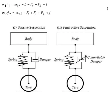
The semi active combination betters the performance of the suspension subsystem compared to passive approach by modifying quantity of oil flow [21-23]. The latter consists of a servo valve, an electronic controller and feedback transducers. When an aircraft lands, the shock absorber stroke is influenced by the aircraft’s payload and varies depending on runway excitation [14, 24, 25]. The stroke is measured by the transducers and their signals input into the electronic controller. Figure 1 is two degrees of freedom of aircraft model. They are the vertical displacement (bouncing) of sprung mass or body (y1) and vertical displacement of unsprung mass or tyre (y2) [26].
2. 1. Vibrational Equations of Semi Active Landing Gear System
1 1 1
2 2 2
m y m g L Fc Fk
m y m g Ft Fc Fk
f f
(1)
Figure 1. Mechanical model of passive and semi active suspension system for airplane
2. 2. Damping Force as Nonlinear Function
[ , , ( )] [A, A , ]
1 2
3
2
( ) sgn( )
1 2 1 2
2 2
2
Fc F A A y y F y
o o s
A
y y y y
Ao o
(2)
2. 3. Spring Force as Nonlinear Function
[p , (0 1 2)] [p ,0 ]
1 2
(1 )
0
0
Fk F y y F ys
y y p A y (3)
2. 4. Tyre Force
( ) ( )
2 2 2 2
Ft c y yg k y yg (4)
3. PID TECHNIQUE
The semi active control force caused by suspension system and control law for improvement of system performance is defined [27]. Error signal as controller input:
( ) ( ) (y1 y )( )2
e t r t t (5) The semi active control force for landing gear:
( )
( ) ( ) ( )
0
t de t Q t k e tp ki e t kd
dt
(6)
So,
( ) { ( ) (y1 y )( )}2
{ ( ) (y1 y )( )}2 { ( ) (y1 y )( )}2
Q t kp r t t ki r t t kd r t t
(7) where, ( ) ( )
Qsemiactive t F tc (8) So,
A ( ) { ( ) (y1 y )( )}2
{ ( ) (y1 y )( )}2 { ( ) (y1 y )( )}2
t kp r t t ki r t t kd r t t
o
(9)
4. BEE MULTIOBJECTIVE METHOD
N random numbers according to equation are choosed for each of the three PID gains.
These random numbers are introduced in
coefficients of PID controller.
Six degrees of freedom simulink model is run.
Objective function for accelerations and impact forces is calculated.
These N numbers are sorted in accordance with quantity of objective functions.
First M numbers are kept and rest of them is removed.
Nep random numbers for first E numbers in neighbourhood of Ngh are selected.
Nsp random numbers for first M-E numbers in neighbourhood of Ngh are selected.
Quantity of objective functions for Nep and Nsp is calculated.
The most minimum objective functions for every neighbourhood is selected and residue are omitted.
N-M random numbers for input margins of kp, ki and kd are choosed.
Refering to five step, this action is lasted until multiobjective function is minimized.
[ ]1 { ( ) . } { ( ) . }
1 2
0 0
ITA E t e t dt y t e t dt y
(10)
[ ]2 { ( ) . } { ( ) . }
0 0
ITA E t e t dt F t e t dt F
c k
(11)
[ITAE]T [ITAE]1[ITAE]2 (12)
5. NUMERICAL SIMULATION
The dynamic responses for A6 airplane model using
numerical simulation in MATLAB Simulink
environment (type: variable-step and solver: ode45) are acquired in touchdown phase with sink speed of 3 m/s and 5 m/s. Simulink model for semi active system is illustrated in Figure 2 [29].
5. 1. Dynamic Responses of the Aircraft for Two
Sink Speeds and Uniform Runway In this part,
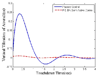
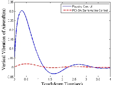
numerical simulation is obtained based on uniform runway. The aircraft is in touchdown phase. Three sink speeds are considered (3 m/s as light landing and 5 m/s as hard landing). Suspension travel is investigated as the most important parameter for evaluation of passive and semi active performances and comparison of them for passengers comfort and fatigue life of body and shock strut. This simulation is performed during 4 seconds as sample time.
Figures 3-8 show that the parameters of displacement consisting of body bounce and shock
absorber travel are increased with enhancement of sink speed. Table 1 is a comparison between dynamic responces for distinct velocities at touchdown moment. As the result of Table 1, the shock absorber displacements is bettered with increment of touchdown velocity about 85, 89 and 75%, respectively.
Figure 2. Simulink model for semi active control system
Figure 3. Time response of body bounce for sink speed=3 m/s
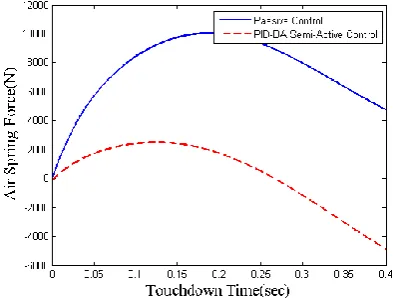
Figure 5. Time response of air spring force for sink speed=3 m/s
Figure 6. Time response of body bouncefor sink speed=5 m/s
Figure 7. Time response of shock strut travel for sink speed=5 m/s
5. 2. Dynamic Responses of the Aircraft for Two
Sink Speeds and Sine Wave Runway In this part,
numerical simulation is obtained based on sine wave runway according to Equation (13).
Figure 8. Time response of air spring force for sink speed=5 m/s
TABLE 1. Comparison of dynamic responses under uniform runway
Sink speed (m/s)
Suspension travel for passive system (m)
Suspension travel for semi active system (m)
3 0.24 0.01
5 0.29 0.03
The aircraft is in touchdown phase. Three sink speeds are considered (3 m/s as light landing and 5 m/s as hard landing). Body displacement, suspension travel and air spring force as impact force are investigated as important parameters for deliberation of passive and semi active performances and contrast of them for passengers comfort and fatigue life of body and shock absorber. This simulation is carried out during 4 seconds as simulation time.
where, the runway excitation:
0.1(1 cos 7.85 )
0 0.4
yg t
t
(13)
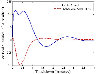
Figures 9-11 show that the parameters of displacement consist of fuselage and landing gear and impact force made up of air spring force decreases using semi active system significantly. Table 2 is a comparison between dynamic responces for velocity of 3 m/s at touchdown moment. As the result of Table 2, the fuselage and shock absorber displacements are improved with this touchdown velocity about 67, 58 and 50%, respectively, that deduces and represents making better body and landing gear structure life and passengers comfort.
Figure 9. Time response of body bounce for sink speed=3 m/s under ranway impact
Figure 10. Time response of shock strut travel for sink speed=3 m/s under runway impact
Figure 11. Time response of air spring force for sink speed=3 m/s under runway impact
TABLE 2. Comparison of dynamic responses under sine wave runway and sink speed=3 m/s
Parameter (m) Passive Semi active
Fuselage bounce 0.11 0.01
Shock absorber travel 0.21 0.05
Impact force 10000 2000
Figure 12. Time response of body bounce for sink speed=5 m/s under runway impact
Figure 13. Time response of shock strut travel for sink speed=5 m/s under runway impact
Figure 14. Time response of air spring force for sink speed=5 m/s under runway impact
TABLE 3. Comparison of dynamic responses under sine wave runway and sink speed=5 m/s
Parameter (m) Passive Semi active
Fuselage bounce 0.142 0.05
Shock absorber travel 0.24 0.13
As the result of Table 3, the fuselage and shock absorber displacements increase with increment of touchdown velocity by about 67, 38 and 39%, respectively.
The landing gear travel using Bee algorithm based PID technique for semi active system had improvement percentage of 66.5% and the fuselage movement decreased 47% compared to passive performance and air spring force reduced 68% that deduces amelioration of body and landing gear structure life and passengers comfort.
5. 3. Dynamic Responses of the Aircraft for Two Sink Speeds and Sine Wave Runway During
Impact Time Figures 15-20 show that the
parameters of displacement consisting of fuselage, landing gear and shock absorber increase with accretion of landing speed. Table 4 is a resemblance between dynamic responces for distinct performances at touchdown moment. As the result of Table 4, the fuselage and vibration absorber displacements and stiffness load increase with addendum of impact velocity by about 57, 48 and 41%, respectively.
Figure 15. Time response of body bounce for sink speed=3 m/s during runway impact time
Figure 16. Time response of shock strut travel for sink speed=3 m/s during runway impact time
Figure 17. Time response of air spring force for sink speed=3 m/s during runway impact time
Figure 18. Time response of body bounce for sink speed=5 m/s during runway impact time
Figure 19. Time response of shock strut travel for sink speed=5 m/s during runway impact time
Figure 20. Time response of air spring force for sink speed=5 m/s during runway impact time
TABLE 4. Comparison of dynamic responses under sine wave runway during impact time
Parameter (m) Passive Semi active
Fuselage bounce 0.17 0.02
Shock absorber travel 0.27 0.1
Impact force 12500 5000
5. 4. Validation and Comparison As validation
and collation, results for three parameters include airframe and landing gear movements and the air spring force as installment of impact load are verified by reference [8] that performance of semi active landing gear is modified using fuzzy logic technique based on Bees single objective optimization. Variance between max overshoot and stability time for them is due to type and quantity of objective functions and control approach. The improvement percentage of PID semi active system on the basis of Bees multiobjective method is compared to semi active performance according to fuzzy-BA single objective procedure [8] and Tables 5 and 6 are about 57, 42 and 68%, averagely.
TABLE 5. Comparison of dynamic responses for PID-BA and Fuzzy-BA under uniform runway
Parameter (m) PID-BA FUZYY-BA
Fuselage bounce 0.05 0.13
Shock absorber travel 0.07 0.17
Impact force 3000 7000
TABLE 6. Comparison of dynamic responses for PID-BA and Fuzzy-BA under sine wave runway
Parameter (m) PID-BA FUZZY-BA
Fuselage bounce 0.04 0.1372 Shock absorber travel 0.06 0.1864
Impact force 2800 6400
6. CONCLUSION and FUTURE WORK
The major purpose of this research to introduce multi objective optimization method pursuant Bees algorithm as a new procedure for improvement of suspension system performance in airplane. In this approach, two objective functions consisting of accelerations of body and gear and impact forces including damping force, stiffness force and friction force are minimized for reduction of displacements and impact load, simultanously. The main advantages of this way are represented as follow:
Simplicity, flexibility and robustness
Use of fewer control parameters compared to many other search techniques
Ease of hybridization with other optimization algorithms
Ability to handle the objective cost with stochastic nature
Ease of implementation with basic mathematical and logical operations
Finding global optimization solution
Practical result of this algorithm is passengers and ride comfort and modification of fatigue life by decreasing body and shock absorber movements and air spring force as impact load.
Semi active performance with ER and MR actuator as intelligent fluid will be studied and classical controller will be combinated with adaptive and robust techniques based on Bees multiobjective optimization.
7. REFERENCES
1. Daniels, J.N., "A method for landing gear modeling and simulation with experimental validation", (1996).
2. Currey, N.S., "Aircraft landing gear design: Principles and practices, Aiaa, (1988).
3. Jocelyn, I., "An overview of landing gear dynamics", (1999). 4. Toloei, A.R., Zarchi, M. and Attaran, B., "Vibration control of
aircraft semi-active suspension system using pid-bees technique", Simulation, Vol. 99, No. 10, (2014).
5. Toloei, A.R., Zarchi, M. and Attaran, B., "Application of active suspension system to reduce aircraft vibration using pid technique and bees algorithm", International Journal of
Computer Applications, Vol. 98, No. 6, (2014).
6. Toloei, A., Aghamirbaha, E. and Zarchi, M., "Mathematical model and vibration analysis of aircraft with active landing gear system using linear quadratic regulator technique", International Journal of Engineering-Transactions B: Applications, Vol. 29, No. 2, (2016), 137.
7. Toloei, A., Zarchi, M. and Attaran, B., "Oscillation control of aircraft shock absorber subsystem using intelligent active performance and optimized classical techniques under sine wave runway excitation", International Journal of Engineering,
TRANSACTIONS B: Applications, Vol. 29, No. 8, (2016).
8. Toloei, A., Zarchi, M. and Attaran, B., "Optimized fuzzy logic for nonlinear vibration control of aircraft semi-active shock absorber with input constraint", International Journal of
Engineering, TRANSACTIONS C: Applications, Vol. 29, No.
9. Pham, D., Ghanbarzadeh, A., Koc, E., Otri, S., Rahim, S. and Zaidi, M., "The bees algorithm-a novel tool for complex optimisation", in Intelligent Production Machines and Systems-2nd I* PROMS Virtual International Conference (3-14 July 2006), sn., (2011).
10. Pham, D., Ghanbarzadeh, A., Koc, E. and Otri, S., "Application of the bees algorithm to the training of radial basis function networks for control chart pattern recognition", in Proceedings of 5th CIRP international seminar on intelligent computation in manufacturing engineering (CIRP ICME’06), Ischia, Italy., (2006), 711-716.
11. Pham, D., Otri, S., Ghanbarzadeh, A. and Koc, E., "Application of the bees algorithm to the training of learning vector quantisation networks for control chart pattern recognition", in Information and Communication Technologies,. ICTTA'06. 2nd, IEEE. Vol. 1, , (2006), 1624-1629.
12. Pham, D., Koç, E. and Ghanbarzadeh, A., "Optimization of the weights of multi-layered perceptions using the bees algorithm, Proceedings of International Symposium on Intelligent Manufacturing Systems., (2006).
13. Pham, D., Castellani, M. and Ghanbarzadeh, A., "Preliminary design using the bees algorithm", in Proceedings of eighth international conference on laser metrology, CMM and machine tool performance, LAMDAMAP, Euspen, Cardiff, UK. (2007), 420-429.
14. Horta, L.G., Daugherty, R.H. and Martinson, V.J., "Modeling and validation of a navy a6-intruder actively controlled landing gear system", (1999).
15. Payne, B.W., Dudman, A.E. and Hockenhull, B.R.M., "Aircraft dynamic response to damaged and repaired runways", AGARD
CP-326, (1982).
16. Wignot, J., Durup, P. and Gamon, M., "Design formulation and analysis of an active landing gear", Vol. I Analysis, AFFDL-TR-71-80, Vol. 1, (1971).
17. Bender, E., Berkman, E. and Bieber, M., "A feasibility study of active landing gear", Affdl-tr-70-126, US Air Force, (1971), 8-13.
18. McGehee, J.R. and Carden, H.D., "Analytical investigation of the landing dynamics of a large airplane with a load-control system in the main landing gear", (1979), DTIC Document. 19. Ross, I. and Edson, R., "Application of active control landing
gear technology to the a-10 aircraft", (1983).
20. Freymann, R. and Johnson, W.P., "Simulation of aircraft taxi testing on the agile shaker test facility", in DGLR The 2 nd International Symposium on Aeroelasticity and Structural Dynamics p 468-476(SEE N 86-30627 22-01)., (1985). 21. Freymann, R., "An experimental-analytical routine for the
dynamic qualification of aircraft operating on rough runway surfaces", AGARD Report, Vol. 731, (1987).
22. Freymann, I.R., "Actively damped landing gear system",
AD-A239 914, (1991), 16-22.
23. Catt, T., Cowling, D. and Shepherd, A., "Active landing gear control for improved ride quality during ground roll", Smart Structures for Aircraft and Spacecraft (AGARD CP 531),
Stirling Dynamics Ltd, Bristol, (1993).
24. Howell, W.E., Mcgehee, J.R., Daugherty, R.H. and Vogler, W.A., "F-106b airplane active control landing gear drop test performance", (1990).
25. Wang, H., Xing, J., Price, W. and Li, W., "An investigation of an active landing gear system to reduce aircraft vibrations caused by landing impacts and runway excitations", Journal of
Sound and Vibration, Vol. 317, No. 1, (2008), 50-66.
26. Sivakumar, S. and Haran, A., "Mathematical model and vibration analysis of aircraft with active landing gears", Journal
of Vibration and Control, Vol. 21, No. 2, (2015), 229-245.
27. Deb, K., "Multi-objective optimization using evolutionary algorithms, 2001", Chicheter, John-Wiley., (2001).
28. Hui, L., Hongbin, G. and Dawei, C., "Application of high-speed solenoid valve to the semi-active control of landing gear", Chinese Journal of Aeronautics, Vol. 21, No. 3, (2008), 232-240.
29. Sivakumar, S. and Haran, A., "Aircraft random vibration analysis using active landing gears", Journal of Low Frequency Noise, Vibration and Active Control, Vol. 34, No. 3, (2015), 307-322.
Numerical Survey of Vibrational Model for Third Aircraft based on HR Suspension
System Actuator Using Two Bee Algorithm Objective Functions
A. Toloeia, M. Zarchia, B. Attaranb
a Department of Aerospace Engineering, Shahid Beheshti University, Tehran, Iran b Department of Mechanical Engineering, Shahid Chamran University, Ahwaz, Iran
P A P E R I N F O
Paper history: Received 25 October 2016
Received in revised form 28 March 2017 Accepted 21 April 2017
Keywords: Airplane Model PID Approach
Multiobjective Optimization Semi active Vibration Absorber Artificial Bee Colony
ديكچ ه
متسیس و هندب یارب یدومع شاعترا ود اب امیپاوه لدم قیقحت نیا لدم طسب راک نیا فده .دنک یم حیرشت ار دورف هبارا
یبسانت شور یحارط و ریذپ میظنت شاعترا بذاج هعلاطم یارب یشاعترا
-یلارگتنا همین لرتنک یورین قیبطت یارب ریگ قتشم
اه باتش ندرک مومینیم زا هدافتسا اب لسعروبنز هفدهدنچ یزاس هنیهب قبط رب کینکت نیا بئارض .دشاب یم لاعف و
یانبم رب لاعف همین هبرض بذاج متسیس هک دنهد یم ناشن جیاتن .ددرگ یم حلاصا فده عباوت ناونع هب هبرض یاهورین
ییاجباج شهاک طسوت ار ریات و هبرض هیاپ ،هندب یگتسخ رمع و یراوس و نارفاسم یتحار ،یعونصم لسع روبنز ینولک
اقم رد یریگمشچ روطب هبرض راب و قیلعت متسیس ،هندب و تسشن یاه تعرس اب دورف زاف لوط رد لاعفریغ درکلمع اب هسی