Volume 2007, Article ID 63714,15pages doi:10.1155/2007/63714
Research Article
Flexible Frequency-Band Reallocation Networks Using
Variable Oversampled Complex-Modulated Filter Banks
H˚akan Johansson and Per L ¨owenborg
Electronics Systems, Department of Electrical Engineering, Link¨oping University, 58183 Link¨oping, Sweden
Received 22 December 2005; Revised 17 May 2006; Accepted 16 July 2006
Recommended by Soontorn Oraintara
A crucial issue in the next-generation satellite-based communication systems is the satellite on-board reallocation of information which requires digital flexible frequency-band reallocation (FBR) networks. This paper introduces a new class of flexible FBR net-works based on variable oversampled complex-modulated filter banks (FBs). The new class can outperform the previously existing ones when all the aspects flexibility, low complexity and inherent parallelism, near-perfect frequency-band reallocation, and sim-plicity are considered simultaneously.
Copyright © 2007 H. Johansson and P. L¨owenborg. This is an open access article distributed under the Creative Commons Attribution License, which permits unrestricted use, distribution, and reproduction in any medium, provided the original work is properly cited.
1. INTRODUCTION
The future society foresees globally interconnected digital communication systems offering multimedia services, infor-mation on demand, and delivery of inforinfor-mation (data) at high data rates and low cost and with high performance. Ter-restrial networks could in principle meet the requirements on communication capacity due to the practically unlimited bandwidth provided by fiber optic cables, but this capacity is rarely available today. A large investment is required to bridge the distance between the local exchange and the cus-tomer. It is therefore internationally recognized that satellite systems will play an important complementary role in pro-viding the global coverage required for both fixed and mobile communications [1–3]. However, to meet the requirements of the communication systems of tomorrow, it is imperative to develop a new generation of satellite systems, payload ar-chitectures, ground technologies, and techniques combining flexibility with cost efficiency. It is envisaged that the im-provements required as to the capacity as well as complex-ity fall in the range of one and two orders of magnitude [1].
The European Space Agency (ESA) outlines three major standard architectures for future broadband systems [1]. Two of these are the distributed access network and professional
user networkwhich are to provide high-capacity
point-to-point and multicast services for ubiquitous Internet access.
The satellites are to communicate with user units via multiple spot beams. In order to use the limited available frequency spectrum efficiently, the satellite on-board signal process-ing must support frequency-band reusage among the beams and also flexibility in bandwidth and transmitted power al-located to each user. Further, dynamic frequency allocation is desired for covering different service types requiring dif-ferent data rates and bandwidths. An important issue in the next-generation satellite-based communication system is therefore the on-board reallocation of information. In tech-nical terms, this calls for digital multi-input multi-output (MIMO)flexible frequency-band reallocation (FBR) networks (Frequency-band reallocation is also referred to as frequency multiplexing and demultiplexing.) which thus are critical components.Figure 1illustrates the principle of FBR.
The following main requirements on the next-generation flexible FBR networks are identified.
Flexibility
Frequency bands of different and variable bandwidths must be handled.
Low complexity and inherent parallelism
Input data rate 1/Tinsamples/second Output data rate 1/Toutsamples/second
Input signal 1 Output signal 1 Output signal 3
Input signal 2 Output signal 2 Output signal 4
1 2 3
0 π/4π/2 π ωTin(rad)
4 5 6
0 π/2 π ωTin(rad)
In 1
In 2
Out 1 Out 2 Out 3 Out 4
FBR
n
etw
o
rk 5 1
0 π/2 π ωTout(rad)
3
0 π ωTout(rad)
2 6
0 π/2 π ωTout(rad)
4
0 π ωTout(rad)
Figure1: Illustration of frequency-band reallocation in the case of two input signals, four output signals, and six users. In practice, one must also include frequency guard bands between the subbands in order to make the network realizable (seeSection 2).
on the feasible throughput. The implementation technology available should be the limiting factor. Meeting these require-ments, high-throughput/low-power implementations can be obtained.
Near-perfect frequency-band reallocation
Near-perfect FBR means that each subband can be shifted to the new positions with small errors. By using an FBR network that is able to approximate perfect FBR as close as desired, the degradation of the overall system performance [typically measured in terms of bit-error-rate (BER)] due to these net-works can be made as small as desired.
Simplicity
Simplicity means that the FBR network should be easily an-alyzed, designed, and implemented. Although this may not be strictly needed in order to arrive at a high-performance processor, it is naturally advantageous to keep everything as simple as possible.
1.1. Contribution of the paper and relation to previous work
The contribution of this paper is the introduction of a new class of flexible FBR networks based on variable oversam-pled complex-modulated filter banks (FBs). Compared to the existing FBR networks [4–6], the proposed ones can (1) outperform the regular complex-modulated DFT FB-based networks in terms of flexibility since that technique is totally inflexible, (2) outperform the tree-structured FB-based networks in terms of flexibility and complexity be-cause tree-structured FBs in our environment only offer par-tial flexibility (although the title of [6] indicates full flex-ibility) and require a substantially higher complexity than that of modulated FBs (because most of the filtering does not take place at the lowest sampling rate involved), and (3) outperform the overlap/save DFT/IDFT-based networks [4,5] in terms of near-perfect FBR since it is not known how to achieve this with that technique. Further, both tree-structured FBs and overlap/save DFT/IDFT networks appear
more complicated to analyze and design. In summary, the new technique can outperform the previously existing tech-niques when all the aspects flexibility, low complexity and inherent parallelism, near-perfect FBR, and simplicity are considered simultaneously. Thus, the technique presented here has the potential to become a standard solution for the next-generation satellite-based communications systems. It is noted that, although the proposed technique primar-ily targets a problem present in satellite-based communi-cation, as outlined in [1], it is a general technique that can be used in any communication environment that re-quires transparent (bentpipe) flexible reallocation of infor-mation.
It is also noted that FBs have been used before in related contexts for partial reconstruction of spectra [7,8], which is one of the functions of FBR networks, but neither of those papers addresses the general problem formulation of flexible FBR networks that is addressed in this paper. We also wish to point out that complex modulated filter banks have been studied in many papers before (see, e.g., [9–12]) but, again, neither of those papers addresses the problem dealt with in this paper. Finally, it is noted that parts of the material in this paper have been presented at a conference [13].
1.2. Paper outline
Following this introduction, Sections 2–5 are devoted to the proposed single-input single-output (SISO) networks whereasSection 6points out the necessary modifications for obtaining the proposed MIMO networks. The reason why the main part of the paper considers the SISO case, despite the fact that a practical multicast system requires a MIMO network, is that it is beneficial to first understand and solve the SISO network case. This is because the SISO network case is simpler and a properly designed FBR SISO network can be utilized in MIMO networks. In this way, the analysis and syn-thesis of MIMO networks are greatly simplified.
2. FLEXIBLE FBR SISO NETWORK
Q-number of granularity bands Granularity band Guard band
2π/Q 2Δ
0 2πα/Q 2π/Q+ 2πα/Q 4π/Q+ 2πα/Q 2π 2π/Q+ 2πα/Q ωTin
(a)
X
X0 X1 X2 X3 X4 X5
Q=6,q=6
0 ωTin
(b)
X
X0 X1 X2
Q=6,q=3
0 ωTin
(c)
X
X0 Q=6,q=1
0 ωTin
(d)
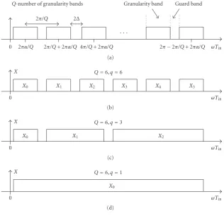
Figure2: Granularity bands and typical input signals.
2.1. Problem formulation
The problem addressed here was outlined in [1] and is based on multiple frequency time division multiple access (MF/TDMA) schemes. The input signal is divided into Q fixed granularity bands. Any user can occupy one or several of these granularity bands. The input signal thus contains
anon-line variable(adjustable) number ofuser subbandsq,
where 1≤q≤Q. In the extreme cases,q=Qandq=1, as illustrated in Figures2(b)and2(d), respectively, forQ=6. The case withq =3 andQ=6 is illustrated inFigure 2(c). It is stressed thatq is anon-line variable and its value can thus be changed during operation by an external controller. In addition, we assumefull flexibilitywhich means that all possible subband decompositions and reallocation schemes can occur. Furthermore, guard bands (transition bands) in frequency are assumed in order to ensure the network to be realizable in practice. This is also depicted inFigure 2. Guard bands are only present between different user subbands, not within a user subband.
The function of the flexible FBR SISO network is thus three-fold: it should (1) separate the input signal into the user subbands, (2) shift the user subbands in frequency to the desired positions, and (3) combine the frequency-shifted user subbands into the output signal. In principle, this function can be implemented through a bank of on-line adjustable-bandwidth filters for the signal separation, and time-varying complex-valued multiplications (modulators)
for the frequency shifts. A straightforward implementation of the adjustable-bandwidth filters and time-varying multi-plications would however result in a very high implementa-tion cost. To solve the problem in a much more efficient way, we propose a new flexible FBR network based on oversam-pled complex-modulated FBs.
2.2. Proposed network
We introduce the flexible FBR SISO network shown in
Figure 3. This scheme makes use of anN-channel analysis filter bank with fixed analysis filters Hk(z) for splitting the input signal intoN subbands, and downsampling and up-sampling byM together with anN-channel synthesis filter bank with adjustable synthesis filters Gk(z) for generating frequency shifts (i.e., redirecting the subbands to the desired output positions) as well as recombination of FB subbands into theqshifted user subbandsyr(n),r =0, 1,. . .,q−1. In the SISO case, all yr(n) are finally summed to produce the single outputy(n), but in the general MIMO case, different yr(n) can be directed to different outputs (seeSection 5).
Fixed analysis FB Adjustable synthesis FB
x(n)
H0(z)
H1(z)
HN 1(z) M
M
M M
M
M
G0(z)
G1(z)
GN 1(z)
Channel
combiner
y0(n)
y1(n)
yq 1(n)
y(n)
. . .
. . .
. . .
. .
. ...
Figure3: Proposed flexible FBR SISO network. The adjustable synthesis FB can be efficiently implemented using a fixed FB and a variable channel switch as indicated inFigure 4.
Flexible frequency-band reallocation network Fixed uniform-band FBs
In
H0(z) H1(z)
HN 1(z) M
M
M
M
M
M
Channel
sw
it
ch
H0(z) H1(z)
HN 1(z) Channel
combiner
μkr y0(n) y1(n)
yq 1(n)
Out .
.
. ... ... ... ... ..
.
Figure4: Efficient implementation of the proposed flexible FBR SISO network inFigure 3using a fixed FB and a variable channel switch. With an appropriately chosen prototype filter order, allμkrbecome equal to unity.
function using instead a variable channel switch and fixed FBs according to the proposed scheme inFigure 4where the output from the analysis filterHk(z) is connected to the in-put of the synthesis filter Hckr(z), with ckr being given by (16) andμkrbeing adjustable phase rotations given by (17) in
Section 2.5. In this way, the complexity can be reduced sub-stantially, as fixed filters are considerably less complex to im-plement in hardware compared to adjustable filters. Further-more, the fixed analysis (synthesis) FB can be implemented using only one filter block and an IDFT (DFT) block, and all μkrbecome unity for an appropriately chosen filter order. In
all, this results in a very efficient realization with retained full flexibility. The key to this efficient solution is to make use of oversampling to avoid channel aliasing, more channels than granularity bands, and appropriately matched analysis and synthesis filters. The following sections give the details.
2.3. Restrictions onMandN
As opposed to fixed networks, aliasing components cannot be completely eliminated through cancellation in fully flex-ible FBR networks due to the large number of reallocation possibilities and constraints. Instead it must be possible to make them arbitrarily small in each channel which can be done using oversampling FBs and analysis filters with high
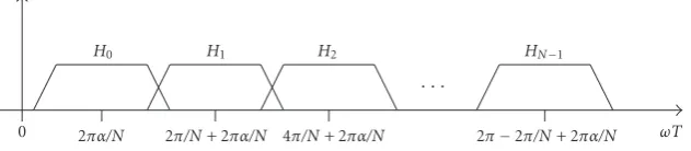
enough stopband attenuation. To ensure this in the present setup, it is first observed that the filters are to extract spectra in accordance with Figures2and5. This is achieved by divid-ing each granularity band into a number of uniform-band FB channels with principle filter magnitude responses according toFigure 6(also cf. the discussion below). The filter band-widths are thus 2π/Nand their transition bands are 2Δwide. It is now required that passbands and transition bands of shifted terms caused by decimation do not overlap. This is achieved when
M≤ N
1 +NΔ/π < N. (1) In addition to the constraint in (1), there is an addi-tional relation betweenMandN that must be fulfilled and it is derived as follows. Through decimation and interpola-tion by the factorM, frequency shifts of 2πm/Mradians for m=0, 1,. . .,M−1 can be generated. It is required that one is able to generate all integer frequency shifts of the granu-larity frequency shift, that is, all frequency shifts 2πq/Qfor q=0, 1,. . .,Q−1. In particular, one must be able to shift the granularity bands by all values 2πq/Q. It is therefore required thatMbe a multiple ofQ, that is,
X0 X1 X2
2π
0 ωT
(a)
2π
0 ωT
H0 H1 H2 H3 H4 H5 H6 H7
(b)
2π
0 ωT
G0 G1 G2 G3 G4 G5 G6 G7
(c)
Y0 Y1 Y2
2π
0 ωT
H0G0+H1G1 H2G2+H3G3+H4G4+H5G5 H6G6+H7G7
(d)
2π
0 ωT
G2 G3 G4 G5 G6 G7 G0 G1
(e)
Y1 Y2 Y0
2π
0 ωT
H3
0G0+H13G1 H3
2G2+H33G3+H43G4+H53G5 H63G6+H73G7
(f)
Figure5: Illustration of frequency-band reallocation using the proposed FBs withQ=4,N =8. (a)–(d) Recombination of channels. (a), (b), (e), and (f) Recombination of channels and reallocation of subbands;H3stands forHshifted three granularity-band shifts to the right which amounts to one shift to the left whenM=4.
SinceN > Maccording to (1), this means that the number of uniform-band channels cannot equal the number of granu-larity bands. Instead,Nmust be a multiple ofQ, as illustrated inFigure 5. That is,
N=AQ=AMB , A > B,Ainteger. (3)
Because the downsampling-by-Mblocks (upsampling-by-M blocks) inFigure 4can be propagated to the input (output) [9], the complexity for a givenN is minimized by selecting M as large as possible without introducing aliasing, that is, without violating (1). Thus, it follows from (2) and (3) that
Bis selected as
B=A−K, 1≤K≤A−1,Kinteger, (4)
whereby
M=N−KQ, (5)
whereKis the smallest integer allowed without introducing aliasing. From (1) and (5), it follows thatKmust satisfy
K≥Q εN2 (Q+εN) =
εA2
1 +εA, (6)
0 ωT
H0 H1 H2 HN 1
2πα/N 2π/N+ 2πα/N 4π/N+ 2πα/N 2π 2π/N+ 2πα/N
Figure6: Principle magnitude responses of the analysis filters.
granularity band 2π/Q, that is,
2Δ=ε2Qπ, 0< ε≤1. (7)
For any givenQ, one can thus in principle choose any value of N[which also determinesM through (5)] satisfy-ing (2) and (3). In practice, it is selected so as to minimize the implementation complexity. This issue will be treated in
Section 3.
Discussion
As seen in (3), the new network makes use of more FB chan-nels than granularity bands (maximum number of user sub-bands). This is necessary in order to be able to generate all possible frequency shifts, the reason being that a slight over-sampling is employed. At first sight, this may seem to be a drawback but is in fact an advantage in that the implementa-tion complexity can be reduced by using more channels than the minimum one required by the application, which isQin the present application. It is possible to useN > Qhere (but not in all FB applications) because the role of the FB is to move spectra which one in principle can do with an arbitrary number of FB channels without degrading the performance in terms of BER, and so forth. In this way, the complexity may even be lower than that of regular maximally decimated FBs despite the fact that a slight oversampling is used.
2.4. Analysis filters
The analysis filters are obtained from a Dth-order linear-phase FIRprototype filterwith transfer function
P(z)=D
n=0
p(n)z−n (8)
and with the impulse responsep(n) being symmetric, that is, p(n)=p(D−n). The frequency response of such a prototype filter can be written as
PejωT=e−jDωT/2P
R(ωT), (9)
wherePR(ωT) is the real zero-phase frequency response [14] andωTdenotes the “discrete-time frequency.” Its magnitude response is here principally as illustrated in Figure 7. The analysis filters are complex-modulated versions of the pro-totype filter according to
Hk(z)=βkPzWNk+α, k=0, 1,. . .,N−1, (10)
π
P
π/N 0 π/N π ωT
2Δ
Figure7: Principle magnitude response of the prototype filter.
where
WN =e−j2π/N, (11) βk=WN(k+α)D/2, (12)
andαis a real-valued constant used for placing the filters at the desired centre frequencies according to Figures2and5.
The constants βk compensate for the phase rotations that generally are introduced when replacing theDth-order linear-phase FIR filterP(z) with P(zWNk+α). In this way, all analysis filters become linear-phase FIR filters with the same delay (D/2) as the prototype filter. Indeed, withβkas in (12), the frequency responses become
HkejωT=e−jDωT/2PR
ωT−2π(kN+α)
. (13)
2.5. Synthesis filters
As opposed to conventional FBs, where one is interested in perfect reconstruction of the inputx(n), the synthesis filters must here be chosen in such a way that the outputs yr(n), r=0, 1,. . .,q−1, ideally are frequency-shifted (and delayed due to the FB delay) versions of the subsignals according to
Yr(z)=z−DXrzWsr
Q, (14)
whereWQ=e−j2π/Q, 2π/Qis the granularity frequency shift
(minimum allowed frequency shift), andsris an integer de-noting the desired number ofgranularity-band shiftsof sub-band r. For example, if it is desired to move X0 (X2) in
Figure 2(b)to the position ofX2(X0), thensr=2 (sr= −2). Furthermore, it should be possible to approximate perfect FBR as close as desired (i.e., to approximate (14) as close as desired) for all values ofq, 1≤q≤Q, by properly designing the FB. Both of these criteria are met by selecting the synthe-sis filters as
where
ckr=k+Asr, (16) μkr=WN(mrN/M)D/2 (17)
with
mr=
⎧ ⎨ ⎩
Bsr, sr≥0,
M+Bsr, sr<0, (18)
andBbeing given by (4). The equations above hold fork = Air,Air+ 1,. . .,Air+Anr−1, withirdenoting the left-most granularity band included inxr(n),Abeing given by (3), and nr denoting the number of granularity bands in subbandr.
To obtain (17), we have utilized that Wmr
M =WNmrN/M. (19)
It should be noted here that the pair (k,r) only takes on values that correspond tockr ∈ [0,N−1] which for obvi-ous reasons must be ensured. This will always be the case because our notations reflect the fact that the input sub-bandrcovering the granularity-band positionsi, fori =ir, ir+ 1,. . .,ir+nr−1, is to be moved to the positionsi+sr. That is, it is a priori assumed that
ir,ir+nr−1∈[0,Q−1] (20)
as well as
ir+sr,ir+sr+nr−1∈[0,Q−1]. (21)
Since the number of FB channels isN=AQ, it follows that the input subbandris also covered by the analysis FB chan-nelsk, fork=Air,Air+ 1,. . .,Air+Anr−1. For these values
ofk, it now follows from (20) that
k+Asr∈0,A(Q−1) +A−1=[0,N−1]. (22)
Thus, allckrin (16) belong to [0,N−1].
The constants μkr compensate for the phase rotations that generally are introduced when replacing theDth-order linear-phase FIR filtersHk(z) withHk(zWmr
M). In this way, all
synthesis filters become linear-phase FIR filters with the same delay (D/2) as the prototype filter (compare with the analysis filters inSection 2.4). Further simplifications are obtained by noting that it is always possible to make allμkr =1. Indeed, we have
mrD
2M =integer=⇒μkr=1. (23) Thus, it is always possible to make allμkr equal to unity by selecting the filter orderDof the prototype filter properly. This is easily achieved by introducing a proper amount of additional delays.
Finally, it is noted that it follows from (15) that the net-work inFigure 3with fixed filters and adjustable filters can be efficiently implemented by the network inFigure 4that uses two sets of fixed filters and a variable channel switch.
80 60 40 20 0
Hk
(
e
jω
T)(
d
B
)
0 0.4π 0.8π 1.2π 1.6π 2π
ωT(rad)
Figure8: Analysis filters inExample 1.
60 40 20 0 20
X
(
e
jω
T)(
d
B
)
0 0.4π 0.8π 1.2π 1.6π 2π
ωT(rad)
X0 X1 X2
Figure9: Input spectrum inExample 1.
Example 1. As a means of illustration, we consider the
following example:
Number of granularity bands: Q=4 Number of FB channels: N=8 Downsampling factor: M=4
Transition band width: Δ=0.125π/Q=0.125π/4 Frequency offset: α=0.5
Prototype filter order: D=134 Number of subbands: q=3 Number of granularity bands
in each input subband: n0=1,n1=2,n2=1 First FB channel in each
input subband: k0=0,k1=2,k2=6. The magnitude responses of the analysis filters are shown inFigure 8. Design details will be discussed inSection 4. The input spectrum is plotted inFigure 9. We now consider three different reallocation schemes.
Reallocation scheme (a)
60 40 20 0 20
Y
(
e
jω
T)(
d
B
)
0 0.4π 0.8π 1.2π 1.6π 2π
ωT(rad)
Y0 Y1 Y2
Figure10: Output spectrum inExample 1for reallocation scheme (a).
60 40 20 0 20
Y
(
e
jω
T)(
d
B
)
0 0.4π 0.8π 1.2π 1.6π 2π
ωT(rad)
Y1 Y2 Y0
Figure11: Output spectrum inExample 1for reallocation scheme (b).
normalized so that the signal has a unity average power. Us-ing an additional filter for recoverUs-ing the first subband (x0), we find that the maximum distance between the input and output samples is below 0.01. As a consequence, if the sym-bol error rate due to additive white noise alone (thus with-out errors created in the FBR network) is, say, 10−6, it will in the worst case be increased to 1.5×10⁻⁶due to the FBR net-work. By increasing the filter orders, and redesigning the FBR network, the degradation can be reduced to any level that in practice is negligible.
Reallocation scheme (b)
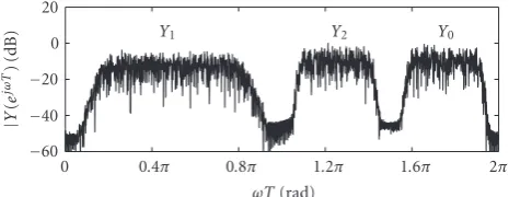
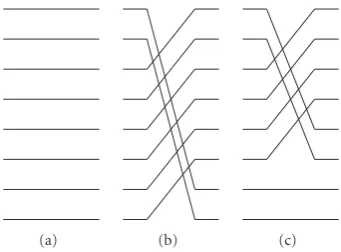
In this case, we assume a scheme as that shown earlier in Figures5(a),5(b),5(e), and5(f). This is achieved by select-ing the synthesis filters accordselect-ing to (15) with the following numbers of granularity-band shifts:s0 = 3,s1 = s2 = −1. These values imply thatmr =3, forr =0, 1, 2, which means thatμkr= −jfor all pairs of valueskrof interest in (17), that is, forkr=00, 10, 21, 31, 41, 51, 62, 72. These values ofkr re-sult in the following values ofckr:c00 =6,c10 =7,c21 =0, c31=1,c41=2,c51=3,c62=4,c72=5. When the synthesis FB is implemented using a switch and fixed filters, as shown inFigure 4, we recall that the role of the channel switch is to redirect its input at positionkto its output at positionckr. In this example, the switch inFigure 4is thus implemented as shown inFigure 13(b). The output spectrum becomes as shown inFigure 11. The errors are of the same order as in scheme (a).
Reallocation scheme (c)
In this case, we assume that the two narrow-band subbands are to interchange their positions as compared to scheme (b).
60 40 20 0 20
Y
(
e
jω
T)(
d
B
)
0 0.4π 0.8π 1.2π 1.6π 2π
ωT(rad)
Y1 Y0 Y2
Figure12: Output spectrum inExample 1for reallocation scheme (c).
The output spectrum becomes in this case as shown in
Figure 12. The errors are of the same order as in schemes (a) and (b). The parameter values are here as follows: s0 = 2, s1 = −1,s2 = 0;m0 = 2, m1 = −1,m2 = 0;c00 = 4, c10 = 5, c21 = 0, c31 = 1, c41 = 2, c51 = 3,c62 = 6, c72 = 7;μ00 = μ10 = −1,μ21 = μ31 = μ41 = μ51 = −j, μ62 = μ72 = 1. The switch is in this case implemented as shown inFigure 13(c).
Finally, it is noted that we used a filter order of 134 in this example which resulted in multiplier valuesμkr not equal to unity. This was done in order to illustrate that the proposed technique works in such cases as well. By increasing the filter order to, for example, 136, allμkrbecome equal to unity.
3. IMPLEMENTATION COMPLEXITY
The main point of this section is the selection of the number of FB channelsNthat minimize the overall implementation complexity when efficient DFT- and IDFT-based realizations are employed.
3.1. Efficient DFT- and IDFT-based realizations
Utilizing the polyphase form ofP(z) given by [9]
P(z)=N −1
i=0
z−iP
izN, (24)
wherePi(z) are the polyphase components,Hk(z) in (10) can be rewritten as
Hk(z)=βk
N−1
i=0
z−iαiPizNWαN N
W−ki
N , (25)
where
αi=WN−αi. (26)
Making use of (25), well-known properties of DFT and IDFT FBs, and properties of downsamplers and upsamplers, it is now recognized that the analysis and synthesis FBs can be re-alized with the aid of anN-point IDFT andN-point DFT, re-spectively, as shown in Figures14and15where all arithmetic operations take place at the lowest sampling rate (fin/M). The multipliers inFigure 15are given by
(a) (b) (c)
Figure13: Channel switch inExample 1; Schemes (a), (b), and (c).
In the efficient synthesis FB inFigure 15, the separate outputs yr(n) from the channel combiner (Figure 3) are not available.
This means that the multipliersμkr have to be placed at the input, preferably in front of the DFT (instead of the channel switch) since they can then be combined with the multipliers already present there; this is illustrated inFigure 15. In this way, the multiplier cost can be minimized also in those cases whenμkr =/ 1. It should also be noted that not having the separate outputsyr(n) available is not a problem in the SISO case as only the composite outputy(n) is supposed to be used here. However, in the MIMO case, this is a problem that must be taken care of (seeSection 5).
In summary, it is seen that the proposed FBR network has about the same low complexity as that of a regular fixed mod-ulated FB but with the additional inherent flexibility. Natu-rally, there is an overhead cost due to the channel switch, but such a block is required in all flexible FBR networks and thus not an extra cost in comparison with other such networks.
3.2. Selection ofNthat minimizes the implementation complexity
As seen earlier inSection 2.3, there is not just one selection of the number of FB channelsNthat can be used for a fixed prespecified number of subbandsQand guard band width 2Δ. In practice, it is of course of interest to selectNso that the overall implementation complexity is minimized. This issue is treated in this section.
Because the prototype filterP(z) is a linear-phase FIR fil-ter, its orderDcan be estimated as [15]
D= Kp
2Δ, (28)
where 2Δ is the transition bandwidth (which equals the width of the guard band, seeFigure 2) and
Kp=−20 log10
δcδs−13
14.6/(2π) (29) withδcandδsbeing the passband and stopband ripples, re-spectively. The order is thus inversely proportional to the transition bandwidth. The number of multipliers required in the prototype filter isD+ 1, since the symmetry of the linear-phase FIR prototype filter cannot be utilized. Further,
the implementation of anN-point DFT, as well as an IDFT, requires about 0.5Nlog2(N) multiplications per block ofN input/output samples, provided that an efficient FFT algo-rithm is used. The complexityCAof the analysis FB becomes thereby1,2
CA=D+ 1 + 0.M5Nlog2(N)
=KP/Δ+ 2 +Nlog2(N)
2M .
(30)
For a fixedN, it is evident from (30) that the complexity re-duces asMincreases. This justifies the choiceM=N−KQ in (5) inSection 2.3. Expressed in terms ofA, withN=AQ according to (3), (30) can alternatively be written as
CA=KP/Δ+ 2 +2AQM log2(AQ). (31)
Assuming that equality holds in (1) and (6), one may find the minimum of the functionCAby setting its derivative with re-spect toAto zero and solve forAyielding the optimumA, denoted here asAopt. However, since CA and its derivative involve bothAand the logarithm ofA, it is not possible to expressAoptin a simple form. In practice it is therefore advis-able to plotCAas a function ofAfrom whichAopteasily can be identified. This is illustrated inFigure 16for two different values ofKP. One should note here that there are basically three different cases that may occur. In the first case, as seen in the uppermost plot in Figure 16,Aopt lies between Amin andAmax, which denote the minimum and maximum values ofA, respectively. The minimum value is alwaysAmin = 2 due to (2) and (3). The maximum value is determined by the upper bound onNthat exists because the number of chan-nels (N/Q) in each subband times the guard bandwidth (2Δ) cannot exceed the granularity bandwidth (2π/Q).3Hence,N is bounded by
N≤ π
Δ =Qε, (32) where the equality comes from (7). This implies that the maximum value ofAis
Amax=
1 ε
, (33)
wherexstands for the maximum integer smaller than or equal tox. In the second case, as seen in the downmost plot inFigure 16,Aopt =Amax. This occurs whenKP is large. In
the third case,Aopt=Amin, which occurs whenKPis small.
1As a measure of complexity, the multiplication rate is used. It is here the
number of multiplications per input (output) sample in the analysis FB (synthesis FB). The multiplication rate takes into account the data rate at which the multiplications are performed.
2The number of additions and delay elements is here roughly proportional
to the number of multiplications and is therefore omitted in the discus-sion.
3The bound can be increased, in principle to infinity, by reducing the guard
x(n) M
M
M z 1
z 1
P0(zLWNαN)
P1(zLWNαN)
PN 1(zLWNαN)
α0
α1
αN 1
. . .
. . .
IDFT
β0
β1
βN 1
Figure14: Analysis FB realizing the analysis filtersHk(z), as given by (10), whereL = A/B = integer. WhenA/Bis not an integer, a
more general polyphase implementation of the polyphase componentsPi(zN) followed by downsampling has to be used [9], but all filtering
operations can still be moved to the input rate.
y(n)
M M M
z 1
z 1 PN 1(zLWNαN)
PN 2(zLWNαN)
P0(zLWNαN)
α0 αN 2 αN 1
. . .
. . .
. . .
. . . DFT
γ0
γ1
γN 1 μkr
Channel
sw
it
ch
Figure15: Synthesis FB realizing the synthesis filtersGk(z) as given by (15) using a channel switch and fixed filtersHk(z) as given by (10).
10 12 14 16
Com
p
le
xi
ty
CA
1 2 3 4 5 6 7 8 9 10 11
A=N/Q Amin=2
KP=11.62
Amax=10
(a)
10 20 30 40
Com
p
le
xi
ty
CA
1 2 3 4 5 6 7 8 9 10 11
A=N/Q Amin=2
KP=33.14
Amax=10
(b)
Figure16: ComplexityCAas a function ofA=N/Qfor two diff
er-ent values ofKPas given by (29).
In the discussion above, some simplifications were made in order to arrive at the optimumA. In practice, there are several issues that must be taken into consideration which complicates the minimization of the complexity. These issues are discussed below.
First, it was assumed that the passband and stopband ripples are constant regardless the value of N. As N in-creases, one should rather replace the stopband rippleδsby δs/N though, to compensate for the larger number of alias-ing components, at least when usalias-ing worst-case design tech-niques (see (49) inSection 4.3). However, since the order of an FIR filter depends on the stopband ripple logarithmically, this compensation will have a minor effect upon the order. Hence, if we instead useδs/N above, the complexityCAas a function ofAwill only change slightly.
Second, it was assumed that the prototype filter is a reg-ular lowpass linear-phase FIR filter without requirements in the transition band. However, one should compensate for the fact that the prototype filter must exhibit an approximately power complementary behavior in the transition band. This means that the constantKP in (28) should be replaced by cKP,c >1. Our experience is thatcis approximately constant,
designs that confirm this assertion. Ifcis constant, the effect is that we simply increase the value ofKP, the result of which is that Aopt will move closer to Amax, unless Aopt = Amax forKPin which caseAoptremains the same. This is seen in
Figure 16.
Third, we have assumed that all multiplications have the same cost in an implementation. However, in cases where α takes on the value 0, ±0.25, or ±0.5 (implying that WN−αN takes on the values 1, ±j, and −1) each mul-tiplication in the polyphase components only requires one real multiplication whereas the multiplications in the DFT and IDFT, most of which are always complex, require at least three real multiplications [16]. Taking this into ac-count amounts to replacing 0.5 in (30) with 1.5, the re-sult of which is that Aopt will move closer toAmin, unless Aopt = Amin for the value 0.5, in which caseAopt remains the same.
Taking these issues into account, one can thus still gener-ate a plot as that inFigure 16from which the optimum value ofAcan be determined. As to the synthesis FB, its complex-ity is the same as that of the analysis FB when allμkr equal unity, which always can be guaranteed if a certain amount of additional delay can be accepted. In the most general case, with some or all ofμkrnot being equal to unity, at mostN/M additional complex multiplications per input/output sample are required. SinceN/M never exceeds 1/2, this is a minor extra cost during normal operation.
4. DESIGN
This section considers the design of the flexible FBR net-work which amounts to determining the linear-phase FIR prototype filterP(z) so that the network approximates per-fect FBR. This is in principle the same design problem as in conventional FBs, but it is much more complex here due to the many different reallocation schemes involved.
4.1. Distortion and aliasing
Using well-known input-output relations for the downsam-pler and upsamdownsam-pler [9], one finds that thez-transform of the outputy(n) in Figures3and4can be expressed as
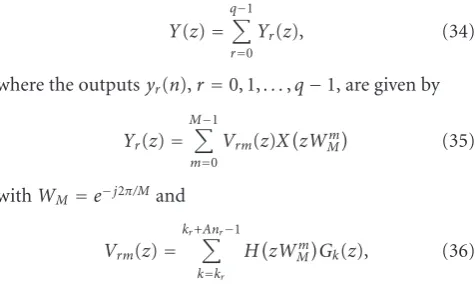
Y(z)=
q−1
r=0
Yr(z), (34)
where the outputsyr(n),r=0, 1,. . .,q−1, are given by
Yr(z)=
M−1
m=0
Vrm(z)XzWMm (35)
withWM=e−j2π/Mand
Vrm(z)=
kr+Anr−1
k=kr
HzWm
MGk(z), (36)
wherekr =Airdenotes the first FB channel included in the same band asxr(n). We now wish to state the condition un-der which perfect FBR is obtained. In orun-der to do that in a
simple form, we first recognize that (14) in the Fourier do-main corresponds to
YrejωT=e−jDωTXrejωTWQsr (37)
which, equivalently, can be written as
YrejωT=FrejωTWQsrXejωTWQsr (38)
with
FrejωT=
⎧ ⎨ ⎩
e−jDωT, ωT∈Ω(r)
x ,
0, ωT /∈Ω(r)
x , (39)
where
Ωr
x=2ir−1π/Q+ 2πα/Q+Δ,
2ir+ 2nr−1π/Q+ 2πα/Q−Δ (40)
and 1/Tis the input and output sampling rate.
The network is a perfect FBR network if the right-hand side of (35) forz =ejωT equals that in (38). Thus, the
net-work is a perfect FBR netnet-work ifVrm(z) in (36) for allrand msatisfy
VrmejωT=FrejωTWQsr, m=mr,
Vrm(z)=0, m=/ mr, (41)
whereFr(ejωT) is given by (39) andmris given by (18). We have also utilized thatWsr
Q =WMmr. Whensr is negative,mr
equalsM+Bsrinstead ofBsrwhich is due to the fact that only positive values ofmare used in (35). It is possible to replace BsrwithM+BsrbecauseWMm=WMM+m.
It should be noted that for the special case withq=Q= 1, a regular FB is obtained. In this case, no reallocation can take place (since only one band is present) and the whole band should be reconstructed. In this special case, a perfect FBR is the same as a perfect reconstruction FB.
4.2. Relation betweenVrmr(ejωT)andVr0(ejωT)
This section shows that the FBR network for allsrof interest can be related to an FBR network withsr =0, that is, when subbands are not reallocated but only recombined. This amounts to showing that Vrmr(ejωT) are frequency shifted versions ofVr0(ejωT). This relation eases the design substan-tially as discussed in the following section.
We first note that the frequency responses correspond-ing toHk(zWMmr) andGk(z) are obtained from (9), (10), and (15), as
HkejωTWMmr
=e−jDωT/2W−(mrN/M)D/2
N
×PR
ωT−2π
k+mrN/M+α N
,
GkejωT=e−jDωT/2WN(mrN/M)D/2
×PR
ωT−2π
k+mrN/M+α N
,
respectively. Hence, the frequency responses corresponding toVrmr(z)=Hk(zWMmr)Gk(z) become
Vrmr
ejωT
=e−jDωTkr+Ani−1
k=kr
P2
R
ωT−2π
k+mrN/M+α N
.
(43)
Thus, the distortion function is a linear-phase function with delayDand magnitude
Vrmr
ejωT=kr+Ani−1
k=kr
P2
R
ωT−2π
k+mrN/M+α N
.
(44)
We note that Vrmr
ejωT=V
r0
ejωTWmrN/M
N
, (45)
whereVr0(ejωT) is given by
Vr0
ejωT=e−jDωTkr+Ani−1
k=kr
P2
R
ωT−2π(kN+α)
, (46)
is the distortion function when the subbands are only re-combined (thus not reallocated). This shows thatVrmr(z) are
frequency-shifted versions ofVr0(z). Hence, if the network is a near-perfect FBR network whenGk(z)= Hk(z), so is the
network when theseGk(z) are replaced with the functions in (15). It should be mentioned, however, that the aliasing com-ponents do not remain the same but their magnitudes are still bounded by the stopband attenuation of the prototype filter.
4.3. Minimax design
Filter banks are commonly designed using minimax or least-squares design techniques, or combinations of such design techniques [17]. This paper discusses minimax design but the alternatives can of course be used as well after appropriate modifications.
Due to (45), it suffices to controlVr0(ejωT), given by (46), forr =0, 1,. . .,q−1, and the aliasing terms in the design. For this reason, let the specifications ofVrm(z) be
Vr0
ejωT−FrejωT≤δ0, ωT∈[0,π], (47)
whereδ0>0 andFr(ejωT) is given by (39), and Vrm
ejωT≤δ
1, ωT∈[0,π], (48)
form = 0, 1,. . .,M−1,m =/ mr,mr being given by (18),
andδ1>0. The parametersδ0andδ1are prescribed distor-tion and aliasing errors, respectively, and determined by the application at hand. In conventional FBs, the distortion and aliasing errors can be made zero by using certain classes of PR FBs. It is however not likely that one can find practical
realizations with zero distortion and aliasing errors when it comes to flexible FBR reallocation networks. The reason is that (41) should be satisfied for all r = 0, 1,. . .,q−1, all q=0, 1,. . .,Q−1, and all feasible combinations and reallo-cations schemes. This means that the number of conditions to satisfy is substantially larger for flexible FBR networks than for regular FBs. Therefore, one has to accept the use of near-perfect FBR networks. This is however not really a problem because the FB is to be used in a communication system which always contains other sources of errors which together result in a certain BER. The important point is that it is pos-sible to design the FBR network to approximate perfect FBR as close as desired as one thereby can make the degradation due to the imperfect FBR network negligible compared to the other errors involved. In addition, it is known that the use of near-PR FBs instead of PR FBs can reduce the complex-ity substantially [17] which means that one should aim for near-PR systems anyhow. Exactly how close to perfect FBR the network must be is not specific for the proposed network but depends on the communication environment, modula-tion techniques, and other factors [18] that are beyond the scope of this paper.
In principle, one can apply any standard nonlinear opti-mization technique [19] directly to meet the criteria in (47) and (48). However, as the optimization is nonlinear, and will contain many constraints, it may become numerically diffi -cult or infeasible to solve this problem in practice. One way to reduce the number of constraints substantially is to allow a slight overdesign and replace (48) with
P
ejωT≤δ1
N, ωT∈Ωs, (49) whereΩsdenotes the stopband ofP(z). It is also noted that nonlinear optimization benefits from a good initial solution which here can be obtained by using the well-known algo-rithm in [20] which generates linear-phase FIR filters opti-mum in the minimax sense.
Finally, we note that, for a fixed reallocation scheme, (47) and (48) correspond to the requirements of partially recon-structing FBs [7]. However, as already explained, the design problem is much more complex here as a large number of reallocations options must be handled simultaneously in the design.
5. FLEXIBLE FBR MIMO NETWORKS
This section shows how to generalize the proposed SISO net-works to MIMO netnet-works.
5.1. K-inputK-output frequency-band reallocation networks
Frequency-band reallocation network
In 1
In 2
InK
Out 1
Out 2
OutK AFB
AFB
AFB
SFB
SFB
SFB .
. .
. . .
. . .
. . .
Channel
sw
it
ch
Fixed filter banks
Figure17: ProposedK-inputK-output flexible FBR network using fixed FBs and a channel switch.
60 40 20 0 20
X1
(
e
jω
T)(
d
B
)
0 0.4π 0.8π 1.2π 1.6π 2π
ωT(rad)
X10 X11 X12
Figure18: Input 1 spectrum inExample 2.
switch in this MIMO case is able to redirect information from any input beam to any output beam, as illustrated in the example below. If the FBR SISO network is designed as outlined inSection 4, the overall performance for each out-put subband in the MIMO network will be the same as in the SISO network, except for some minor negligible differences caused by differences in the aliasing terms. Consequently, it suffices to design one prototype filter for the SISO case, that is, as outlined inSection 4, and then useKinstances of the corresponding FBs according toFigure 17. This implies that the proposed MIMO system is modular which is attractive from the design and implementation points of view.
Example 2. The function of the proposed FBR MIMO
net-work is illustrated through an example with two input and output beams. The two input spectra are plotted in Figures
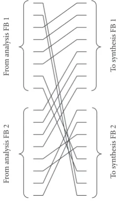
18and19. It is desired to reallocate the subbands according to Figures20and21, which plot the two output spectra. The frequency-band reallocation is achieved by using the channel switch inFigure 22and FBs with the same filter magnitude responses as used earlier inExample 1(Figure 8), but with an additional filter delay introduced to make allμkrequal to unity.
60 40 20 0 20
X2
(
e
jω
T)(
d
B
)
0 0.4π 0.8π 1.2π 1.6π 2π
ωT(rad)
X20 X21 X22
Figure19: Input 2 spectrum inExample 2.
60 40 20 0 20
Y1
(
e
jω
T)(
d
B
)
0 0.4π 0.8π 1.2π 1.6π 2π
ωT(rad)
Y11 Y20
Figure20: Output 1 spectrum inExample 2.
60 40 20 0 20
Y2
(
e
jω
T)(
d
B
)
0 0.4π 0.8π 1.2π 1.6π 2π
ωT(rad)
Y10 Y12 Y22 Y21
Figure21: Output 2 spectrum inExample 2.
Fro
m
an
al
ys
is
F
B
2
Fro
m
an
al
ys
is
F
B
1
T
o
synthesis
F
B
2
T
o
synthesis
F
B
1
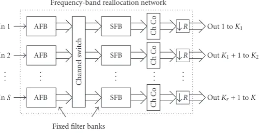
Frequency-band reallocation network In 1
In 2
InS
Out 1 toK1
OutK1+ 1 toK2
OutKr+ 1 toK AFB
AFB
AFB
SFB
SFB
SFB .
. .
. . .
. . .
. . . . . .
Channel
sw
it
ch
Fixed filter banks
Ch
Co
Ch
Co
Ch
Co
R
R
R
Figure23: ProposedS-inputK-output FBR network using fixed FBs, a channel switch, and channel combiners (Ch Co).
5.2. S-inputK-output systems
Generalizing theK-inputK-output system considered above to anS-inputK-output system, we propose the flexible FBR network depicted inFigure 23. Again, it is assumed that the subbands are reallocated to unique positions which implies thatK≥S. It is further assumed that
K=RS (50)
which corresponds to the fact that the output beams’ band-width is assumed to beR times narrower than that of the input beams4. This means that only some of the synthesis FB outputs are combined to form the outputs. It also means that decimation byRcan take place at the outputs without introducing aliasing. Hence, in principle, it is again possible to use onlySfixed synthesis FBs, but it is then not possible to directly redirect all output subbands to the baseband. In-stead, one has to make use of the whole band and let the sub-sequent decimation make the mapping to the baseband; that is, the spectrum at the input of each decimator has a band-width ofπ/Rand is positioned betweenpπ/Rand (p+ 1)π/R with respect to the input sampling rate, withpbeing an inte-ger belonging to the set [0,R−1].
However, a problem of using onlySfixed synthesis FBs is that it is then not possible to make use of the efficient realization in Figure 15because the outputs of the synthe-sis filters are not available in that structure. To get around this problem, we propose to use insteadK = RSfixed syn-thesis FBs, each being an instance of the fixed synsyn-thesis FB used inSection 3(Figure 15) but with some of the inputs to the DFT being zero which corresponds to the fact that only a subset of the FB channels will be utilized in each synthesis
4This case can be generalized to allow outputs with different data rates
which amounts to allowing different downsampling factors at the output inFigure 23. In the implementation, different instances of synthesis FBs must then be used, with different numbers of inputs to the DFT being set to zero.
FB (See Footnote 4). In this case, one can redirect all out-put subbands to the baseband. Further, by making use of multirate identities [9] one can make the overall computa-tional complexity of the K synthesis FBs roughly the same as earlier. That is, the number of arithmetic operations per time unit remains the same whereas the number of synthe-sis FB instances isRtimes higher. Note that analysis FBs can be implemented in the same way as for the SISO case and MIMO case with equal number of inputs and outputs. It is thus only the synthesis parts that need to be modified in this generalized MIMO case.
5.3. Further generalizations
One may also think of allowing S > K in the network in
Section 5.2above. However, this requires synthesis FBs with upsampling rates higher than the downsampling rates used in the analysis FBs. The proposed network cannot be used for this case straightforwardly and is therefore not discussed further in this paper.
6. CONCLUDING REMARKS
REFERENCES
[1] B. Arbesser-Rastburg, R. Bellini, F. Coromina, et al., “R&D di-rections for next generation broadband multimedia systems: an ESA perspective,” inProceedings of 20th AIAA International Communication Satellite Systems Conference and Exhibit, Mon-treal, Quebec, Canada, May 2002.
[2] E. Del Re and L. Pierucci, “Next-generation mobile satellite networks,”IEEE Communications Magazine, vol. 40, no. 9, pp. 150–159, 2002.
[3] M. Wittig, “Satellite onboard processing for multimedia appli-cations,”IEEE Communications Magazine, vol. 38, no. 6, pp. 134–140, 2000.
[4] M.-L. Boucheret, I. Mortensen, and H. Favaro, “Fast convo-lution filter banks for satellite payloads with on-board pro-cessing,”IEEE Journal on Selected Areas in Communications, vol. 17, no. 2, pp. 238–248, 1999.
[5] G. Chiassarini and G. Gallinaro, “Frequency domain switch-ing: algorithms, performances, implementation aspects,” in
Proceedings of the 7th Tyrrhenian International Workshop on Digital Communications, Viareggio, Italy, September 1995. [6] H. G. G¨ockler and B. Felbecker, “Digital on-board
FDM-demultiplexing without restrictions on channel allocation and bandwidth,” inProceedings of the 7th International Workshop on Digital Signal Processing Techniques for Space Applications (DSP ’99), Noordwijk, The Netherlands, 1999.
[7] T. Q. Nguyen, “Partial spectrum reconstruction using digital filter banks,”IEEE Transactions on Signal Processing, vol. 41, no. 9, pp. 2778–2795, 1993.
[8] W. A. Abu-Al-Saud and G. L. Stuber, “Efficient wideband channelizer for software radio systems using modulated PR filterbanks,”IEEE Transactions on Signal Processing, vol. 52, no. 10, part 1, pp. 2807–2820, 2004.
[9] P. P. Vaidyanathan,Multirate Systems and Filter Banks, Pren-tice-Hall, Englewood Cliffs, NJ, USA, 1993.
[10] P. N. Heller, T. Karp, and T. Q. Nguyen, “A general formula-tion of modulated filter banks,”IEEE Transactions on Signal Processing, vol. 47, no. 4, pp. 986–1002, 1999.
[11] T. Karp and N. J. Fliege, “Modified DFT filter banks with per-fect reconstruction,”IEEE Transactions on Circuits and Systems II: Analog and Digital Signal Processing, vol. 46, no. 11, pp. 1404–1414, 1999.
[12] J. Alhava, A. Viholainen, and M. Renfors, “Efficient imple-mentation of complex exponentially-modulated filter banks,” inProceedings of IEEE International Symposium on Circuits and Systems (ISCAS ’03), vol. 4, pp. 157–160, Bangkok, Thailand, May 2003.
[13] H. Johansson and P. L¨owenborg, “Flexible frequency-band re-allocation network based on variable oversampled complex-modulated filter banks,” inProceedings of IEEE International Conference on Acoustics, Speech and Signal Processing (ICASSP ’05), vol. 3, pp. 973–976, Philadelphia, Pa, USA, March 2005. [14] T. Saram¨aki, “Finite impulse response filter design,” in
Hand-book for Digital Signal Processing, S. K. Mitra and J. F. Kaiser, Eds., chapter 4, pp. 155–277, John Wiley & Sons, New York, NY, USA, 1993.
[15] J. F. Kaiser, “Nonrecursive digital filter design usingI0-sinh window function,” inProceedings of IEEE International Sympo-sium on Circuit and Systems (ISCAS ’74), pp. 20–23, San Fran-cisco, Calif, USA, April 1974.
[16] K. K. Parhi,VLSI Digital Signal Processing Systems: Design and Implementation, chapter 8, John Wiley & Sons, New York, NY, USA, 1999.
[17] T. Saram¨aki and R. Bregovic, “Multirate systems and filter banks,” in Multirate Systems: Design and Applications, G. Jovanovic-Dolecek, Ed., chapter 2, pp. 27–85, Idea Group, Hershey, Pa, USA, 2002.
[18] S. Haykin,Digital Communications, John Wiley & Sons, New York, NY, USA, 1988.
[19] S. G. Nash and A. Sofer,Linear and Nonlinear Programming, McGraw-Hill, New York, NY, USA, 1996.
[20] J. H. McClellan, T. W. Parks, and L. R. Rabiner, “A computer program for designing optimum FIR linear phase digital fil-ters,”IEEE Transactions on Audio and Electroacoustics, vol. 21, no. 6, pp. 506–526, 1973.
H˚akan Johanssonwas born in Kumla, Swe-den, in 1969. He received the Master of Sci-ence degree in computer sciSci-ence and the Li-centiate, Doctoral, and Docent degrees in electronics systems from Link¨oping Univer-sity, Sweden, in 1995, 1997, 1998, and 2001, respectively. During 1998 and 1999 he held a post doctoral position at Signal Processing Laboratory, Tampere University of Technol-ogy, Finland. He is currently a Professor in
electronics systems at the Department of Electrical Engineering of Link¨oping University. His research interests include theory, design, and implementation of signal processing systems. He is the author or coauthor of four textbooks and more than 100 international journal and conference papers. He has served/serves as an Associate Editor for the IEEE Trans. on Circuits and Systems-II (2000-2001), IEEE Signal Processing Letters (2004–2007), and IEEE Trans. Sig-nal Processing (2006–2008), and he is a Member of the IEEE Int. Symp. Circuits. Syst. DSP track committee.
Per L¨owenborgwas born in Oskarshamn, Sweden, in 1974. He received the Master of Science degree in applied physics and electrical engineering and the Licentiate, and Doctoral degrees in electronics sys-tems from Link¨oping University, Sweden, in 1998, 2001, and 2002, respectively. His re-search interests are within the field of the-ory, design, and implementation of analog and digital signal processing electronics. He