Solar Updraft Tower for Energy Generation
Aser Abdelfatah
1High-School Student, Grade-12 Senior Student, STEM High School For Boys -6th October, 6th October, Giza, Egypt
ABSTRACT: The future of this earth and mankind substantially depends on our ability to meet our ever-increasing demand for renewable and environment friendly power sources. Solar energy is one of the prospective solutions; currently, 3 different methods are used to harness solar energy which are photovoltaic solar panels, concentrating solar energy and updraft towers. Updraft is the newest method that both harness solar energy and wind energy. The basic idea uses the concept of chimney effect and green house effect. The base of the solar tower receives solar energy and heats the air inside, decreasing its density and thus evolving in a tower revolving an electric generator inside the tower. The factors affecting the power output of the tower are the area of the base and the length of tower. Updraft tower continue to generate energy at night if the base was supplied by heat sink that absorbs excess heat during day and at night the heat is released. Wind energy can revolve the electric generator if the wind at the base of the tower is strong enough, but the dependency on wind energy is negligible.
KEYWORDS: Energy, Updraft Tower, Solar collector, Chimney effect. I. INTRODUCTION
II. RELATED WORK
The first proposal to the idea of the updraft tower dates back to 1903, but until 1982 there was not any prototype until the first experimental prototype was built in Manzanares, Ciudad Real, 150 km south of Madrid, Spain, but funded by the German government.(Fig. 2) The 195-meters tower could generate up to 50 Kilo watts with 10-meters tower’s diameter and 11-acre solar collector, furthermore the base of the tower was used to grow plants. Since then several research papers were discussing the utility of the tower by several institutions, including MIT, University of Basrah, etc.,and individuals. The previous research paper discussed the working principles, the formulas and laws governing the operation of the tower and the technical details such as the tilt angle of the static solar collector and the direction of the opening in the solar collector as well as the materials that can be utilised for construction whether the extortionate, but expensive fiberglass or the cheap, but non-durable polyethylene. Starting from 2008, several countries showed their interestsin pursuing the construction of a solar updraft tower including Namibia with its proposed 1.5-km ―Greentower‖ and a Spanish 750-meters tower, which was proposed in 2006, but until now no official construction started. The only operated commercial updraft tower is in China, it started operations in 2015. It is producing 200 kilowatts with a 277-hecatres base, and the operating company is planning to build two huge 200-MW towers. Further proposals include building similar towers in the arctic for northern countries and it could yield up to 85% of the desert-built tower.
III.METHODOLOGY
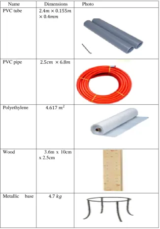
Building Materials are illustrated as follows in figure 3. The PVC tubes were used to construct the 2.4 chimney with 15.5 mm radius. The PVC pipes and the wood were used to construct probes to uphold the prototype. Polyethylene plastic was used as a greenhouse material to cover the solar collector and trap solar energy to heat the air. The metallic base was centred in the middle of the prototype to hold the chimney as will be further illustrated in the next sections.
Name Dimensions Photo PVC tube 2.4𝑚 × 0.155𝑚
× 0.4𝑚𝑚
PVC pipe 2.5𝑐𝑚 × 6.8𝑚
Polyethylene 4.617 𝑚2
Wood 3.6m x 10cm x 2.5cm
Metallic base 4.7 𝑘𝑔
First of all, theproject’s scientific basis was tested using a simulation model based on ―Energy2D‖ softwareas depicted in figure 4. Where the wind energy and solar energy is inserted as inputs and the outputs of the solar updraft tower is the energy generated.
The prototype was made with a one-meter radius base collector and a tower height of 2.4 meters.
1- a professional 3D design for the planned prototype was made using ―Autodesk AutoCAD 2017‖ as shown in (Figure 5). It showed clearly the right dimensions of all the parts and manifested how the idea will be implemented. The chimney is represented by a black tube, the solar base is represented by the circular, green base in the 3D design while the yellow outermost ring is the prob made of PVC pipes and wood.
2- 4 Wooden pieces with dimension (1m * 2.5 cm * 5 cm) are attached in a cross shape as shown in (Figure 6) they are connected with an aluminium extension to form a one wooden, cross-shaped
3- 8 wooden pillars with dimensions (20 cm * 5 cm * 2.5) with an aluminium extension with a hollow place for the PVC electricity coating pipe was attached in the 4 wooden pieces as shown in (Figure 7)
Fig. 4 shows the Engergy2D program design where the 3 fans shows the predicted air flow speed and energy generated
4- The PVC pipe was rounded in the hollow space we made in the pillars (figure 7)
5- The iron base which weighted 4.5 kg was put in thecentre of the wooden cross shape as in (Figure 8)
6- Pieces of wood with dimensions (1.09m × 2.5 cm × 1.25 cm) were attachedbetween the iron base and the rounded PVC pipe and tied it tightly using Iron wires (Figure 9) iron base is connected tightly with PVC pipes
7- We cut a piece of the polyethylene plastic and covered the half of the out layer (rounded part) of the collector then we cut another piece and covered the second half. (Figure 10) this the final step in the tower construction 8- An Electric generator was put in the bottom of the PVC pipe.
Fig.7, wooden pillars were stuck in the ends of the cross shape with PVC tubes Fig.6 the cross shape formed by 4 wooden pieces connected by aluminum extension
Fig..96 wood pieces are connecting the metal base with the rounded PVC tubes.
IV.ANALYSIS&DISCUSSION
The scientific idea: The idea of the updraft tower involves the heating of the air at the base by the collectors like greenhouses then the hot air will rise through the tower revolving a dynamo and generating electricity, while new air will enter the collector instead of the air that flow out which is known as draft, and the flow of air inside the tower is known as stack (chimney) effect ( figure 11). The ground keeps heat to maintain the working of the tower at night
The symbols of the variables and constants used in the equations explaining the working principles of the prototype in figure 12 where each symbol express a certain variable or a certain constant.
Fig..10The final step in covering the solar base with polyethylene
The cross-sectional area of the tower = 𝜋 × 𝑟𝑎𝑑𝑖𝑢𝑠2= 3.14 × 0.7252= 0.016𝑚2± 0.12
velocity of the heated air𝑉 = 2 × 𝑔 × ×𝑇𝑖−𝑇𝑒
𝑇𝑒 =1.046m/sec
Ti and Te are measured where Ti = 316.2 ± 0.3 kelvins and Te = 307.6 ± 0.3 kelvins
The air density: ρi=𝑅 ×𝑇𝑖𝑃 and ρe = 𝑃
𝑅×𝑇𝑒
ρi =1.116 kg/𝑚3, ρe 1.147 kg/𝑚3
the mass flow rate: 𝑚 = 𝐴 × 𝑉 × 𝜌𝑖 = 0.0186 kg/sec
The discharge coefficient: = 𝐶 = 𝑚
𝐴×𝑉×𝜌𝑖= 0.995
Forthe volume flow rate, 2 equations are used𝑄 = 𝐶 × 𝐴 × 𝑉 = 0.0167𝑚3/𝑠, Q=𝑚
𝜌𝑖 =0.0167 𝑚
3/𝑠 that is
the same result
Pressure difference: ∆𝑃 = 𝑔 × × (𝜌𝑒 − 𝜌𝑖)=0.607 pascal
Collector area = area of the cylinder excluding the 2 bases + the area of curved part of the cone=
(2𝜋 × 𝑐𝑜𝑙𝑙𝑒𝑐𝑡𝑜𝑟𝑟𝑎𝑑𝑖𝑢𝑠 × 𝑒𝑖𝑔𝑡𝑜𝑓𝑡𝑒𝑐𝑜𝑙𝑙𝑒𝑐𝑡𝑜𝑟𝑐𝑦𝑙𝑖𝑛𝑑𝑒𝑟) + 𝑐𝑜𝑙𝑙𝑒𝑐𝑡𝑜𝑟𝑟𝑎𝑑𝑖𝑢𝑠 × 𝜋 × 𝑠𝑙𝑎𝑛𝑡𝑒𝑖𝑔𝑡 =
4.617𝑚2± 0.21
The power output: 𝑝𝑜𝑤𝑒𝑟 = ∆𝑃 × 𝐴𝑟𝑒𝑎𝑜𝑓𝑐𝑜𝑙𝑙𝑒𝑐𝑡𝑜𝑟 × 𝑉= 2.93 watts
Power output was calculated in the test plan using the equation 𝑃𝑜𝑤𝑒𝑟 = 𝑝𝑜𝑡𝑒𝑛𝑡𝑖𝑎𝑙𝑑𝑖𝑓𝑓𝑒𝑟𝑒𝑛𝑐𝑒 ×
𝑐𝑢𝑟𝑟𝑒𝑛𝑡𝑖𝑛𝑡𝑒𝑛𝑠𝑖𝑡𝑦
An equation also has been used to get the output power from the temperature difference, the equation is
𝑓 𝑥 = 648√
(𝑥−𝑇𝑒)3 𝑇𝑒
𝑥
And from this equation we got the exact results collected from prototype. V. SIMULATION &RESULTS
Test Plan:
1- Multimeter (a digital instrument that measures potential difference and current intensity) was used to measure the power output. Power output was measured every two hours from 6:00 AM until 9:00 PM for 2 consecutive days.
2-Temperature was measured inside and outside the solar collector by an electronic thermometer. The temperature was measured every 2 hours starting from 6:00 AM to 8:00 PM every two hours forthe same 2 consecutive days.
Results: The power output for the 2 dayswas 3.1 watts an average and the specific results are illustrated in figure 13. The peak is at noon while decreases at night and at morning due to the direct relation with temperature difference
Temperature difference in first day was 8.65 and in second day 8.7.The average of the difference was 8.67. fig. 14 displays the temperature differences for 16 different times. The peak is at noon while decreases at night and at morning
VI.RECOMMENDATIONS
The integration of geothermal energy by introducing a geothermal pump to maintain temperature difference where underground temperature of 50 c° that will be attained at a depth of 1.3 km and water will be circulated through a horizontal pipe at that depth in order to heat the air and increase the temperature difference especially at night and in winter.
VII. CONCLUSION
As demonstrated in the test plan, results and the analysis, it can be concluded how the project satisfied the predicted results, showing results of 3.1 watts as an average of output proving to be renewable, eco-friendly and long durability. Yet, that does not negate the fact that the project is opened to further enhancements included in the recommendations. The project is a prospective alternative to fossil fuels as an eco-friendly energy source utilizing solar energy with negligible assistance from wind.
REFERENCES
[1] Možina, J. College physics: Serway. Pacific Grove, CA: Brooks/cole vol.2, eighth edition, pp. 420-451 2009.
[2] Bob.D. . Bp statistical review of world energy, BP company, 68th ed., pp. 1-52, Rep..2019..
[3] Schlaich, Jörg&Bergermann, Rudolf &Schiel, Wolfgang &Weinrebe, Gerhard. Design of Commercial Solar Updraft Tower Systems—
Utilization of Solar Induced Convective Flows for Power Generation. Journal of Solar Energy Engineering-transactions of The Asme– vol.127, issue 1.pp. 117-124, 2005.
[4] Sungtae P., Energy in Egypt: Background and Issues |American Security Project. Vol. 1, issue 1. 2015
[5] Grose, T. K. Solar Chimneys Can Convert Hot Air to Energy, But Is Funding a Mirage?, National Geographic,2014.
[6] Xinping Z.&Yangyang X., Solar updraft tower power generation, Sol. Energy Science Direct (Vol. 128pp. 95-125, 2014
[7] Boretti, A., & Al-Zubaidy, S.. Maturity assessment of the solar updraft tower technology, Science Direct (Vol. 27)pp. 135-144. 2019
[8] Le C, Solar Updraft Tower Project, MIT Architecture, vol 4. pp. 1-152009
[9] J. S., J. SCHLAICH. SOLAR UPDRAFT TOWERS. Slovak Jounral of Civil Engineering pp.39-42 ,2009
[10] Franz T., Ole L., Helmut K., Solar Electricity Generation – A Comparative view of Technologies, Costs and Environmental Impact, Science
Direct, PP. 89-99, 1997
[11] F.Ayub& A. S. Khan&Saarah A.& G. SaklayenDesign and Fabrication of Solar Updraft Tower and Estimation of Power Generation; Initially
Focused on Bangladesh, IOP Conference Series Earth and Environmental Science, pp 1-6. 2018.
[12] P. J. Bansod, S. B. Thakre, N. A Wankhade, Solar Chimney Power Plant – A Review, International Journal of Modern Engineering Research