ISSN(Online): 2319-8753 ISSN (Print): 2347-6710
I
nternational
J
ournal of
I
nnovative
R
esearch in
S
cience,
E
ngineering and
T
echnology
(A High Impact Factor, Monthly, Peer Reviewed Journal)
Visit: www.ijirset.com
Vol. 8, Issue 10, October 2019
A Survey on Low Cost Function Generator
for Stepper Motor
Chinelo R. Anene
1, Onyeka A. Ikenga
1Lecturer, Department of Physics and Industrial Physics, Nnamdi Azikiwe University Awka, Nigeria1
ABSTRACT: Function generator plays a very important role in electronic circuits, communication, control, and other electronic systems. This paper describes the design and implementation of low-cost waveform generator using a 555 timer and 4017 Decade counter. The signal generated is tested with stepper motor driver thus making it viable for use in electronic systems, control and communications.
KEYWORDS: function generator, DAC, 4017 IC, stepper motor
I. INTRODUCTION
A function generator is a device which produces simple repetitive waveforms. Such devices contain an electronic oscillator, a circuit that is capable of creating a repetitive wave form (Gupta et al, 2013). Signal generator is a kind of electronic devices that generate repeating or non-repeating electronic signals which are generally used in designing, testing, troubleshooting, and repairing electronic or electro acoustic equipment (D. Fei, 2011). There are many different types of signal generators analog signal generators, vector signal generators, and logic signal generators (Zhong et al, 2014).
The term function generator is attached to this design based on its ability to generate different waveform. These waveforms follow different mathematical function. Based on this design, the function generator is designed to provide sine, triangle, square, pulse function. Function generators are used for testing, troubleshooting and adjusting electronic circuits.
Stepper motors are used in numerous applications where there is need of controlling the motion as a result of robust structure of stepper motors (Bhale et al, 2016).The performance of most electronic system under test and in operation using the function generator are basically to extract vital information based on the generated signals displayed on a scope and in some cases used to initiate control for systems ( Bobade et al, 2017).
II. LITERATURE SURVEY
Veeravalli et al, 2002 used a capacitance converter circuit in conjunction with an active transconductance element, gm¼1/R, to create a VLF oscillator. Such an approach makes use of small values of gm which was produced using low-power operational transconductance amplifiers (OTAs). The output frequencies for the circuit range from 0.2 Hz to 5 Hz, representing a tuning range of 25:1. Wang and Saavedra, 2011 describe an integrated circuit (IC) in 0.13-mm CMOS technology that can generate periodic signals from 0.03 Hz to 185 Hz. They employed microwave circuit design techniques to design a pair of LC-oscillators at 4GHz which are followed by frequency division and mixing circuits to produce the VLF signals. This approach avoids the need for impedance scaling circuits, thereby allowing the use of normal-valued inductors and capacitors in the nH and pF range, respectively. Furthermore, the use of frequency division in conjunction with a frequency mixing operation leads to an exceptionally large frequency tuning range of more than three orders of magnitude.
ISSN(Online): 2319-8753 ISSN (Print): 2347-6710
I
nternational
J
ournal of
I
nnovative
R
esearch in
S
cience,
E
ngineering and
T
echnology
(A High Impact Factor, Monthly, Peer Reviewed Journal)
Visit: www.ijirset.com
Vol. 8, Issue 10, October 2019
DDS logic to meet different demand of the user. . Jian Qi et al 2015designed and analyzed wave form generator based on DDS. Their experimental results showed that the signal generator is of high resolution, high precision, small size, and light weight and is convenient and stable in use. However, they found out that when the output frequency increases to 10 kHz the amplitude begins to decay due to bandwidth limitations of the multiplier. Bhale et al 2016 discussed the transformation of manual sphere gap apparatus used for measuring breakdown voltage of insulating materials such as air into automatic displacement of sphere gap achieved by the use of stepper motor and microcontroller ATmega16A. The main of the design was to enhance safety by panel operation Jufang Hu, 2016 designed and implemented a high-frequency signal generator based on the DDS mixing principle. The generator uses the characteristics of D/A convertor. The DDS output frequency spectrum was based on the frequency component. Using the DDS chip AD9850 as the frequency synthesizer, the output 21MHz main frequency signal was achieved under the 80MHz reference clock. The output of DDS was connected by several layers of filter with the central frequency of 101MHz, which was able to remove the spurious signal and central signal of 21MHz, outputting the final required signal. The experiments made use of three layers bandwidth filter which was series connected for enlarging the signal. After then, a low pass was used for adjusting the sine signal so that an ideal 101MHz signal could be obtained.
III. METHODOLOGY
Fig 1. Block diagram of the function generator
Fig 1 is the block diagram of the designed system. It comprises the oscillator which is made up of the 555 timer astable multivibrator. It generates the pulses which are sent to the decade counter. The output of the decade counter is sent to the digital to analog converter which converters the digital signals to analog signal for onward fed to the stepper motor.
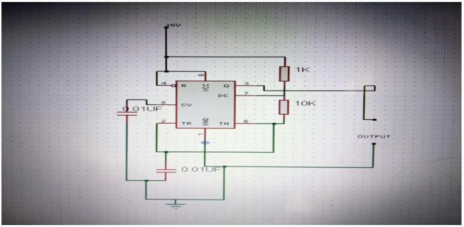
Fig 2. Basic 555 multivibrator
CLK/Osci
llator
Decade
Counter
Decoder
/DAC
O/P
Buffer
ISSN(Online): 2319-8753 ISSN (Print): 2347-6710
I
nternational
J
ournal of
I
nnovative
R
esearch in
S
cience,
E
ngineering and
T
echnology
(A High Impact Factor, Monthly, Peer Reviewed Journal)
Visit: www.ijirset.com
Vol. 8, Issue 10, October 2019
555 timers is used as a free astable multivibrator by wiring it in the basic configuration of fig b with trigger pin shorted to pin 6 threshold terminal and timing resistor R10 wired between pin 6 and discharge pin 7. When power is first applied to this circuit C3 starts to discharge exponentially via R9 to R10 until eventually the C3 voltage rises to 2/3 VCE at which point discharge pin 7 switches low and starts to discharge C3 via r10 until eventually the C3voltage falls to 1/3 Vcc and trigger pin 2 is activated thus initiating a whole new timing sequence, which repeats ad infinitum. The operating frequency is made variable by adding R2 with a series wired variable resistor as shown in fig b.
The frequency can be varied from about 650 Hz to 7.2 kHz through VR1. Selecting alternative values of C3 can also increase the frequency
𝑓 = 0.72
(𝐶3𝑅2 + 𝑉𝑅1)
Stepper motors
A stepper motor is an electromechanical device which converts electrical pulses into discrete mechanical movements. The sequence of the applied pulses is directly related to the direction of motor shafts rotation. The speed of the motor shafts rotation is directly related to the frequency of the input pulses and the length of rotation is directly related to the number of input pulses applied ( Bhale et al, 2016).
4017 decade counter
The decade counter belongs to the family of CMOS logic ICs and it is the building block of this design. It looks like any other 16 pin integrated circuit. They are used in timing systems and as applicable to this design in motor systems.
The pulses from the 555IC pin 3 are used to activate this circuit through pin 14 called “cock in”. Continuous pulsing by the 555IC results in the 4017 turning ON and OFF in sequence, creating a ripple effect. The digital signals from the 4017 counter are fed to the DAC. As the low to high voltage pulses are applied to the “clock in” terminal of the 4017IC, it increments the count thereby forcing the next output into a “high” state.
The waveform is plotted using the nominal voltage supply and 10 switches s0 to s9. Since the generated waveform could be amplified or reduced using external amplifier or divider respectively, the standard voltage used in working out the waveform may not matter.
The voltage VR1 drop across resistor R1, 10k which is kept constant is recorded in table 1
Table 1 Voltage at 4017 counter
Voltage 0.8 1.0 1.5 2.0 2.5 2.5 2.0 1.5 1.0 0.8
Switch S0 S1 S2 S3 S4 S5 S6 S7 S8 S9
Table 1 is the nominal voltage values at the ten switches of the decade counter. This values are used to plot the waveform of the designed system using an oscilloscope.
ISSN(Online): 2319-8753 ISSN (Print): 2347-6710
I
nternational
J
ournal of
I
nnovative
R
esearch in
S
cience,
E
ngineering and
T
echnology
(A High Impact Factor, Monthly, Peer Reviewed Journal)
Visit: www.ijirset.com
Vol. 8, Issue 10, October 2019
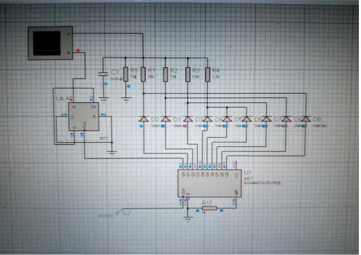
Fig 3. Schematic diagram of the function generator
ISSN(Online): 2319-8753 ISSN (Print): 2347-6710
I
nternational
J
ournal of
I
nnovative
R
esearch in
S
cience,
E
ngineering and
T
echnology
(A High Impact Factor, Monthly, Peer Reviewed Journal)
Visit: www.ijirset.com
Vol. 8, Issue 10, October 2019
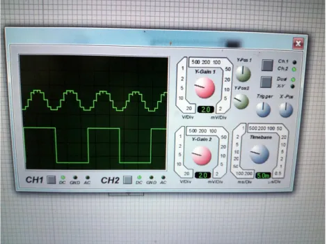
Fig 4. Virtual Wave form simulated by Proteus software
Fig 4 is the waveform of the designed system as was simulated by the proteus software where the designed system was first embarked upon before implementation on a hard ware and tested with a stepper motor.
IV. CONCLUSION
This paper presents a low cost effective way for generation of signal for stepper motor application using a combination of decade counter and timer circuitry. The function generator was tested with stepper motor to confirm its operation function ability.
REFERENCES
[1] Bhale R.C, Sharma G.P, Lanjewar M, S and Thakre H. “Comparative Analysis of Stepper Motor Drivers” International Journal on Recent and
Innovation Trends in Computing and Communication, vol.4, Issue 5, pp213-218, 2016
[2] Bobade D.B and Bobade R.D. “Arduino Based Function Generator” 2nd National Conference Recent Innovations in Science and Engineering
(NC-RISE 17), vol 5, Issue 9, pp86-88, 2017
ISSN(Online): 2319-8753 ISSN (Print): 2347-6710
I
nternational
J
ournal of
I
nnovative
R
esearch in
S
cience,
E
ngineering and
T
echnology
(A High Impact Factor, Monthly, Peer Reviewed Journal)
Visit: www.ijirset.com
Vol. 8, Issue 10, October 2019
[4] Gupta Nandkishor, Prashant Sediwal and Prabhat Pandey “Low-Cost Arbitrary Waveform Generator for Educational Environment Using
ARM7”, Int. Journal of Engineering Research and Applications, vol 3,Issue 6, pp951-956, 2013
[5] Zhong R. Y., G. Q. Huang, Q. Dai and T. Zhang, “Mining SOTs and dispatching rules from RFID-enabled real-time shopfloor production
data”, Journal of Intelligent Manufacturing, vol 25, pp825-843, 2014
[6] Min Wang & Carlos E. Saavedra “Very low frequency tunable signal generator for neural and cardiac cell stimulation”, International Journal of
Electronics, vol 98, Issue 9,pp1215-1227, 2011
[7] Veeravalli, A., Sanchez-Sinencio, E., and Silva-Martinez, J. „A CMOS Transconductance Amplifier Architecture with Wide Tuning Range for
Very Low Frequency Applications‟, IEEE Journal of Solid-state Circuits, vol 37, pp776–781, 2002.
[8] Nandkishor Gupta, Prashant Sediwal, Prabhat Pandey “Cost Arbitrary Waveform Generator for Educational Environment Using ARM7” Int.
Journal of Engineering Research and Applications Vol. 3, Issue 6, pp.951-956, 2013
[9] Jufang Hu, “Design and Implementation of a High-frequency Signal Generator using the DDS Mixing Principle”, International Journal of