Communication and Self-Location of Wireless
Sensor Network or Nodes Using Wireless System:
Implementation of VANET
Monica R. Dhawale#1, Dr. S.A.Ladhake*2
#
ComputerEngineering ,Electronics & Telecommunication, S.G.B.A.University Amravati,
*
S.G.B.A.University,Amravati,Maharashtra ,India
Abstract— The main objective of Global positioning system (GPS) is to determine our position on earth in three dimensions: east-west, north- south, and vertical in terms of longitude, latitude and altitude. Networks are being used in various areas and the demand of users has motivated the emergence of the Vehicular Ad Hoc Network (VANET). VANET is a dynamic network without fixed infrastructure and can be deployed as multi-hop packet networks. It is a wireless network and has dynamic topology due to its node mobility. VANET has its own routing protocols which can compromise with frequent route exchange, dynamic topology, bandwidth constraint and multihop routing. Ad hoc On Demand Distance Vector (AODV) is one of the routing protocols in VANET. Packets are routed between the nodes using the location information of the nodes. Sensing node is the base station and it will continuously sense the exact location of the vehicles. The 4G VANET network is designed using Worldwide Interoperability for Microwave Access (WiMAX). Simulations are performed using NS2 by varying the mobility of nodes as well as the number of nodes. The results achieved from the test have been evaluated using the throughput, jitter, delay, packet delivery ratio (PDR) and packet loss ratio (PLR).The tests illustrates that the increase of throughput and PDR performance was parallel with the increase of packet size.
Keywords: Vehicular Ad hoc Network (VANET), safety and non safety application, attackers, attacks, Security, classes.
I.INTRODUCTION
In recent years, ultra-wide-band (UWB) technologies havedrawn great interest in the wireless community [1]. The development of UWB has ushered in a new era in short-range wireless communications. Among various potential applications, one of the most promising is in wireless sensor networks (WSNs)[2]-[4], which requires both robust communications and high-precision ranging capabilities. There have been numerous research results in the literature to indicate that UWB is one of the enabling technologies for sensor network applications [5]. UWB systems have potentially low complexity and low cost, with noise-like signal properties that create little interference to other systems, are resistant to severe multipath and jamming, and have very good time domain resolution allowing for precise location and tracking. Various ultra-wide-band wireless sensor network applications include locating and imaging of objects and environments [5], perimeter intrusion detection[6], video surveillance[7],
in-vehicle sensing[8], outdoor sports monitoring [8], monitoring of highways, bridges, and other civil infrastructure [9], and so on. The feasibility of UWB technology for wireless sensor network applications including UWB chip and radio module design and precision locating system designs. Recognizing these interesting applications, a number of UWB-based sensor network concepts have been developed both in the industrial and the government/military domain. In this project, we will provide an implementation of VANET as the greatest application of Self-location method. Vehicular ad-hoc networks (VANETs) are networks in which each node is a vehicle. Such systems aim to provide communications between individual vehicles and between vehicles and nearby fixed equipment, or roadside units. The goal of VANETs, and more broadly vehicular networks, is to improve traffic safety by providing timely information to drivers and concerned authorities.
WiMAX
WiMAX (Worldwide Interoperability for Microwave Access) is a wireless communications standard designed to provide 30 to 40 megabit-per-second data rates. WiMAX refers to interoperable implementations of the IEEE 802.16 family of wireless-networks standards ratified by the WiMAX Forum. Mobile WiMAX is a broadband wireless solution that enables convergence of mobile and fixed broadband networks through a common wide area broadband radio access technology and flexible network architecture. The Mobile WiMAX System Profile enables mobile systems to be configured based on a common base feature set thus ensuring baseline functionality for terminals and base stations that are fully interoperable. Some of the salient features supported by Mobile WiMAX are:
1.High Data Rates
2.Quality of Service (QoS) 3.Scalability
4.Security 5.Mobility.
Usually these transceivers should be small and inexpensive so that they can be produced and deployed in large numbers. The main goal of the network is to communicate sensor data with given reliability and delay constraints. The transmission of data from the source to the destination may occur in several hops, where some nodes in the network operate as relays for the transmission the information. Such relaying makes it easier to transmit information across a large network, and transmission over various paths also increases the robustness with respect to an individual node failure. Apart from data communication, geolocation is another key aspect for many wireless sensor network applications. Normally, a number of nodes communicate their sensing (measurement) results to each other and/or a control center. In many cases, the control center or the receiving nodes need to know the exact location of the transmitter. Location information is also important because monitoring and control systems often perform data analysis based on both spatial and temporal correlation from closely spaced sensors. For example, when a fire sensor detects the fire, the control center not only wants to know that there is a fire but also wants to know at which location. WiMax is a more mature technology and has been widely adopted in various applications. WiMax technology has been applied only to perform some particular functions in wireless sensor networks. In many cases, it is used to collect sensor data for transmission over longer distance with fixed power supply. In some industrial and hospital wireless network systems, WiMax have also be used to monitor and locate facilities with an accuracy of several meters. Many research found that Self location method of wireless sensor network is mostly useful in vehicle tracking. The goal of VANET research is to develop a vehicular communication system to enable quick and cost-efficient distribution of data for the benefit of passengers’ safety and comfort.Vehicular Ad-hoc Network(VANET) communication has recently become an increasingly popular research topic in the area of wireless networking as well as the automotive industries.
III.ANALYSIS OF PROBLEM
Sensor network bringing the problem of self-localization for an ad-hoc deployment of wireless sensor nodes. Sensor localization, i.e., obtaining esti-mates of each sensor’s position as well as accurately representing the uncertainty of that estimate, is a critical step for effective application of large sensor networks to almost all subsequent task. The development of VANETs has received much attention from the automotive industry and government agencies, including the US Departmentof Transportation (DOT) which has launched the IntelliDrive initiative (US-DOT 2010). The USDOT reports that in 2008, 37,000 people died in traffic accidents in the US. The agency sees the promise of IntelliDrive, and VANETs in general, to be able to significantly reduce that number.
In order to provide applications that can fulfill this vision, approaches must be thoroughly evaluated. As this is prohibitively expensive for most academic researchers, the majority of evaluation studies have been performed via simulation.
VANET simulations have typically been segregated into traffic simulations and network simulations. Traffic simulators, such as CORSIM (Halati, Lieu, and Walker 1997), SUMO (Krajzewicz,Bonert, and Wagner 2006), VISSIM (PTV America 2010), and VanetMobiSim (Fiore et al. 2006) havebeen used to generate realistic mobility traces of vehicle traffic.
As concerned to this paper, to solve this problem I tried to get some information from internet. Finally I decided the flow of my research work. It is as follow.
1.Firstly I tried to get information on VANET. 2.Studied problems occurred in VANET system. 3.Tried to understand the concept of communication in between the vehicles.
4.Then I moved towards the traffic generator. 5.Studied the concept of GPS in detail.
6.Studied the concept of wireless sensor network.
IV .PROPOSED WORK AND OBJECTIVES
In this paper, we are proposed implementation of Vehicular Ad-Hoc Network (VANET) as an application of self location method using WSN. To implement this, I followed the steps given below.
1.Create the wireless network with number of vehicles. 2.Apply all the wireless network parameters to this
network.
3.Use suitable antenna to transmit and receive the signals. 4.Decide packet size and packet interval time properly. 5.Apply IP address to all the nodes in the network.
6.Apply sensor to the base station to track the exact location of the vehicle.
7.Apply traffic generator to all the transmitting vehicles and null to receiving vehicles.
8.Study the generated trace file and calculate the parameters value from trace file.
A. Design of VANET network using WiMAX
In the Network simulator the VANET network is designed by setting various parameters like channel type, radio-propagation model, network interface type, MAC type, interface queue type, antenna model.
B. Implementation of GPS system in our VANET Network
GPS enabled mobiles are considered as nodes of our VANET network and number of vehicular nodes are set to construct ad-hoc network. The tracking mechanism developed provides knowledge of geographic location of nodes.
i.Define simulator
#create the simulator set ns [new Simulator]
ii.Define topology
In this step, define the area (in terms of size) under which the simulation occurs. We must define it keeping in view the possible locations of our nodes.
#create the topography set topo [new Topography]
$topo load_flatgrid $opt(x_direction) $opt(y_direction)
iii.Define the General Operations Director (“GOD”)
used to store global information about the state of the environment, network or nodes/ We need to define the GOD to manage the details of operations we supply such as the movement patterns in our simulations.
# Create God
create-god <no. of nodes + no. of base_station>;
iv.Define access point/base station and configure the AP/BS
To create and configure a base station or an access point in NS-2, it is preferable to define the options we want to configure the AP/BS with.
v.Define wireless node, configure it and attach to AP/BS
Creating and configuring a wireless node is very similar to what we needed to do with the AP.
vi.Define traffic generator agent and attach it to the source and destination node
To define the traffic flow, we need to designate the nodes as source or destination and decide the type of application/traffic.
1.The first step is to define the source agent.
2.Then designate which node assumes the agent we defined. 3.Define the traffic/application type and attach it to source agent.
4.It should be noted that each traffic type comes with default values of traffic parameters like rate and packet size which can be easily overridden with the set command. 5.Now define the destination agent and attach it.
6.It must be noted that source and destination agents form a pair, and though many options are available for a type of agent, not all of them all compatible with each other. 7.Finally, we can connect the agents.
It is necessary to tell the simulator when to start and stop the traffic flow. To do so we schedule events that controls the agents’ activities.
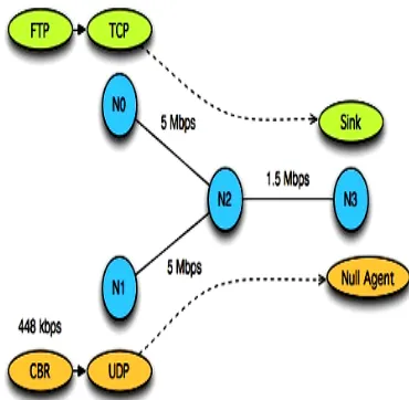
Figure 1 : Connection between the sending node and receiving node
vii.Run simulator
To order the simulator to execute, we simply need to provide the following statement in the script.It is necessary to clear variables and close files after the simulation ends. It is customary to create a procedure for that.
$ ns <file_name>
viii.Introducing mobility
The mobile nodes actually move. Fortunately, NS-2 makes
it really simple to move mobile nodes. We just have to add one line in the script after creating the node. If the node is moving away, it exits the coverage area of the AP as soon as the SNR falls below a specified level. In fact it triggers a handoff, but in our case there is no other AP that the node can be handed over to and hence the connection is lost. $ns at <Starting_instant> "$<name_of_node> setdest <x position> <y position> <z position>"
ix.Tracing Objects
NS simulation can produce visualization trace as well as ASCII file corresponding to the events that are registered at the network. While tracing ns inserts four objects: EnqT, DeqT, RecvT & DrpT. EnqT registers information regarding the arrival of packet and is queued at the input queue of the link. When overflow of a packet occurs, then the information of the dropped packet is registered in DrpT.DeqT holds the information about the packet that is dequeued instantly.RecvT hold the information about the packet that has been received instantly.
Figure 2 : Format of Trace File
Structure of Trace files
1.The first field is event. It gives you four possible symbols '+' '-' ‘r’’d’. These four symbols correspond respectively to enqueued, dequeued, received and dropped respectively. 2.The second field gives the time at which the event occurs. 3.The third field gives you the input node of the link at which the event occurs.
4.The fourth field gives you the output node at which the event occurs.
5.The fifth field shows the information about the packet type.i.e whether the packet is UDP or TCP.
6.The sixth field gives the packet size.
7.The seventh field gives information about some flags. 8.The eight field is the flow id(fid) for IPv6 that a user can set for each flow in a tcl script. It is also used for specifying the color of flow in NAM display.
9.The ninth field is the source address. 10.The tenth field is the destination address.
11.The eleventh field is the network layer protocol's packet sequence number
12.The last field shows the unique id of pack.
V.RESULT AND DISCUSSION
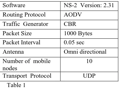
Software NS-2 Version: 2.31 Routing Protocol AODV
Traffic Generator CBR Packet Size 1000 Bytes Packet Interval 0.05 sec
Antenna Omni directional Number of mobile
nodes
10
Transport Protocol UDP Table 1
A.Comparison of AODV Protocol in terms of Sent bytes at current node
A send event for a specified node triggers the call to the node’s procedure responsible for preparing a message. Figure shows the bytes sent at the current node i.e. node 0 with Send Event Time(Simulation Time) in sec.
Fig. 3 Variation of sent bytes with send event time(sec.)
B.Comparison of AODV Protocol in terms of Received bytes at current node
It also schedules the corresponding receive event(s) for the message receiver(s) that are determined by the simulator according to the wireless network model. The receive event is associated with a node (group of nodes) to which the message is transmitted (broadcasted). Its action is to call the appropriate handler in each of the receiving nodes. Figure shows the fraction of bytes are received at the starting position and then it is slowly increases with Receive Event Time(Simulation Time) in Sec.
Fig. 4 Variation of received bytes with Receive event time(sec.)
C.Comparison of AODV Protocol in terms of Throughput of sending bits
Network throughput is the rate of successful message delivery over a communication channel. Throughput is the number of messages successfully delivered per unit time. Figure shows the Throughput in AODV varying the simulation time.
Fig. 5 Variation of Throughput of sending bits with simulation time
D.Comparison of AODV Protocol in terms of Throughput of Receiving bits
In this figure, Throughput is the number of bits receiving per unit time.Figure shows the Throughput in AODV varying the simulation time.
Fig. 6. Variation of Throughput of Receiving bits with simulation time
VI. APPLICATION
Along with the rapid advances in electronics and wireless communications are the broad applications of Wireless Sensor Networks (WSN). WSN is formed by densely and usually randomly deploying large number of sensor nodes either inside or very close to the phenomenon that is being monitored. Thus, the applications can be both military and civilian, such as environment monitor, wild animals track, homeland security, etc.
Sensor networks have many applications from the field of medical to battle field and from the homeland security to earthquake monitoring.
This section describes some of the most prevalent applications for wireless sensor networks.
1.Emergencies (E91 I, El 12)
The first widespread application of Global Positioning System (GPS) in cell-phones is E911 (Enhanced 911) location. When someone dials an emergency (911) call in the United States, the cell-phone must deliver the location of the phone. The US Federal Communications Commission has mandated this’. In Europe a similar mandate, “El12”, is being considered. The location of the caller will appear on a map in front of the 911 operator and this information, even the whole map, will be passed on to the emergency teams that travel to the site.
2.Safety
classified under safety related applications where the main emphasis is on timely dissemintation of safety critical alerts to nearby vehicles.
3.Internet Connectivity
Accessing emails, web browsing, audio and video streaming are some of the connectivity related applications where the emphasis is on the availability of high bandwidth stable internet connectivity While Info stations and 3G/4G primarily provide the vehicle to infrastructure(gateway) communication (V2I) in the context of vehicular communication,VANETs assumes a more generic framework that includes both the vehicle to vehicle communication (V2V) and limited V2I communication with higher emphasis on the V2V communication. It is important to understand that the V2I communication model in VANETs is not well defined and most of the current proposals assume the presence of limited or intermittent internet connectivity.
The main factors that would influence the adoption of VANET architecture for future vehicular applications would be –
1) Low latency requirements for safety applications.
2) Extensive growth of interactive and multimedia applications.
3) Increasing concerns about privacy and security.
4.Health Applications
Vehicular networks can become a convenient data mule for any type of information. Vehicles as a transport infrastructure for patient health data, useful whenever patients leave primary care centers and therefore an AP coverage. Each patient is equipped with a set of sensors, a processing gateway and an on-body terminal. Vehicles periodically send advertisement messages that can be received by the on-body terminal. These messages contain the vehicle’s position and IP information. When the on-body terminal receives this information, it decides to initiate or not a connection depending on the availability of data. We can see how the amount of data that is transferred increases when deploying more cars.
ADVANTAGES AND LIMITATIONS
i. Advantages
1.Vanet are Frequent and very fast. 2.Mobility is High.
3.Node Density is High and Frequently Variable 4.Bandwidth across Network is very High. 5.Range Of communication is over a wide area. 6.Reliability is High.
7.Positioning of vehicles is accurate using GPS systems. 8.Road Safety will be increased in case of emergencies quick medical services will be made available.
ii. Limitations
1.Cost of Production of such Systems will be very expensive.
2.Providing Security and privacy to each vehicle will be a big challenge is real time.
3.Implementing all this is also a big challenge and will long time span.
VII.CONCLUSION
The research shows that the exact location of vehicles in large coverage area in present or past by using global positioning system (GPS) in 4G communication system can be find out. In this paper, we assessed the performance of AODV routing protocol for different packet interval in homogeneous VANET Network. The results shows that AODV routing protocol in VANET is good. In the simulation, the size of the packets transmit has a large impact on throughput and PDR in wireless environment. The result shows as the size of packet size increase, the throughput and PDR also will increase except for certain circumstances when the size of packets achieve certain limits as the large packet size keeps the transport layer channel busy and it affected the value.
VIII. FUTURE WORK
The future works could involve the comparison of the AODV routing protocol with other routing protocols like OLSR or ZRP in heterogeneous VANET. Heterogeneous VANET is composition of many ad-hoc networks which will require a more efficient routing protocol.
Studies of the performance of the AODV routing protocol can lead to the development of an optimal enhanced AODV protocol which can maximize routing performance, particularly in heterogeneous networks. The new AODV will hopefully improve the performance of routing in heterogeneous MANET. Further a technique can also be devised to know about the contents of a particular packet.
REFERENCES
[1] M. G. diBenedetto, T. Kaiser,A. F. Molisch, I. Oppermann, C. Politano, and D. Porcino, Eds., UWB Communications Systems: A Comprehensive Overview. Darmstadt, Germany: EURASIP, 2005. [2] P. Martigne, BUWB for low data rate applications: Technology
overview and regulatory aspects,[ in Proc. IEEE Int. Symp. Circuits Syst. (ISCAS), 2006, pp. 2425–2428.
[3] K. D. Colling and P. Ciorciari, BUltra wideband communications for sensor networks,[ in Proc. IEEE Military Commun. Conf. (MILCOM), 2005, pp. 1–7.
[4] S. Gezici, Z. Tian, G. B. Giannakis, H. Kobayashi, A. F. Molisch, H. V. Poor, and Z. Sahinoglu, BLocalization via ultra-wideband radios: A look at positioning aspects for future sensor networks,[ IEEE Signal Process. Mag., vol. 22, pp. 70–84, 2005
[5] R. S. Thoma, O. Hirsch, J. Sachs, and R. Zetik, BUWB sensor networks for position location and imaging of objects and environments,[ in Proc. 2nd Eur. Conf. Antennas Propag. (EuCAP), 2007, pp. 1–9.
[6] X. Huang, E. Dutkiewicz, R. Gandia, and D. Lowe, BUltra-wideband technology for video surveillance sensor networks,[ in Proc. IEEE Int. Conf. Ind. Inf., 2006, pp. 1012–1017.
[7] J. Li and T. Talty, BChannel characterization for ultra-wideband intra-vehicle sensor networks,[ in Proc. Military Commun. Conf. (MILCOM), 2006, pp. 1–5.
[8] I. Oppenmann, L. Stoica, A. Rabbachin, Z. Shekby, and J. Haapola, BUWB wireless sensor networks: UWENVA practical example,[ IEEE Commun. Mag., pp. S27–S32, 2004.
[9] V. Mehta and M. EI Zarki, BAn Ultra Wide Band (UWB) based sensor network for civil infrastructure health monitoring,[ in Proc. 1st Eur. Workshop Wireless Sensor Netw. (EWSN), Berlin, Germany, Jan. 19–21, 2004.
[10] Arbabi, H., and Weigle, M. 2010. Highway Mobility and Vehicular Ad-Hoc Networks in NS-3, In Proceedings of the 2010 Winter Simulation Conference.
[11] Treiber, M., and D. Helbing. 2002. Realistische Mikrosimulation von Straßenverkehr miteinem einfachen Modell , In Proceedings of the 16th Symposium Simulationstechnik (ASIM 2002), 514—520.
<http://www.grinninglizard.com/tinyxml/> Visited October 24, 2011 [13] Kun-chan Lan and Chien-Ming Chou ,“Realistic Mobility Models for
VANET Simulations”.
[14] SUN Xi , LI Xia-miao, “Study of the Feasibility of VANET and its Routing Protocols”.
[15] Brijesh Kadri Mohandas, Ramiro Liscano, “IP Address Configuration in VANET using Centralized DHCP”.
[16] Marfia, G., Pau, G., De Sena, E., Giordano, E., and Gerla, M. 2007. “Evaluating vehicle network strategies for downtown Portland: opportunistic infrastructure and the importance of realistic mobility models”. In Proceedings of the 1st international Mobisys Workshop on Mobile Opportunistic Networking (San Juan, Puerto Rico, June 11 - 11, 2007). MobiOpp ’07. ACM, New York, NY, 47-51.
[17] Marfia, G.; Pau, G.; Giordano, E.; De Sena, E.; Geria, M., “VANET: On Mobility Scenarios and Urban Infrastructure. A Case Study,” in 2007 Mobile Networking for Vehicular Environments, vol., no., pp.31-36, 11- 11 May 2007.
[18] C.E. Perkins, E.M. Royer, “Ad-Hoc On Demand Distance Vector Routing,” in Proceedings of the 2nd IEEE Workshop on Mobile Computing Systems and Applications (WMCSA), pp. 90-100, February, 1999, New Orleans, Alabama, USA.
[19] CORSIM (2008). Microscopic Traffic Simulation Model. Retrieved March 19, 2008, from http://mctrans. ce.ufl.edu/featured/tsis/version5/corsim50. Htm.
[20] Katz, J. H. (1963). Simulation of a Traffic Network. Communications of the ACM, 6(8), 480-486.