R E S E A R C H
Open Access
Resource allocation in relay enhanced
LTE-Advanced networks
Thiago Martins de Moraes
*, Muhammad Danish Nisar, Arturo Antonio Gonzalez and Eiko Seidel
Abstract
Relay deployment in future mobile networks is a vital measure to enhance the coverage region of regular base stations, to overcome shadowing dips, and to bring improvements in the cell-edge performance. In this regard, resource allocation in a relay-enhanced scenario is a key design task, and has become a very interesting research topic over the past few years. In this article, we study two main resource allocation aspects of a relay-enhanced scenario. First, we concentrate on the problem of multiplexing the relay backhaul link and the direct link at the base station scheduler for in-band as well as out-band relay operations. We propose three distinct resource partitioning strategies, and evaluate their performance via long-term evolution (LTE) system level simulations in the downlink direction. We observe that even the low implementation effort algorithms bring appreciable improvement for the cell-edge users with or without small loss in performance for the other users, thereby enhancing system fairness. Second, we visit the problem of supporting heterogeneousquality of service(QoS) requirements in a multi-user relay-enhanced network. To this end, we introduce a QoS-aware scheduler which uses packet latency and rate requirements to prioritise the scheduling decisions. Moreover, we also propose a mechanism to support QoS-constrained services to the relayed users, served over two (or more) hops. Employing an LTE system level simulator, for relay-enhanced scenario with a traffic mix having distinct QoS requirements, we demonstrate that the proposed QoS-aware resource allocation strategy significantly increases the fraction of QoS-satisfied users.
Keywords: Relay, Resource allocation, Quality of service (QoS), In-band, Out-band, LTE-Advanced, Carrier aggregation, Radio resource management
1 Introduction
The past few years have brought new possibilities that changed the mobile users’ expectations regarding con-nectivity. New social applications, high-definition multi-media, and other services have made mobile terminals the main connectivity tool for several users, i.e., users want to have the same experience as on a fixed computer. The upcoming standard from3rd Generation Partnership
Program (3GPP) named long-term evolution advanced
(LTE-A) targets the support of such high requirements services.
Relaying is an appealing technology that was introduced in LTE-A to provide seamless connection and high achiev-able data rates to the users located in the cell-edge or in coverage holes [1,2].Relay nodes(RN) are low power evolved NodeB (eNB)which, when deployed in the macro
*Correspondence: moraes@nomor.de
Nomor Research GmbH, Brecherspitzstr. 8, 81541 Munich, Germany
cell, improve the signal quality between theuser equip-ment (UE) and eNB by dividing the radio link into two hops: the so-called backhaul link between the RN and the eNB, which in this context, is referred to as theDonor eNB (DeNB), and the so-called access link between the RN and the UE [3].
Resource allocation among multiple users sharing the whole spectrum bandwidth is one of the key design tasks in LTE systems. The aim here is to optimally assign resources to those users which need them, keeping in view not only their resource requirements, but also their instantaneous channel quality, instantaneous service qual-ity, and the allocation history. Although, the presence of RN (multi-hop transmission) has proved to enhance the LTE system [4-7], it introduces some additional design challenges in the traditional resource allocation task. This article is precisely dedicated to addressing the resource allocation challenges inrelay-enhanced networks (REN), and here we explore the following key issues:
• How to split the radio resources at DeNB for serving the direct and the backhaul link?
• How to ensure thatQuality of Service (QoS) constraints of all users, including those served over multiple hops, are appropriately satisfied?
1.1 Resource partitioning in REN
In presence of an RN, the radio resources at the DeNB are shared between the backhaul link and the direct link. This happens in the context of both in-band and out-band modes of relay operation (as described later). A crucial task here is to decide on how the resources are going to be shared, i.e., how many resources should be assigned for backhaul transmission and how many should be used for the direct link.
The problem of such resource partitioning in an REN was considered as early as 2005 in [8]. However, the type of segregation between the backhaul link and the access link considered in this study is fundamentally different from the current assumptions in the LTE-Advanced stan-dard. Nevertheless, this article established that an optimal resource allocation in such a scenario is an NP-Hard prob-lem and proposed a heuristic algorithm to achieve a sub-optimal resource partitioning in REN for the considered mode of operation.
Wang et al. [9] studied the problem of resource allo-cation in LTE-Advanced systems in presence of carrier aggregation for a combination of advanced and legacy users. The goal was to devise a manner to reap the max-imum benefits in terms of overall system performance without damaging the performance of legacy users. How-ever, this study does not consider the presence of relays.
Later on, the problem was considered in [10] for an orthogonal frequency division multiplexing-based cellu-lar system. This article considered in-band mode of relay operation, and proposed an algorithm to multiplex the macro access and the backhaul link at the DeNB by considering the status of the transmitting queues of the users. In a situation of competing users, the resources (sub-carriers) were proposed to be randomly distributed among the users. Although, the authors showed an increase in the system capacity by using their simple rout-ing strategy and opportunistic resource allocation scheme, they did not fully consider the LTE-A constraints, such as the presence of the so-calledmultimedia broadcast single frequency networks(MBSFN) sub-frames.
The problem of resource allocation in relay-enhanced LTE-A networks was analysed in [11] where the allocation problem is defined as a system performance optimisation problem and the authors show that the optimal through-put is achieve when the backhaul link defines the relay system’s bottleneck. However, no scheduling is considered in that work and the allocation considers that the DeNB is aware of the backhaul and access links spectral efficiency.
Moreover, Saleh et al. [12] propose a resource allocation for type-1 relays. Nevertheless, in that work no partition between the backhaul and the access links are proposed and the authors concentrate on the access link allocation.
Finally, REN with carriers aggregation is studied in [13,14]. In these contributions, Gora et al. compare the performance of in-band relays and out-band relays with carrier aggregation. But their work also does not con-sider resource partition between the direct link and the backhaul link. Moreover, none of the above cited work [8-14] considers QoS support for users while designing the resource allocation schemes.
1.2 QoS provisioning in REN
Resource allocation for satisfaction of heterogeneous QoS requirements in presence/absence of relays has been an active area of research over the past few years. Liu et al. [15] tackle the QoS-aware scheduling in multi-hop wire-less mesh networks by proposing a manner to consider the delay and the rate requirements of all relayed users in the scheduler at each of the scheduling nodes. Neverthe-less, in this study advanced relays for LTE-A deployments and their specific requirements and constraints are not considered.
The support of QoS in LTE-Advanced for mixed traf-fic is studied in [16] which divides the traffic types into two classes: real-time traffic and non-real-time traffic. The flows belonging to the non-real-time traffic are sched-uled based on a proportional fair metric which is scaled by the respective QoS requirements, and a scaled Max C/I approach is used to scheduled the real-time traffic. However, this study also does not consider the resource allocation challenges in an REN.
Finally, Ma et al. [17] focus on the issue of resource allo-cation for LTE-A relays, and propose to do the resource partitioning between the direct and the backhaul links, using a proportional fair-based algorithm. However, no explicit QoS support for the multiplexed users is consid-ered by them.
1.3 Our contribution
In this article, we focus on the problem of resource alloca-tion in relay-enhanced future wireless networks from two perspectives. Resource partitioning between the backhaul and the direct links is the starting point of our work. We propose different strategies [18,19] which target at achiev-ing fairness in REN. Furthermore, we extend the previous studies to support QoS-aware services in LTE-A REN [20]. It is worth mentioning that although the proposed solu-tions are oriented towards relaying in LTE-A, yet they are generic enough, and can easily be applied to other REN deployments with heterogeneous QoS requirements.
consideration. Section 3 details our investigations and proposals on each of the two issues highlighted above. In Section 4, we describe the simulation model, assumptions, and parameters, while in Section 5, the simulation results are presented and discussed. Finally, Section 6 concludes the article.
2 System overview
2.1 Relays in LTE-Advanced
In its release 10, LTE-A has standardised the use of RN for enhancing the coverage and the capacity of macro cells. It was decided by 3GPP that LTE-A would offer support for the so-called Type-1 relays which are non-transparent relays [21]. From the UE perspective, the RN is seen as a regular eNB, and from the eNB perspective the RN is an UE with enhanced capabilities. Hence, the relay is mainly composed of two set of antennas to be used for the backhaul and the access links. Since both physical layers are very similar, sufficient isolation must be provided in order to avoid self-interference on the RNs antennas. Depending on the manner that the isolation is achieved the RN are classified as in-band or out-band relays.
The in-band relays operate with the backhaul link allo-cated at the same carrier as the access link. In this case, the transmission–reception isolation at RN is performed in the time domain (TD) using the MBSFN sub-frames [22]. Thus, the RN receives from DeNB only during the MBSFN sub-frames, and transmits to the relayed users only during the non-MBSFN sub-frames.
On the other hand, for the out-band relays, a distinct carrier is used to separate the backhaul and the access links. This can practically be implemented by exploiting the feature of carrier aggregation. Carrier aggregation in LTE-A expands the total available bandwidth by allow-ing the users to use several carries at the same time thereby increasing the achievable data rates [23]. For out-band relay operation, carrier aggregation appears to offer an interesting option to multiplex the backhaul and the access links: while the direct link is scheduled on all avail-able carriers, the backhaul link is limited to a certain subset of them. Meanwhile, the relay access link must be scheduled on the carriers complementary to the backhaul link set.
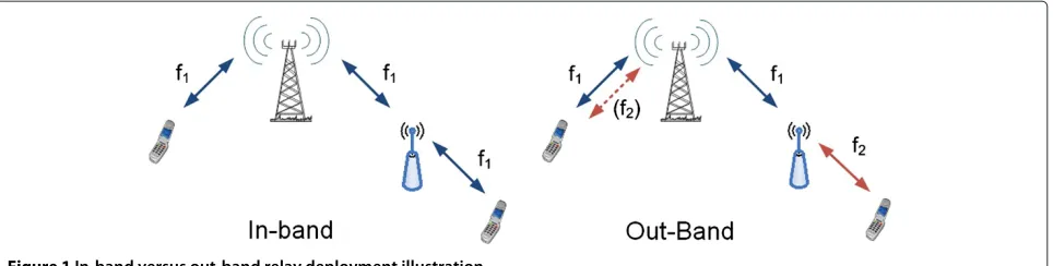
Figure 1 depicts an example type-1 relay deployment. For the in-band relay deployment, on the left side, all the nodes are served using the same frequency band f1, and the segregation is maintained in the TD (data
not shown in the figure). On the other hand, for the out-band relay deployment, on the right side, we notice that while the backhaul link has to be allocated in dif-ferent band than the access link, i.e., f1 andf2,
respec-tively, the direct link can be scheduled in one or both of those bands.
2.2 QoS provisioning in LTE-Advanced
In LTE-Advanced, when a UE has specific QoS require-ments, they are defined using a quality class indicator (QCI) [24]. QCI is a scalar value ranging from one to nine which defines for the traffic flowna set of fix parameters which among others include:
• the delay budget,DProfile(n): the maximum acceptable packet delay;
• the maximum block error rate;
• the service priority index,P(n): a scalar ranging from one to nine; the higher the index, the lower is the service priority;
• some real-time QCIs also specify aGuaranteed bit-rate (GBR), GBR(n), the specification of GBR value for a particular service is left open for the service provider.
In this study, we will mainly focus on the delay bud-getDProfile(n) and the required rate GBR(n) to propose
an efficient QoS-aware resource allocation for relay-enhanced scenarios.
3 Proposed resource allocation strategy 3.1 Explicit resource partitioning at DeNB between
access and backhaul links
Regardless of the in-band or out-band modes of relay operation discussed briefly in Section 2, the DeNB resources are to be shared between the backhaul and the access links. The DeNB is the entity responsible of maintaining the relay UEs (R-UEs) service continu-ity by allocating resources for the backhaul link. When no QoS is specified, the partitioning between backhaul and access link depends, in general, on the desired fair-ness among flows in the system. In this section, we recall the strategies which perform resource partitioning at DeNB for in-band [18] and for out-band [19] relays. The resource partition strategies determine the amount of resources that the DeNB reserves for scheduling the backhaul link of each attached RN. After, the resource partition has taken place the remaining resources are dis-tributed to themacro UEs(M-UEs) using a proportional fair scheduler [18,19]. Furthermore, each RN schedules their subordinated R-UEs using the same proportional fair scheduler.
The so-calledfair resource units(Fair-RU) strategy con-sists in dividing the resources available based on the num-ber of users in each scheduling node as well as the numnum-ber of available resources. For in-band relays, in each MBSFN sub-frame the share of resources given to the backhaul link is defined by
= NR
NR+NM ·
NF
Figure 1In-band versus out-band relay deployment illustration.
whereNRis the number of R-UEs,NMis the number of
M-UEs,Pnumber of MBSFN sub-frames, andNFsub-frame
periodicity. The Fair-RU strategy for out-band RNs with carrier aggregation is defined as
= NR
NR+NM ·
1
σ, (2)
where (σ) is the ratio between number of carriers that can be configured to transport backhaul link data and the total number of carries available at the DeNB. Note that in (2) we assume that all the carriers have the same bandwidth.
In order to allow for dynamic partitioning we also have introduced the Fair-Throughput (Fair-TP) strategy. This algorithm computes the aggregate average throughput on the backhaul and on the direct links, respectively, asφB
and φM. After that, the resources are assigned to the
backhaul link until
φB
NR ≈
φM
NM
. (3)
A third resource partitioning strategy proposed in [19] targeting out-band relays is the so-called extended proportional-fair(Ext-Prop-Fair) strategy. In this strategy, the RN is viewed as a normal UE from the perspective of the scheduler. Nevertheless, the usual Prop-Fair metric is scaled with the number of attached R-UEs, i.e., after the proportional fair metric has been estimated for the back-haul link, the metric is linearly scaled by the number of R-UEs connected to the respective RN.
Figure 2 illustrates the two resource partitioning tech-niques for the case of two in-band RNs and five MBSFN
sub-frames (sub-frames #1, #2, #3, #6, #8). For the Fair-RU (left side), during the MBSFN sub-frames each RN receives a fixed amount of resources depending on the number of connected users. On the right-hand side of Figure 2 a simple allocation example for Fair-TP strategy is shown. Depending on the allocation history the RN can receive more/less resource than the previous sub-frames or be not scheduled as in sub-frame #2.
Figure 3 illustrates the three resource partitioning pro-posals for the out-band relays. The left most part rep-resents the Fair-RU strategy for the case where a single carrier is used to allocate the backhaul link of two dis-tinct relays. The middle figure depicts an example for the Fair-TP strategy for the same system configuration while the right most part shows a sample allocation example for Ext-Prop-Fair.
3.2 QoS-aware resource allocation
3.2.1 Addressing QoS support in relay-enhanced scenarios
In Section 3.1, we have tackled the problem of resource allocation for an advanced relay scenario. However, no consideration has been made towards the provision of QoS constraints which is of importance in future net-works, coping with a mix of traffic types where each type is associated to different QoS requirements. The intro-duction of additional hops in enhanced heterogeneous networks makes the support of such services challenging since a packet must undergo through several schedul-ing processes. For the presented relay-enhanced network, this implies two scheduling processes: scheduling from
Figure 3Out-band case: Representation of the resource allocation strategies during one radio frame for the backhaul link carrier.
DeNB to RN and scheduling from RN to R-UE. There-fore, support of the QoS requirements is only possible if the requirements hold across all the involved radio links. Assuming a radio link consisting ofM number of hops between source and destination, whereM+1 nodes are involved in the transmission of a certain flown, the condi-tions to guarantee the QoS requirements can be expressed as
whereTmdenotes the time it takes data to get from node
m to nodem+ 1. Moreover, BUE is the total data
vol-ume transferred from the source to destination during the intervalMm=1Tm. In particular for the two-hop scenario
of our interest, (4) and (5) become
TDeNB-RN+TRN-UE≤DProfile(n) (6)
BUE
TDeNB-RN+TRN-UE ≥
GBR(n) (7)
whereTDeNB-RNis time interval between the arrival of the
packet at the DeNB until it is has been delivered to the RN,TRN-UEis the time interval between the packet
recep-tion in the RN and its receprecep-tion at the final destinarecep-tion, i.e., the R-UE. BUE is the total data volume transferred
from the DeNB to the R-UE considered during the interval TDeNB-RN+TRN-UE.
We propose to combine the QoS requirements of the R-UE flows multiplexed through the RNs into a sin-gle/multiple “super flow”: All the data flows destined to the R-UEs of an RN and belonging to the same QCI type qare aggregated into a single flow in the DeNB scheduler. Hence, from a DeNB scheduling perspective, independent of the number of R-UEs, there is a single backhaul link flow with QCIqwith an aggregate rate requirement
GBR(B)≥GBR(n). (8)
Furthermore, the delay requirement of the employed QCIqfor the created “super flow” in each scheduling node is defined as
DQoS-B=
DProfile
M , (9)
In general, (9) shows that in order to fulfil the delay requirements of a UE,DProfile, served through a multi-hop
link, we force the schedulers at each node to send pack-etsMtimes faster for every “super flow” as compared to a regular flow. This allows subsequent schedulers to deliver data before the packet arrival deadline. As our scenario consider two hops, the maximum delay for the R-UEs’ flows at each scheduler is
DQoS-B=
DProfile
2 . (10)
3.2.2 Proposed scheduling metric
The QoS scheduling metric is responsible for sorting the UEs according to the data urgency for the upcom-ing schedulupcom-ing round ortransmission time interval(TTI) [25]. In this section, we describe the QoS-aware metric which is based on the observations made on our LTE-A simulators.
The first step towards the definition of our schedul-ing metric is to define the delay coefficientωd(n,t)which
represents the impact of the packet delay on the metric computation: at time instantta packet belonging to the flownhas its delay coefficient given by
The main idea behind (12) is to achieve a balance between the rate and the delay requirements. The first term of the metric aims to guarantee the bit rate: If the average rate of the flow n is smaller than the desired GBR(n), the influence of the rate term increases to the power ofρin an attempt to meet the desired rate. When the average rate matches or surpasses GBR(n), this factor has then no influence on the overall QoS-metric.ωd(n,t)
serves as a mechanism to guarantee that the packet delays do not exceedDProfile(n): WhiledHOL(n,t)is low,ωd(n,t)
has a small influence on (12) and its influence grows exponentially when the packet deadline approaches.
The values chosen forβ andρ depend on the desired system behaviour, i.e., which factor has more influence on the metric. For this study, these variables have empirically been determined and their values were fixed to 4 and 3, respectively.
3.2.3 Two-stage scheduler
The proposed QoS scheduling is performed in two dis-tinct scheduler sub-stages. During the first stage, the so-called TD scheduler sets up a list of candidates that can be scheduled in next TTI. To this end, the TD sched-uler computes the QoS metric of all UEs using (12) and creates the list by sorting them in metric crescent order. To keep the complexity of the scheduling process low, the list is reduced. In other words, after the can-didate list is created, only the top users are maintained whereas the rest of UEs are dropped and not considered in this TTI.
The shortened list is then forwarded to the frequency domainscheduler where the frequency chunks are allo-cated to the UEs: in this process, all the frequency resource units are visited one after the other and for each UE in the TD list, the QoS metric is computed. A resource unit is allocated to the user with the highest QoS met-ric given by (12). After each resource unit is allocated, the average throughput of the chosen UE is updated and the next resource unit is visited. The scheduling process is repeated for the other resource units until all resources have been allocated or no data are left in the transmitting buffers.
4 Simulation setup
The performance evaluation of the proposed strategies is conducted using system-level simulations with multiple UEs. The deployment model studied in this study com-plies with the 3GPP Case-1 for urban macro cells with an inter-site distance of 500 m [21]. In addition, we consider the deployment of two outdoor RNs within the macro cell. The DeNB is located in the left corner of a hexagon-shaped cell and the RNs located along the opposite side at the positions which are based on [26]. The hexagonal shape thus resembles one of the three sectors served by
the DeNB, which corresponds to the reduced single-cell layout specified in [27].
Within the macro cell, a so-called “hot-spot” scenario is assumed: 25 UEs are placed in total such that a pair of 2 UEs, the R-UEs, always ends up in the coverage region of each RN, and the remaining 21 UEs, the (M-UEs), in the coverage region of the DeNB. The coverage region of each node is defined by strongest received ref-erence signal received power (RSRP). Figure 4 depicts the signal-to-interference-plus-noise ratio (SINR) for the used deployment based on the RSRP-defined coverage areas. In addition, all UEs are periodically relocated ran-domly within their respective coverage regions. Hence, no explicit motion model must be considered for now. Finally, we want to note that the same sequence of UE positions is replayed when simulating the macro cell with-out any RN, such that the performance can directly be compared.
4.1 Macro cell configuration
The macro cell is configured according to the parameters specified in the Appendix A of [21]. Here, we recall the most important parameters:
• Duplexing: FDD
• Carrier frequency: 2 GHz
• TTI duration: 1 ms
• Speed: 3 km/h
• Penetration loss: 20 dB
• Path loss: Only NLOS term used
• 3-D antenna pattern with 15 degree electrical downtilt
• DeNB antenna height: 32 m
• UE antenna height: 1.5 m
• Minimum distance between DeNB and UE: 35 m
• DeNB Tx power: 43 dBm
For the simulations involving in-band relays, a band-width of 10+10 MHz is configured while for the out-band relays 2 carries of 5+5 MHz are used. This definition of the bandwidth allows us for direct and fair comparison between the results.
Although, we consider the presence of fast fading in our channel model, the use of log-normal shadowing is skipped in our simulations for simplicity. The interference from all neighbouring cells at non-negligible distance to the macro cell is also considered in our channel model: all the surrounding cells are configured as the studied macro cell. Moreover, in each TTI those eNBs transmit at full power across the whole bandwidth using full buffer traf-fic pattern. The interested reader can refer to [28] for a detailed description of the utilised channel model.
4.2 Relay configuration
As mentioned above, the macro cell is enhanced by two outdoor relays which configurations parameters can be found in Tables A2.1.1.2-2, A2.1.1.2-3, and A2.1.1.4-3 pre-sented in [21].
• Carrier frequency, duplexing, TTI duration, speed, and penetration loss: same as for macro cell
• Path loss: Only NLOS term (for relay to UE) used
• 2-D omni-directional antenna pattern with 5 dBi gain, 2Tx and 2Rx antenna ports
• RN antenna height: 5 m
• UE antenna height: same as for macro cell
• Minimum distance between RN and UE: 10 m
• RN Tx power: 30 dBm
The access link has a bandwidth of 10 and 5 MHz for in-band and out-in-band relay cases, respectively. Note that for the DeNB-RN link, we assume a gain of 5 dB to account for the assumption that a relay has better reception condi-tions than a regular UE [21].
It is worth mentioning that for the QoS-aware simula-tions we consider only in-band relay.
4.3 Traffic model
While simulating the partition strategies, described in Section 3.1, no QoS requirements are considered. Hence, a full buffer traffic model is used for all the users. However, in our QoS-aware evaluation we employ two different traffic types with their distinct QoS requirements:
• Voice over IP (VoIP) traffic is emulated using a constant bit-rate (CBR) traffic generator working at 128 kbps. The QCI for this type of traffic is defined as QCI-1 [24]: The packets are allowed to have a maximum end-to-end delay of 100 ms, and the service priority is defined as 2.
• Video streaming services. In our evaluations we configure a CBR of 256 kbps due to the limitations of the mobile devices, such as processing capabilities. The QCI for this type of traffic is defined as QCI-4 [24]: The maximum packet end-to-end delay is 300 ms, and the service priority is 5.
The desired CBR is created by our traffic generator using a fixed packet size of 256 bytes at appropriate time intervals: 8 ms for video and 16 ms for VoIP traffic.
5 Simulation results
5.1 Explicit resource partitioning at DeNB
In this section, we present a comparison of the pro-posed resource partitioning strategies by comparing the throughputcumulative distribution function(CDF) of all users from the DeNB scheduler perspective. The DeNB-only scenario will be used as reference: all 25 UEs are attached to the DeNB. Notice that the reference scenario for the in-band and out-band cases are not the same because of the different bandwidth settings, as described in Section 4.1. Although, no relays are present in the refer-ence scenario we will still name the cell-edge users located in the future RN coverage as R-UEs to emphasise the fact that these UEs still occupy the same positions as in the relay simulations.
We start presenting the throughput CDF of all users (M-UEs and R-UEs) combined for the reference DeNB-only scenario and the DeNB+2RN scenario with different resource partitioning strategies for in-band (Figure 5) and out-band relays (Figure 6). We observe that for the given deployment scenario with two RNs, all the proposed resource allocation strategies show appreciable gain over
Figure 6Throughput CDF for all UEs: DeNB-only versus out-band relaying strategies (Fair-RU, Fair-TP, Ext-Prop-Fair).
the reference scenario. Nevertheless, for the out-band sce-nario the Ext-Prop-Fair seems to be the preferred solution here due to its unified best performance in the low and medium range and the low implementation effort. On the other hand, we cannot draw a conclusion for the in-band case at this point of our analysis.
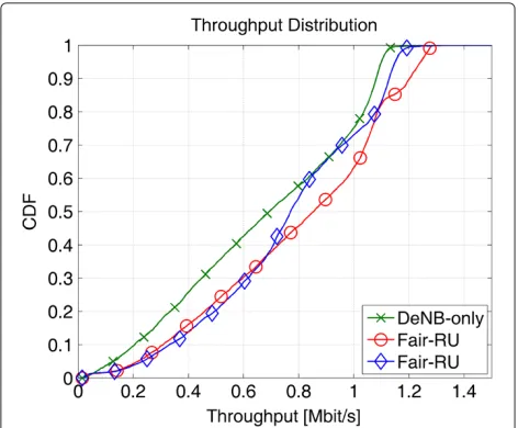
Figure 7 shows that among all in-band strategies the Fair-RU achieves the highest throughput for the R-UEs due to the larger resource consumption of the backhaul link. Correspondingly, the throughput of the M-UEs is lowest with Fair-RU, as can be seen in Figure 8. While the resource unit consumption is fair for this case, the good
Figure 7Throughput CDF for backhaul link (R-UEs): DeNB-only versus in-band relaying strategies (Fair-RU, Fair-TP).
Figure 8Throughput CDF for direct link (M-UEs): DeNB-only versus in-band relaying strategies (Fair-RU, Fair-TP).
channel quality on the backhaul link results in high aver-age throughput for the backhaul link as compared to the direct link, i.e., this strategy overcompensates the back-haul link. Since the Fair-RU strategy by definition include the throughput history in the decision metric, overall throughput fairness is well achieved. Thus, the latter strat-egy seems preferable in this scenario as it improves the cell-edge performance with minimal impact on the M-UEs’ performance.
Figures 9 and 10 depict the same tendency for the out-band relay scenario for the above strategies. Moreover, we can notice that the Ext-Prop-Fair clearly outperforms
Figure 10Throughput CDF for direct link (M-UEs): DeNB-only versus out-band relaying strategies (Fair-RU, Fair-TP, Ext-Prop-Fair).
Fair-TP for the group of R-UEs, while achieving practically the same performance for the group of M-UEs. Hence, it comes out as the preferred choice in the out-band scenario due to better resource utilisation.
5.2 Implicit resource partitioning and QoS provisioning
In the previous section, we analysed the behaviour of the system under different explicitly resource partition-ing strategies. However, as mentioned in Section 3, those strategies are not appropriate when QoS-constrained ser-vices are considered. In this section, we analyse the per-formance of a system employing the QoS-aware resource
Figure 11DeNB+2RN scenario with proposed QoS-aware resource allocation: throughput CDF comparisons for different UE groups (M-UEs and R-UEs) and traffic types (VoIP and video).
Figure 12DeNB+2RN scenario with proposed QoS-aware resource allocation: delay CDF comparisons for different UE groups (M-UEs and R-UEs) and traffic types (VoIP and Video).
allocation strategies proposed earlier. As in the previous analysis, the underlying performance metric is the CDF of the per user throughput measured at the UEs’ layer-2. In this case, we additionally consider the CDF of end-to-end packet delays.
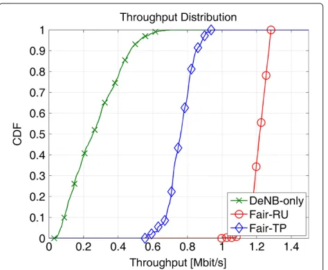
Figure 11 depicts the performance of the proposed QoS-aware resource allocation strategy for different traffic type models (VoIP and video streaming) belonging to different user groups (R-UEs and M-UEs) in a scenario where two RNs are deployed to enhance the user experience inside the macro cell. We observe that the proposed strategy
Figure 14DeNB+2RN scenario with conventional resource allocation (Fair-RU resource partitioning plus proportional fair scheduler): delay CDF comparisons for different UE groups (M-UEs and R-UEs) and traffic types (VoIP and video).
is able to fulfil the user rate requirements of both traffic types to a large extent for all groups. The mean and 5 per-centile throughput values for VoIP traffic type are around 130 and 128 kbps for both M-UEs and R-UEs, respectively. For the video UEs, we observe that the R-UEs are also able to meet the QoS requirements, situation that would not be possible without the deployment of the RN [20]. For the latter group, the mean and 5 percentile throughput values are 261 and 260 kbps, respectively. Although for the video M-UEs, we observe a mean and 5 percentile throughput values of 252 and 195 kbps, there is still a portion of those UEs that are not able to achieve the designated GBR.
In Figure 12, we show the CDF of the end-to-end packet delays for proposed scheme in the same scenario. Note that the end-to-end packet delay corresponds to the aggregated packet delay, i.e., a sum of packet delays expe-rienced over both hops for R-UEs. The R-UE group shows an obvious advantage w.r.t. the M-UEs. The obtained VoIP
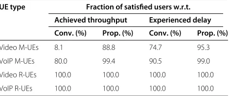
Table 1 Summary of gains from QoS-aware resource allocation
UE type Fraction of satisfied users w.r.t.
Achieved throughput Experienced delay
Conv. (%) Prop. (%) Conv. (%) Prop. (%)
Video M-UEs 8.1 88.8 74.7 95.3
VoIP M-UEs 80.0 99.4 90.5 99.0
Video R-UEs 100.0 100.0 100.0 100.0
VoIP R-UEs 100.0 100.0 100.0 100.0
Fraction of satisfied users for the proposed QoS-aware (Prop.) versus the conventional static resource partitioning-based (Conv.) resource allocation.
95 percentile delays are 87 ms for M-UEs and 37 ms for R-UEs. Since the VoIP delay budget is 100 ms, both groups are able to fulfil the delay requirements. Similarly, the video 95 percentile delays are 297 and 151 ms for M-UEs and R-UEs, respectively. Delay restrictions are also satis-fied for both groups, given that the delay budget for video streaming traffic is 300 ms. It is worthy to note that the R-UEs delay values around two times lower than those val-ues of the M-UEs. This shows that in our scenario most of the delay is due to the first hop in the overall link. The advantage that the R-UEs show w.r.t. the M-UEs can be explained in a twofold manner; the RN serve less UEs than the DeNB does, hence resources are most of the time available for their usage. This means that packets at the RN queue in its buffer for a shorter time compared to the time that regular packet flow queues at the DeNB. This explains why the R-UEs achieve lower delays. Moreover, the radio channel conditions of the RN-R-UE links are on average better than the channel conditions from the DeNB-M-UE links.
In order to understand how much beneficial are the strategies proposed in Section 3.2, we will present the results for the same relay-enhanced scenario (DeNB+2RN), but with explicit resource allocation in place of QoS-aware resource allocation. To this end, we use the Fair-RU strategy to partition the resources between the backhaul and the access links. From Figures 13 and 14, we observe an imbalance with regard to QoS satisfaction of users. In Figure 13, we note that though the throughput requirements for R-UEs are eas-ily met, the observed mean and 5 percentile values for M-UEs are only around 173 and 103 kbps for video, and around 123 and 90 kbps for VoIP users. Similar obser-vations can be made from Figure 14 depicting the delay CDF; we note that though the delays for R-UEs are lower as compared to Figure 12, the degradation in the performance of M-UEs is rather drastic.
Finally, we summarise the effectiveness of the proposed QoS-aware resource allocation scheme for REN over the conventional scheme, by recording in Table 1 the fraction of satisfied users w.r.t. the achieved throughput and the experienced packet delay. It can be seen that especially for M-UEs, the fraction of satisfied users is appreciably increased by employing the proposed QoS-aware resource allocation scheme. For instance, the number of satisfied video UEs increases from 8.1 to 88.8% w.r.t. the achieved throughput and from 74.7 to 95.3% w.r.t. the experienced packet delay.
6 Conclusion
investigated and evaluated different partitioning strate-gies. While in both cases the Fair-RU scheme seems to be too aggressive from a macro UE perspective the Fair-TP refrains from allocating excessive resources to the backhaul link. Furthermore, the Ext-Prop-Fair strategy for the out-band relays manages to improve further the performance of the R-UEs compared to the Fair-TP with minimal impact in the performance of the M-UEs.
We conclude that, for the out-band case, the Ext-Prop-Fair appears as the best alternative for the resource partitioning: It manages to increase the performance of the R-UEs, as compared to the DeNB-only case, while having low impact on the performance of the direct link. The same argument is valid to conclude that the preferable strategy for the in-band relay case is the Fair-TP. The results demonstrate that an efficient multiplexing of the backhaul link improves the system performance by relaying the cell-edge users while hav-ing minimal impact on the throughput of the macro users.
After the analysis of the resource partitioning, we have concentrated on the provisioning of QoS-aware services. Introducing into our system the concept of “super flows” and taking into account the number of hops to reach the R-UEs, we have shown that the proposed scheme enables the provision of QoS services to the users in the cell-edge. Due to its efficiency in scheduling data flows within their requirements, the proposed QoS-aware strategy defines some guidelines for future implementation of QoS-aware schedulers in LTE-A system with or without relays.
Further work in this area will target the coupling of the existing proposals with flexible interference coordination schemes within the relay-enhanced macro cell. Especially if a large number of RN are deployed (i.e., four to ten RNs), this type of coordination seems to be important to avoid the generation of new cell-edge conditions inside the macro cell.
Competing interests
The authors declare that they have no competing interests.
Acknowledgements
The research leading to these results has received funding from the European Commission’s seventh framework programme FP7-ICT-2009 under grant agreement no. 2472223 also referred to as ARTIST4G.
Received: 15 June 2012 Accepted: 23 November 2012 Published: 19 December 2012
References
1. P Bhat, S Nagata, L Campoy, I Berberana, T Derham, G Liu, X Shen, P Zong, J Yang, LTE-advanced: an operator perspective. IEEE Commun. Mag. 50(2), 104–114 (2012)
2. M Baker, From LTE-advanced to the future. IEEE Commun. Mag.50(2), 116–120 (2012)
3. C Hoymann, W Chen, J Montojo, A Golitschek, C Koutsimanis, X Shen, Relaying operation in 3GPP, LTE: challenges and solutions. IEEE Commun. Mag.50(2), 156–162 (2012)
4. A So, B Liang, inIEEE Wireless Communications Networking Conference (WCNC)’05, vol. 3. Effect of relaying on capacity improvement in wireless local area networks (New Orleans, USA, 2005), pp. 1539–1544 5. R Schoenen, R Halfmann, BH Walke, inIEEE 67th Vehicular Technology
Conference (VTC)’08-Spring. An FDD multihop cellular network for 3GPP-LTE (Marina Bay, Singapore, 2008), pp. 1990–1994
6. R Schoenen, W Zirwas, BH Walke, inIEEE International Conference on Communications Workshops (ICC), 2008. Capacity and coverage analysis of a 3GPP-LTE multihop deployment scenario (Beijing, China, 2008), pp. 31–36
7. AB Saleh, S Redana, J H¨am¨al¨ainen, B Raaf, On the coverage extension and capacity enhancement of inband relay deployments in LTE-Advanced networks. EURASIP J. Electr. Comput. Eng. (Special Issue on
LTE/LTE-Advanced Cellular Communication Networks, New York, NY, United States: Hindawi Publishing Corp.,2010,4:1, 4–10 (2010) 8. Y Liu, R Hoshyar, X Yang, R Tafazolli, Integrated radio resource allocation
for multihop cellular networks with fixed relay stations. IEEE J. Sel. Areas Commun.24, 2137–2146 (2006)
9. Y Wang, KI Pedersen, PE Mogensen, TB Sorensen, in2009 IEEE 20th International Symposium on Personal, Indoor and Mobile Radio Communications (PIMRC). Resource allocation considerations for multi-carrier LTE-Advanced systems operating in backward compatible mode, (Tokyo, Japan, 2009), pp. 370–374
10. M Kaneko, P Popovski, inIEEE International Conference on Communications, ICC’07, 2007. Radio resource allocation algorithm for relay-aided cellular OFDMA system (Glasgow, Scotland, 2007), pp. 4831–4836
11. S Roth, G Jiansong, D Danev, inIEEE 21st International Symposium on Personal, Indoor and Mobile Radio Communications (PIMRC) 2010. Subframe allocation for relay networks in the LTE-Advanced standard (Istanbul, Turkey, 2010), pp. 1758–1763
12. B Saleh, O Bulakci, SR ZRen, B Raaf, J H¨am¨al¨ainen, inEuropean Wireless (EW), 2011. Resource sharing in relay-enhanced 4G networks (Vienna, Austria, 2011), pp. 1–8
13. J Gora, A Bohdanowicz, inFuture Network and Mobile Summit, 2011. Improving fairness by carrier load balancing in relay enhanced systems (Warsaw, Poland, 2011), pp. 1–8
14. J Gora, S Redana, inIn-band and out-band relaying configurations for dual-carrier LTE-Advanced system, in 2011 IEEE 22nd International Symposium on Personal, Indoor and Mobile Radio Communications (PIMRC) (Toronto, Canada, 2011), pp. 1820–1824
15. CH Liu, A Gkelias, Y Hou, KK Leung, in4th IEEE International Conference on Wireless and Mobile Computing, Networking and Communications (WiMob 2008). A distributed scheduling algorithm with QoS provisions in multi-hop wireless mesh networks (Avignon, France, 2008), pp. 253–258 16. R Kausar, Y Chen, KK Chai, L Cuthbert, J Schormans, inThe Fourth
International Conference on Mobile Ubiquitous Computing, Systems, Services and Technologies UBICOMM, 2010. QoS aware mixed traffic packet scheduling in OFDMA-based LTE-Advanced networks (Florence, Italy, 2010), pp. 53–58
17. Z Ma, W Xiang, H Long, W Wang, inIEEE International Conference on Communications ICC2011. Proportional fair resource partition for LTE-Advanced networks with type I relay nodes (Kyoto, Japan, 2011), pp. 1–5
18. G Liebl, TM de Moraes, A Soysal, E Seidel, in2011 8th International Workshop on Multi-Carrier Systems & Solutions (MC-SS). Fair resource allocation for inband relaying in LTE-Advanced (Herrsching, Germany, 2011), pp. 1–5
19. G Liebl, TM de Moraes, A Soysal, E Seidel, inIEEE Wireless Communications and Networking Conference (WCNC 2012). Fair resource allocation for the relay backhaul link in LTE-Advanced (France, Paris, 2012), pp. 1196–1201 20. Moraes TM de, A Gonzalez, MD Nisar, E Seidel, inEighth International
Conference on Wireless and Mobile Communications (ICWMC 2012). QoS-aware resource allocation for in-band relaying in LTE-Advanced (Venice, Italy, 2012), pp. 195–201
21. 3GPP TS 36814: Evolved universal terrestrial radio access (E-UTRA); further advancements for E-UTRA physical layer aspects. Technical specification, 3rd Generation Partnership Project (3GPP)
23. Z Shen, A Papasakellariou, J Montojo, D Gerstenberger, F Xu, Overview of 3GPP LTE-advanced carrier aggregation for 4G wireless communications. IEEE Commun. Mag.50(2), 122–130 (2012)
24. 3GPP TS 23203: Policy and charging control architecture. Technical specification, 3rd Generation Partnership Project (3GPP)
25. 3GPP TS 36212: Evolved Universal Terrestrial Radio Access (E-UTRA); Multiplexing and channel coding. Technical specification, 3rd Generation Partnership Project (3GPP)
26. 3GPP R1-104460: Type-1 Relay Performance for Uplink. Technical document provided by Nokia, Nokia Siemens Networks, 3rd Generation Partnership Project (3GPP) 2010
27. Artist4G WP5: D5.1 - Scenarios, KPIs and Evaluation Methodology for Advanced Cellular Systems. Technical report, Artist4G Project 2010 28. Artist4G WP3: D3.5 - Performance evaluation of Advanced relay concept.
Technical report, Artist4G Project 2012
doi:10.1186/1687-1499-2012-364
Cite this article as:de Moraeset al.:Resource allocation in relay enhanced LTE-Advanced networks.EURASIP Journal on Wireless Communications and Networking20122012:364.
Submit your manuscript to a
journal and benefi t from:
7Convenient online submission 7Rigorous peer review
7Immediate publication on acceptance 7Open access: articles freely available online 7High visibility within the fi eld
7Retaining the copyright to your article