R E S E A R C H
Open Access
Achievable data rates and power allocation for
frequency-selective fading relay channels with
imperfect channel estimation
Yanwu Ding
1*and Murat Uysal
2Abstract
In this article, we investigate the information-theoretical performance of a cooperative orthogonal frequency division multiplexing (OFDM) system with imperfect channel estimation. Assuming the deployment of training-aided channel estimators, we derive a lower bound on the achievable rate for the cooperative OFDM system with amplify-and-forward relaying over frequency-selective Rayleigh fading channels. The bound is later utilized to allocate power among the training and data transmission phases. Numerical results demonstrate that the proposed power allocation scheme brings between 5 and 19% improvement depending on the level of signal-to-noise ratio and relay locations.
Keywords: Achievable rate, Amplify-and-forward relaying, Channel estimation, Power allocation, OFDM
1 Introduction
Cooperative transmission has been proposed as a power-ful method to overcome the degrading effects of fading in wireless channels [1-3]. Exploiting the broadcasting nature of the wireless channel, cooperative transmis-sion builds upon the idea of a number of nodes helping each other through relaying. It extracts spatial diversity advantages in a distributed manner and brings signifi-cant improvements in link reliability, spectral efficiency, and coverage area. Two popular relaying schemes are decode-and-forward (DF) and amplify-and-forward (AF), which are sometimes referred to as regenerative and non-regenerative relaying, respectively. In AF relaying, the relay node retransmits a scaled version of the received message without any attempt to decode it. In DF relaying, the relay node decodes the received message, re-encodes, and transmits to the destination.
Information-theoretical aspects of cooperative commu-nications have been investigated by several authors [4-8]. Gastpar and Vetterli [4] have examined the asymptotic capacity as the number of relay nodes goes to infinity. In their derivations, they have assumed arbitrarily complex
*Correspondence: [email protected]
1Department of Electrical Engineering and Computer Science, Wichita State University, 1845 Fairmount, Wichita, KS 67260, USA
Full list of author information is available at the end of the article
network coding over Gaussian relay channels and ignored the effects of fading. Wong et al. [7] have derived upper and lower bounds on the capacity for both deterministic (i.e., fixed channel coefficients) and Rayleigh fading chan-nels. Optimum resource allocation has been proposed in [9,10] to optimize the capacity of AF networks. Specif-ically, Maric and Yates [9] have investigated power and bandwidth allocations for a large number of relay nodes assuming that the channel state information is available at the transmitter. Deng and Haimovich [10] have developed power allocation strategies to optimize the outage perfor-mance for a single-relay AF cooperative system. Zheng and Gursoy [11] have derived achievable rates for AF and DF relaying with imperfect channel estimation.
A common assumption in the aforementioned works is frequency-flat fading channel model. Although this model is sufficient to model narrowband systems, it becomes unrealistic for broadband communication sys-tems where the transmission bandwidth is larger than the coherence bandwidth of the channel. This, in return, results in a frequency-selective channel, which causes intersymbol interference (ISI) at the receiver. A widely used approach to overcome the degrading effects of ISI is orthogonal frequency division multiplexing (OFDM). OFDM has already been adopted by various industry stan-dards such as IEEE 802.11 (WiFi) and 802.16 (WiMax).
Currently, there has been a growing interest in the appli-cation of OFDM to cooperative communiappli-cation systems [12-16]. In [12], a space–time cooperative protocol with the transmitter and receiver architecture, frame struc-ture, and synchronization algorithms are designed for an OFDM relay system. In [13], power loading is consid-ered in the frequency and time domains to maximize an instantaneous rate, assuming channel knowledge is available at the transmitter. In [14], equalization meth-ods for cooperative diversity schemes over frequency-selective channels have been investigated. Ma et al. [15] have proposed a margin-adaptive bit and power loading approach for an OFDM single-relay system. Ibrahimi and Liang [16] have investigated joint power allocation among the source, relays, and OFDM subchannels for coher-ent reception. These works are based on the assump-tion that perfect channel knowledge is available at the receiver and/or transmitter. In practice, the channel coef-ficients need to be estimated and made available to the receiver. Recent research efforts have focused on the anal-ysis and design of OFDM relay systems with imperfect channel estimations. Amin and Uysal [17] have inves-tigated bit and power loading for an AF OFDM relay systems using bit error rate as the performance mea-sure. Wang et al. [18] have considered the resource allocation and relay selection in a DF orthogonal fre-quency division multiple access-based downlink network. However, few of the current works address the achiev-able rates for an OFDM system with imperfect channel estimation.
In this article, we study the achievable rate for a single-relay OFDM system with AF single-relaying and a training-aided channel estimator at the receivers. We assume no knowl-edge of channel state information at the transmitter side realizing an open-loop scheme. Minimum mean square error (MMSE) estimators are applied to obtain the chan-nel estimates. In the derivation of the achievable rate of the OFDM relay system, the channel estimation errors are considered together with the noise forwarded from the relay node and noise at the destination. Since the sta-tistical distributions of the channel estimation errors are difficult to characterize, a closed-form analytical expres-sion for the achievable rate is mathematically intractable. We, therefore, resort to find a lower bound on the achiev-able rate. Then, we use this bound to allocate power between the training and data transmission phases.
The rest of the article is organized as follows: Section 2 introduces the system model and describes the train-ing and data transmission phases. In Section 3, we derive a lower bound on the achievable rate, assum-ing the distintegrated estimation of source-to-relay and relay-to-destination links. Section 4 presents a power allocation scheme by maximizing the derived bound. In Section 5, we investigate the problem of cascaded channel
estimation for the overall relaying link. Numerical results are provided in Section 6. Finally, Section 7 concludes the article.
Notation: Matrices and column vectors are denoted by
uppercase and lowercase boldface characters, respectively (e.g.,A,a). The transpose ofAis denoted byAT, and the conjugate and transpose ofAbyAH. A vectorsof length
N is denoted bys = [s(1),s(2),. . .,s(N)].IK denotes a K×Kidentity matrix and0stands for an all-zero matrix of appropriate dimensions.X(i,j)denotes the(i,j)th element in matrixX. Theith diagonal element in diagonal matrix
D is denoted by D(i). E[·] is the expectation operator, and log(·)represents a logarithm of base 2. The notation
n ∼ CN(0,) means that nis a circularly symmetric complex Gaussian (CSCG) random vector with zero mean and covariance matrix. MatrixVABdenotes aQ×LAB matrix whose(k,m)th element is given by VAB(k,m) = exp−j2π(k−1)(m−1)/Q, 1≤k≤Q, 1≤m≤LAB.
2 System model
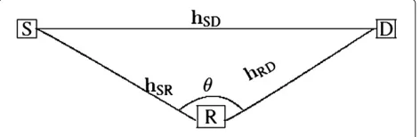
A three-node cooperative system is illustrated in Figure 1. The relay node R assists transmission from the source node S to the destination D. Each node is equipped with a single antenna and operates in a half-duplex mode. The transmissions and receptions are not carried out simul-taneously. An orthogonal AF relaying strategy is applied, whereby the source node first transmits to the destina-tion and the relay node (broadcasting phase), and then the relay node forwards a scaled noisy version of the signal received and the source node is silent (relaying phase).
The underlying channels are modeled as frequency-selective Rayleigh fading with a uniform delay profile. To overcome the ISI in frequency-selective channels, we apply the OFDM scheme to the relay system, which con-verts the frequency-selective fading channel into a num-ber of parallel frequency-flat channels free of ISI. An aggregate channel model consisting of both long-term path loss and short-term fading effects is considered. The path loss is proportional to d−γ, where d is the prop-agation distance and γ is the path loss exponent. By normalizing the path loss in the source-to-destination (S→D) link to be unity, the relative gains from source-to-relay (S→R), and from the relay-to-destination (R→D)
links are defined, respectively, asKSR = (dSD/dSR)γ and and hSD are independent identically distributed (i.i.d) zero-mean CSCG random variables with variances of 1/LSR, 1/LRD, and 1/LSD, respectively. The underlying channels are modeled as quasi-static Rayleigh fading, whereas the CIRs remain constant in the duration of one OFDM block and change to independent values that hold for another block.
To avoid the inter-block interference for the OFDM sys-tem, a cyclic prefix of length max(LSD,LSR,LRD)− 1 is applied. After the cyclic prefix is removed at the receivers, the length of the OFDM block is denoted byQ (which is also the number of subcarriers in one OFDM block). We assume that both relay and destination nodes are equipped with channel estimators. The relay node obtains an estimate of the CIR from the S→R link through train-ing symbols and feed-forwards this information to the destination. The relay node also transmits “clean” train-ing symbols so that the CIR for the R→D link can be obtained at the destination.aIn [20], it is proven that the minimum length of training symbols required for a non-cooperative OFDM system equals the channel length, and the optimal placement is that the training symbols are periodically inserted in each OFDM block. In this article, we adopt a similar channel training strategy. The number of training symbols is chosen as the maximum channel length among the links, i.e., N = max(LSD,LSR,LRD), where N is the number of training symbols. The num-ber of subcarriers in an OFDM block is chosen asQ = (M+1)N, withM≥1 being an integer. The training sym-bols are placed periodically at positions i = 1+(− 1)(M+1),=1,. . .,Nin the OFDM block.
Let the vectors xS = [xS(1),xS(2),. . .,xS(N)]T and
xR = [xR(1),xR(2),. . .,xR(N)]T denote, respectively,
the training symbols transmitted from the source and relay nodes. The data symbols are collected in vector y = y(1),y(2),. . .,y(MN)T. With the train-ing symbols periodically inserted, an OFDM block transmitted from the source node is expressed as
xS(1),y(1),y(2),. . .,y(M),xS(2),y(M+1),. . .,y(2M),. . .,
xS(N),y((N−1)M+1) . . .,y(MN)
. Let PS and
PR denote, respectively, the available power at the
source and relay nodes. Assuming that the train-ing symbols are independent of the data symbols, we define PS = (M+11)N(xHSxS + E[yHy]), and
PR = (M+11)N(xHRxR+E[wHRwR]), wherewHR is the sig-nal vector forwarded from the relay node. The power allocated in training and data transmission phases at
the source and relay nodes can individually be written asxHSxS/N = αtPS,E[yHy]/(MN) = αdPS,xHRxR/N = βtPR, andE[wHRwR]/(MN)= βdPR, whereαt,αd,βt, and βdare, respectively, the power allocation factors deployed at the source and the relay node, and they are related by αt+Mαd=M+1 andβt+Mβd=M+1.
2.1 Training phase
Let the diagonal matrix GAB denote the frequency response in the link A→B. Theqth diagonal entry is given
byGAB(q)=
LAB
k=1
hAB(k)exp(−j2π(k−1)(q−1)/Q), q=
1, 2,. . .,Q, where LAB is the channel length. Since the training symbols are placed periodically in each OFDM block at positionsi =1+(−1)(M+1),=1,. . .,N, theth frequency response in the training phase for link A→B is equal toGAB(i), and the received vector in the S→D link during the training phase can be expressed as
⎛ random variable at the destination in theith received fre-quency response. The frefre-quency response matrix in (1) is also written as, diag[GAB(1),GAB(2),. . .,GAB(N)]= GAB, andis a selection matrix of sizeN×Q[20] with theith row equal to theith row of the identity matrixIQ.
Let the diagonal matrixXS=diag(xS)consist of the train-ing symbols at the source node; then the received signals in (1) are further written in a matrix form as
zSD=XSVSDhSD+nt (2)
where zSD =[zSD(1),zSD(2),. . .,zSD(N)]T, and nt = [n(1),n(2),. . .,n(N)]T∼ CN(0,σ2IN) is the noise
vector at the destination in the channel training for S→D link. Similarly, the received vectors in the channel training for S→R and R→D links have the following form
tor at the relay in the channel training for S→R link, and
the channel training for R→D link. We assume that the MMSE estimator is deployed in the channel estimation. InsertingKSD=1, the estimated CIRs for the A→B link
hAB−hABbe the estimation error for the channel gains in the A→B link. The error covariance matrix is thus given by
In the data transmission phase, the information sym-bols are first broadcasted to the destination and the relay node (broadcasting phase), and then the relay node for-wards a scaled received signals to the destination (relaying phase). The received vectors at the destination during the broadcasting and relaying phases are given, respectively, as at the relay node during the broadcasting phase, wd ∼ (0,σ2IMN) is the CSCG noise vector at the relay,
diago-nal matricesGSDd = ¯GSD,GSRd = ¯GSR, andGRDd =
¯
GRDdesignate, respectively, the frequency response for S→D, S→R, and R→D links in the data transmission phase,¯ is a selection matrix of sizeMN ×Qobtained by removing the rows infromIQ,Ais the amplification
coefficient at the relay node to guarantee that the power of the signal forwarded from the relay does not exceed the available power, andA =
at the destination during the broadcasting and relaying phases. From (7) and (8), the overall received vector at the destination in the data transmission phase is
r= Let the diagonal entries in GABC collect the estimated
frequency response in data transmission phase for the link A → B. The associated estimation error is there-fore obtained asGABC = GABC−GABC, whereGABC =
¯
GAB, and GAB is of size Q× Q, its diagonal elements designated as the estimated frequency response for the link A → B. From the channel estimate given in (5), the qth diagonal entry in GAB is given by GAB(q) =
LAB
k=1
hAB(k)exp(−j2π(k−1)(q−1)/Q), q = 1, 2,. . .,Q.
Organizing the estimation errors and noise components into one vector, the input–output relation in (9) is rewrit-ten as
, vector v collects the
channel estimation errors, additive Gaussian noise at the destination, and noise forwarded from the relay node, and it has the following form:
v=
3 Lower bound on the achievable rate
In this section, we derive a lower bound on the achievable rate for the cooperative OFDM system under considera-tion. The achievable rate for the training-aided system is given by [20,22],
C=max
p(y)I(r,
Gd;y) (12)
where p(y) is the probability distribution of y, and
I(r,D;y) denotes the mutual information between the observation r, channel estimates DSDd,GSRd, and GRDd, and data vector y. Since the statistical distribution of v
in the received vector is difficult to characterize, we seek a lower bound on the achievable rate. Following similar steps in obtaining a tight lower bound on the achievable rate for a non-cooperative multiple-input multiple-output system [22,23], a lower bound for (12) can be found by imposing assumptions that the input datayis i.i.d zero-mean Gaussian, and vectorvis Gaussian distributed with the same first- and second-order statistics that are speci-fied by the random vector in (11). The lower bound can be evaluated as Clb = Q1E
log detI+R−v1GdRyGHd
whereRy =E[yyH]= αdPSIMN, andRv = E[vvH]. The
bound is further evaluated as
Clb=
where the expectation is with respect to the random vari-ables inGSDd,GSRd, andGRDd, matricesRv1 andRvi are, respectively, the autocorrelation ofv1andv2,
Rv1 =E[GSDdyyHGHSDd]+E[ndnHd]
The matrices in (14) and (15) are diagonal. The lower bound on the training-based achievable rate in (13) becomes the variance of the diagonal entries inGABd is identical for a specified A→B link. Assuming each training sym-bol has identical power, the variance of the ith diagonal entry in GSDd,GSRd, and GRDd are therefore expressed, are thus i.i.d. CSCG random variables for alli, due to the deployed MMSE estimation. We have
and (22) into (15), the covariance matrices ofv1andv2are given, respectively, by
The following normalized CSCG random variables are introduced as (16) is further evaluated by,
Clb=
M
M+1E
log1+B1x+B2yz (23)
wherex,y, andzare exponentially distributed, with prob-ability density functions given bye−x,e−y, ande−z, respec-tively,B1andB2are expressed as
andgk,k=1,. . ., 5 are given as
g1=(MN−LSD)JS,g2=(M+MJS+JS)LSD
g3= −KSRKRD2 αdJR2JSLSRN−KRD2 JR2N(αtJSKSRN+LSR)
g4= −KSRKRDJRαdJS(LSRLRD+αtJSKSRLRDN)
+KSRKRD2 αdJR2JSLSRN(M+1)
+(αtJSKSRN+LSR)
KRD2 JR2N(M+1)
+MNKRDJRKSRαdJS+MNKRDJR−LRDKRDJR)
g5=KSRKRDJRαdJS(LSRLRD+αtJSKSRLRDN) (M+1)
+(αtJSKSRN+LSR) (KRDJR(M+1)
+MKSRαdJS+M)LRD
(26)
4 Power allocation
In this section, we aim to find the power allocation fac-tors between the training and data transmission phases at the source and relay nodes to maximize the derived bound on the achievable rate. Since the power allocation factors in the data transmission phases (αdandβd) can be expressed as functions of the power allocation factors in training phase (αtandβt), we can obtain optimalαtand βtby solving the following optimization problem
(α˘t,β˘t)=arg max ˘ αt,β˘t
Clb (27)
It seems difficult to obtain a closed-form expression for the integral in (27). However, by noting that the integrand required for expectation in (23) is monotonically increas-ing withB1for fixedB2and vice versa, we can resort to a suboptimal solution by maximizingB1andB2separately. From (24), B1 is not a function ofβtand is convex with respect toαt, which can readily be determined by
check-ing d2B1 dα2
t <
0. The optimal value forαtto maximizeB1is then given by
ˇ
αt= 1
g1
−g2+
g22+g1g2(M+1)
(28)
On the other hand, B2 is convex with respect to βt ,
i.e., d2B2 dβ2
t <
0. Inserting (28) into (25), a suboptimalβtto
maximizeB2can be obtained by
βt0=
−g5+
g52+g5(M+1)g3(M+1)+g4
g3(M+1)+g4
αt= ˇαt (29)
5 Lower bound on the achievable rate and power allocation for the case of cascaded channel estimation
So far, we have assumed that both relay and destina-tion nodes are equipped with channel estimators and the
channel estimates in S→R and R→D links are obtained, respectively, by the training symbols sent at the source and the relay nodes. In this section, we assume that only the destination is equipped with a channel estimator. There-fore, it is the duty of the destination to obtain an estimate of the overall relaying S→R→D link using the training symbols sent from the source. In describing this alterna-tive scheme, we try to use the same variables, whenever possible, as in prior sections, or we use (ˇ·) whenever necessary.
Inserting the training symbols periodically (similar placement as in prior discussion), the OFDM block transmitted at the source node is written as d =
xS(1),y(1),y(2),. . .,y(M),xS(2),y(M+1),. . .,y(2M),. . .,
xS(N),y
(Nˇ −1)M+1,. . .,y(MNˇ), wherexS(i),i=1, . . .,Nˇ are the training symbols. The power con-straint at the source is PS = (M+11)Nˇ(xHSxS +E[yHy]),
xHSxS/Nˇ = αtPS,E[yHy]/(MNˇ) = αdPS. To remove inter-block interference, a cyclic prefix is added at the beginning of the transmitted vectors at the source node. Letdwcpdenote the transmitted vector with cyclic prefix, the length of which isQˇ +Lcp, whereQˇ = (M+1)Nˇ is the total length of training symbols and data information (length of vectord),Lcpis the length of the cyclic prefix, and “wcp” stands for “with cyclic prefix.” The received signal at the relay can be expressed as√KSRhSR⊗dwcp, in addition to the noise at relay, where⊗denotes the opera-tion of convoluopera-tion. Scaling the received signal by factor
ˇ
A =
Pr
(Qˇ+Lcp)
KSR(Nˇαt+MNˇαd)PS+σ2
, the relay forwards
the signal to the destination. The received signal at the destination is, therefore, Aˇ√KSRKRDhRD ⊗hSR ⊗dwcp and subject to the noise forwarded by the relay and noise at the destination.
The overall convolution channel in the relaying link S→R→D ishSRD = hSR⊗hRD, the length of which is
LSRD = LSR+ LRD − 1. The minimum length for the cyclic prefix in order to avoid inter-block interference is min(Lcp)=max(LSD,LSRD)−1. Removing the cyclic pre-fix and taking FFT, the received OFDM block (including training and data transmission phases) at the destina-tion isAˇ√KSRKRDGSRDd, plus the noise forwarded from the relay and noise at the destination, whereGSRDis the diagonal matrix of frequency response, and theqth
diag-onal entryGSRD(q) =
LSRD
k=1
hSRD(k)exp(−j2π(k−1)(q−
1)/Qˇ), q=1, 2,. . .,Qˇ.The estimate of the overall relaying channel is
hSRD=η
KSRRhSRDV H SRDTXHS ×η2K
SRXSVSRDRSRDVSRDH TXHS +σ2I
−1
whereη = √KRDA˘,RhSRD = E[hSRDhHSRD] ,zSRD = d,
is the selection matrix collectingi=1+(−1)(M+
1),i = 1,. . .,Nˇ rows fromIQˇ. LethSRD = hSRD−hSRD denote the channel estimate error for the relaying link. The error covariance matrix RhSRD = E[hSRDhHSRD] is diagonal with theith diagonal entry given by
RhSRD(i)= RhSRD(i) 1+η2KSRNαtJsσ2R
hSRD(i)
(31)
where RhSRD(i) is theith diagonal entry in RhSRD. Orga-nizing the channel estimate errors and noise components into vector f, the received signals at the destination is written as
Since the overall cascaded channel is no longer Gaus-sian, the derivation of a lower bound on the achievable rate for the system in (32) is intractable, as discussed in [24]. However, an approximate lower bound can be found by imposing similar assumptions as in [22,23]. Specifically, assuming that the input datayare i.i.d zero-mean Gaus-sian, and vectorfis Gaussian distributed with the same first- and second-order statistics specified by the random vector in (33), we obtain an approximation of the bound as follows:Cˇlb≈ Q1˘E
ing the determinant, the approximation of the bound is further expressed as
The matrices in (34) are all diagonal, with Rf1 =
Rv1,Rf2 =η2KSRαdPSE[GSRDdGHSRDd]+(η2+1)σ2I. The
There seems no analytical solutions to the power alloca-tion factorsαtandαdto maximize (36). The solutions can be obtained by maximizing the bound numerically.
6 Numerical results
In this section, we present numerical results to elabo-rate the derived bound on the achievable elabo-rate and the possible improvements through the proposed power allo-cation schemes. Unless specified otherwise, the plots are obtained for the disintegrated channel estimation scheme described in Section 2.1. For simplicity, the angle between links S→R and R→D in the relay system is chosen as θ =60◦, and the relay is located at equal distance from the source and the destination, except for the case where the effect of relay locations is considered. The following power allocation schemes for the training and data transmission are considered:
• The proposed power allocation (Proposed-PA) strategy, with the values ofα˘tandβ˘tgiven,
respectively, in (28) and (29).
• Uniform power allocation (Uniform-PA) with
αt=βt=1.
• Numerical power allocation (Numerical-PA), with the values ofαtandβtobtained by a numerically
exhaustive search to maximize the lower bound on the training-based achievable rate in (23).
6.1 Performance of power allocation schemes
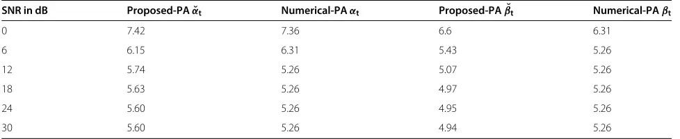
Table 1 lists the power allocation factors at the source and relay nodes by the Proposed-PA and Numerical-PA for different SNRs. The channel lengths are as follows:
LSD=4,LSR=LRD=3. The OFDM block length isQ=
Table 1 Comparison of the power allocation factors for Proposed-PA and Numerical-PA
SNR in dB Proposed-PAα˘t Numerical-PAαt Proposed-PAβ˘t Numerical-PAβt
0 7.42 7.36 6.6 6.31
6 6.15 6.31 5.43 5.26
12 5.74 5.26 5.07 5.26
18 5.63 5.26 4.97 5.26
24 5.60 5.26 4.95 5.26
30 5.60 5.26 4.94 5.26
The achievable rate of coherent OFDM relay system is thus given by
Ccoh=E
"
log det
I+(M+1)PS Mσ2 GSDdG
H
SDd
+ (M+1)KRDPSλ2coh
Mσ2
×GSRdGHSRd(λ2cohGRDdGHRDd+I)−1GRDdGHRDd
(37)
where a ratio (M + 1)/M is applied, because it is not necessary for the genie-aided coherent relay system to allocate power to the channel training. From Figure 2, we observe that the SNR gap between the Uniform-PA and coherent case is about 2.8–3 dB, and the achievable rate of the coherent transmission is 0.7–1.1 bits/s/Hz or 12–37% higher than that of the Uniform-PA. The Numerical-PA scheme reduces the gap by about 1.6 dB and provides 0.3–0.6 bits/s/Hz or 5–16% improvement for the bound on the achievable rate over the Uniform-PA scheme. It is also observed that the performance of the Proposed-PA scheme is almost identical to that of the Numerical-PA scheme.
0 5 10 15 20 25 30
0 1 2 3 4 5 6 7 8 9 10
SNR in dB
Lower bound on achievable rate (bit/s/Hz)
Coherent Numerical − PA Proposed − PA Uniform − PA
Numerical − PA (cascaded estimation) Uniform − PA(cascaded estimation)
Figure 2Comparison of Numerical-PA, Proposed-PA, and Uniform-PA schemes (Q=164).
To demonstrate the performance in the case of cascaded channel estimation described in Section 5, we obtain the power allocation factors by numerically maximizing the bound derived in (36) and plot the maximized bound. As shown in Figure 2, the curve is marked by “Proposed-PA (cascaded estimation).” In this case, the number of train-ing symbols is N = max(LSD,LSR + LRD) − 1 = 5, and the OFDM block length is chosen as 205. The bound in (36) with uniform power allocation αt = 1 is also
included, marked by “Uniform-PA (cascaded estimation).” It can been observed that, with appropriate power allo-cation factors, the lower bounds on the achievable rates remain almost the same, regardless of whether the chan-nel gains in the relaying link are estimated as two separate channels or as one overall channel.
In the following, we demonstrate the impact of some practical parameters such as OFDM block length, relay location, and channel lengths on the bound of the achiev-able rate.
6.2 OFDM block length
In Figure 3, we investigate how the length of OFDM block impacts the derived bound on the achievable rate
0 50 100 150 200 250
2 2.2 2.4 2.6 2.8 3 3.2 3.4 3.6
Total block length
Lower bound on achievable rate (bit/s/Hz)
Coherent Numerical − PA Proposed − PA Uniform − PA
for SNR = 10 dB. Plots indicate that the Proposed-PA and Numerical-PA schemes are consistently better than the Uniform-PA scheme regardless of the block lengths.
6.3 Relay location
In Figure 4, we investigate the effect of relay location on the derived bound. The level of SNR is fixed at 10 dB. The ratio KSRD = KSR/KRD (in dB) is introduced to reflect the relative relay locations. The more negative this ratio in dB, the closer the relay is placed to the des-tination. On the other hand, positive dB values of this ratio indicate that the relay node is closer to the source. The plots in Figure 4 suggest that the cooperative system achieves higher lower bounds when the relay is close to the destination. The Proposed-PA scheme can provide an improvement of 17–19% on the bound, in comparison to that of the Uniform-PA scheme depending on the relay location.
6.4 Channel lengths
In Figure 5, we investigate the effect of channel lengths on the achievable rate. We consider the following three scenarios:
• Scenario 1:LSD=30, LSR=3,LRD=3
• Scenario 2:LSD=3, LSR=30, LRD=3
• Scenario 3:LSD=3, LSR=3, LRD=30
For these channel configurations, the number of pilot symbols increased toN =max(LRD,LRD,LRD) =30. We choose the block length Q = 30(M+1) = 150 with
M= 4, and SNR =10 dB. It can be observed that the sys-tem achieves almost the same bounds for Scenarios 2 and 3, and a little less for Scenario 1. These can be explained through the values ofB1andB2. One can observe from
−30 −20 −10 0 10 20 30 2.6
2.8 3 3.2 3.4 3.6 3.8 4 4.2
KSRD in dB
Lower bound on achievable rate (bit/s/Hz)
Coherent Numerical − PA Proposed − PA Uniform − PA
Figure 4Effect of relay location on the bound of achievable rate.
0 5 10 15 20 25 30
0 1 2 3 4 5 6 7 8 9 10
SNR in dB
Lower bound on achievable rate (bit/s/Hz)
Coherent Numerical − PA Proposed − PA Uniform − PA
Scenario 2,3
Scenario 1
Figure 5Bound on achievable rate for different channel length combinations.
(24) and (25) that B1 and B2 capture, respectively, the equivalent SNR in the direct link and in the relaying link with imperfect channel gains. In Scenarios 2 and 3, B1 andB2 yield identical values, resulting in a similar per-formance for the mutual information. On the other hand, for Scenario 1, the value of B1 drops by 89% while B2 increases by 32%. The larger drop inB1results in a little more decrease of the bound in Scenario 1.
6.5 Channel estimate and power allocation
To illustrate the performance of the Proposed-PA scheme on channel estimates, we examine the mean square error (MSE) in the channel estimate with and without power allocations. Figure 6 plots the MSE of channel estimate
0 5 10 15 20 25 30 10−5
10−4 10−3 10−2 10−1 100
SNR in dB
MSE of channel estimate
Proposed − PA Uniform − PA
for the S→D link using the Proposed-PA and Uniform-PA schemes. The number of training symbols isN = 4, and the OFDM block length isQ = 164. Plots indicate that the Proposed-PA scheme provides about 7 dB SNR gain over the Uniform-PA scheme. Smaller errors in the chan-nel estimate help improve the training-based achievable rates for the Proposed-PA scheme.
7 Conclusion
In this article, we have investigated the achievable rates for a single-relay OFDM system with imperfect channel estimation. We first obtained a lower bound on the achiev-able rate and then used this bound to optimally allocate power between the training and data transmission phases. Since the optimum solution does not yield a closed-form expression, we proposed a suboptimal scheme by sequen-tially maximizing the terms in the integrand of the lower bound. Monte Carlo simulations demonstrate that the proposed power allocation scheme brings improvements of 5–19% depending on the SNR and relay locations in the bound on achievable rate, depending on the relay location and level of SNR.
8 Endnote
a In Section 5, we will further consider an alternative
scheme in which only the destination is equipped with a channel estimator and therefore the overall cascaded channel is estimated.
Competing interests
The authors declare that they have no competing interests.
Author details
1Department of Electrical Engineering and Computer Science, Wichita State
University, 1845 Fairmount, Wichita, KS 67260, USA.2Faculty of Engineering,
Ozyegin University Istanbul, Istanbul, Turkey.
Received: 5 September 2011 Accepted: 21 November 2012 Published: 31 December 2012
References
1. A Sendonaris, E Erkip, B Aazhang, User cooperation diversity—Part I: system description. IEEE Trans. Commun.51, 1927–1938 (2003) 2. K Azarian, H El Gamal, P Schniter, On the achievable diversity-multiplexing
tradeoff in half-duplex cooperative channels. IEEE Trans. Inf. Theory.
51, 4152–4172 (2005)
3. JN Laneman, DNC Tse, GW Wornell, Cooperative diversity in wireless networks: Efficient protocols and outage behavior. IEEE Trans. Inf. Theory.
50, 3062–3080 (2004)
4. M Gastpar, M Vetterli,On the capacity of wireless networks: the relay case, vol. 3, (New York, June 2002), pp. 1577–1586
5. RU Nabar, H B ¨olcskei, FW Kneub ¨uhler, Fading relay channel: performance limits and space-time signal design. IEEE J. Sel. Areas Commun.
22, 1099–1109 (2004)
6. A El Gamal, S Zahedi, Capacity of a class of relay channels with orthogonal components. IEEE Trans. Inf. Theory.51(5), 1815–1817 (2005)
7. B Wong, J Zhang, A Host-Madsen, On the capacity of MIMO relay channels. IEEE Trans. Inf. Theory.51(1), 29–43 (2005)
8. H B ¨ockei, RU Nabar, O Oyman, AJ Paulraj, Capacity scaling laws in MIMO relay networks. IEEE Trans. Wirel. Commun.5, 1433–1443 (2006) 9. I Mari´c, RD Yates, inThe 38th Asilomar Conference on Signals, Systems and
Computers. bandwidth and power allocaiton for cooperative startegies in
Gaussian realy networks, (Pacific Grove, CA, USA, November 2004), pp. 1907–1911
10. X Deng, AM Haimovich, Power allocation for cooperative relaying in wireless networks. IEEE Commun. Lett.9(11), 994–996 (2005) 11. J Zhang, MC Gursoy, Achievable rates and resource allocation strategies
for imperfectly-known fading relay channels. EURASIP J. Wirel. Commun. Netw.2009(2009)
12. O-S Shin, A Chan, HT Kung, V Tarokh, Design of an OFDM co-operative diversity system. IEEE Trans. Veh. Technol.56(4), 2203–2215 (2007) 13. I Hammerstrom, A Wittneben, Power allocation schemes for
amplify-and-forward MIMO-OFDM relay links. IEEE Trans. Wirel. Commun.
8(8), 4507–4512 (2007)
14. H Mheidat, M Uysal, N Al-Dhahir, Equalization techniques for distributed space-time block codes with amplify-and-forward relaying. IEEE Trans. Signal Process.55(5), 1839–1852 (2007)
15. Y Ma, N Yi, R Tafazolli, Bit and power loading for OFDM-based three-node relaying communications. IEEE Trans. Signal Process.
56(7), 3236–3247 (2008)
16. M Ibrahimi, B Liang, inProceedings of the IEEE International Conference on Communication (ICC). Efficient power allocation in cooperative OFDM system with channel variation, (Beijing, China, May 2008), pp. 3022–3028 17. O Amin, M Uysal, Optimal bit and power loading for amplify-and-forward
cooperative OFDM systems. IEEE Trans. Wirel. Commun.
10(3), 772–781 (2011)
18. J-H Wang, Y-B Lin, YT Su, inProceedings of the IEEE Signal Processing Workshop in Signal Advances in Wireless Communication (SPAWC). Resource allocation and relay selection for cooperative OFDMA networks with imperfect channel information, (San Francisco, June 2011), pp. 286–290 19. H Ochiai, P Mitran, V Tarokh, Variable-rate two-phase collaborative
communication protocols for wireless networks. IEEE Trans. Inf. Theory.
52(9), 4299–4313 (2006)
20. S Adireddy, L Tong, H Viswanathan, Optimal placement of training for frequency-selective block-fading channels. IEEE Trans. Inf. Theory.
48(8), 2338–2353 (2002)
21. SM Kay,Fundamentals of Statistical Signal Processing, Volume I: Estimation Theory. (Prentice-Hall, Inc. , Upper Saddle River, NJ 07458, 1993) 22. B Hassibi, BM Hochwald, How much training is needed in
multiple-antenna wireless links?. IEEE Trans, Inf. Theory.
49(4), 951–963 (2003)
23. TM Cover, JA Thomas,Elements of Information Theory. (Wiley, New York, 1991)
24. TA Lamahewa, P Sadeghi, X Zhou, On lower bounding the information capacity of amplify and forward wireless relay channels with channel estimation errors. IEEE Trans. Wirel. Commun.10(7), 2075–2079 (2011)
doi:10.1186/1687-1499-2012-372
Cite this article as:Ding and Uysal:Achievable data rates and power alloca-tion for frequency-selective fading relay channels with imperfect channel estimation.EURASIP Journal on Wireless Communications and Networking2012 2012:372.
Submit your manuscript to a
journal and benefi t from:
7Convenient online submission
7Rigorous peer review
7Immediate publication on acceptance
7Open access: articles freely available online
7High visibility within the fi eld
7Retaining the copyright to your article