in FDD transceivers
Robin Gerzaguet
1*, Laurent Ros
2, Fabrice Belvèze
3and Jean-Marc Brossier
2Abstract
This paper deals with the performance of the fractional delay estimator in the joint complex amplitude/delay estimation algorithm dedicated to digital Tx leakage compensation in FDD transceivers. Such transceivers suffer from transmitter-receiver signal leakage. Combined with non linearity of components in the receiver path, the baseband received signal is impaired by a baseband polluting signal. This baseband polluting term depends on the equivalent Tx leakage channel which models leakages of the receiver path. In (Gerzaguet et al., Digit. Signal Proc 51:35–46, 2016), we have proposed a Tx leakage interference cancellation algorithm based on joint estimation of the complex gain and the fractional delay of the equivalent Tx leakage channel and we have derived the asymptotic performance of the complex gain estimator, that showed the necessity of the fractional delay estimation. In this paper, we propose a comprehensive study of the fractional delay estimation algorithm and its analytic performance. The study is based on the analysis of the S-curve and loop noise variance of the timing error detector, from which an approximation of the asymptotic performance of the joint estimation algorithm is derived.
Keywords: Tx leakage, FDD transceiver, Digital compensation, Least-mean-square algorithm, Joint estimation, S-curve
1 Introduction
Cognitive radios offer the possibility to improve the spec-trum use and to adapt the transmission scheme to opti-mize the sharing of the available bandwidth, which leads to important constraints on the hardware components, located on the physical layer [1]. These constraints thus lead to performance limitations [2], and on this paper we focus on a hardware impairment that may occur in compact wireless transceivers when the radio follows a Frequency Division Duplexing (FDD) scheme. In FDD framework, transmission and reception are done simulta-neously, using two different carrier frequencies [3].
*Correspondence: [email protected]
This article is an extended version of the conference paper (Gerzaguet et al., Proc. International Conference on Cognitive Radio Oriented Wireless Networks (Crowncom), 2016) presented at the international conference Conference on Cognitive Radio Oriented Wireless Networks (Crowncom) 2016
1University of Rennes 1, IRISA, 38000 Grenoble, France Full list of author information is available at the end of the article
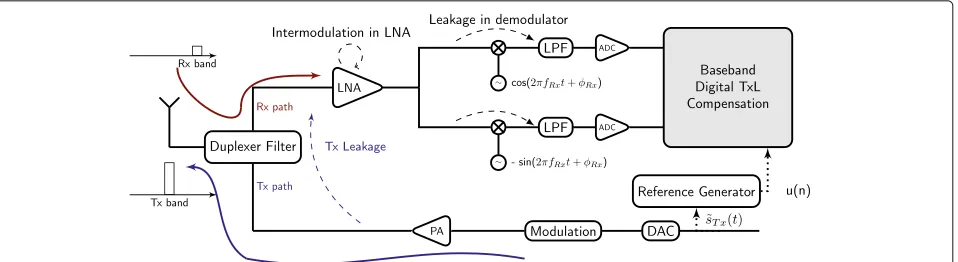
A surface acoustic wave (SAW) duplexer is often used to connect the received (Rx) and the transmitted (Tx) path to a common antenna [4] (see Fig. 1). As the duplexer does not provide infinite attenuation between the Rx path and the Tx path, the transmitted signal can leak into the Rx path [5] leading to the so-called Tx Leakage (TxL) phenomenon. As the uplink and the downlink bands are spectrally separated, the received signal will not be directly impaired by the leakage of the transmitted signal which is filtered by the Rx Low Pass Filter (LPF) after the demodulation.
However, due to the non linearity and imperfections of components in the analog Rx stage, especially the low noise amplifier (LNA) [6] and the demodulator [7], inter-modulation products can lead to a pollution in baseband. This polluting term corresponds to the square compo-nent of the Tx leakage signal, shifted to baseband [8]. As a consequence, this polluting signal will impair the received signal and can severely degrade the performance. The pol-lution is potentially detrimental in the cell edge context
Fig. 1Transceiver scheme. Classical frequency division duplexing chain in a RF transceiver with Tx leakage baseband pollution. The PA denotes the power amplifier, the ADC is the analog to digital converter, and the DAC denotes the digital to analog converter
(i.e., when the receiver is far from the base station), where the power of the received signal is low, and the power of the transmitted signal is strong [9] leading to a strong polluting signal and thus a low signal to interference ratio. To avoid this pollution, passive methods based on ana-log filtering can be implemented. Such mitigation meth-ods consist in adding a band pass filter to attenuate the leaked transmitted signal in the Rx stage before or after the LNA [10]. As radio frequency (RF) transceivers contain more and more digital parts, and as signal-processing techniques are becoming an area of interest for RF impairments problematic [11], several digital com-pensation methods have been investigated in the past few years for the Tx leakage (TxL) compensation [5, 9, 12].
In this paper, we complete the performance analysis of our previously proposed joint estimation (JE) algo-rithm dedicated to Tx leakage compensation [12, 13]. This algorithm estimates the equivalent TxL channel (approx-imated by a time varying complex gain and a fractional delay (FD)). It works with two reference-based least-mean-square (LMS) algorithms. As [13] and [12] mainly focus on the performance of the complex gain estima-tor (with and without a priori knowledge of the FD), we focus in this paper on the FD estimation part. The two main objectives, in addition to propose a comprehensive study, are (i) to prove that the FD estimation algorithm can lock around the desired FD value (ii) and to derive an approximation of the asymptotic performance of the JE algorithm.
The FD estimation algorithm has similitudes with data-aided algorithm that were designed for phase and timing synchronization as well as for automatic gain control or channel complex gain estimation [14]. However in the proposed estimation process, the received signal is sidered as noise, and an image of the Tx signal is con-sidered as a pilot sequence (used as reference). In this paper, as we focus on the FD estimator, we assume a
constant complex channel gain and we derive analytic formulae of the S-curve of the FD detector [14] (defined as the expectation of the so-called error signal that updates the FD estimation). A linear approximation of the esti-mation error variance of the FD stage is established as a function of the slope of the S-curve, which represents the gain of the equivalent timing-error detector. This result is finally used to derive an approximation of the asymptotic performance of the JE algorithm, in terms of signal to interference ratio (SIR), using the primary results obtained in [13].
This paper is organized as follows. We give the base-band polluting model in Section 2. We recall the joint estimation of the complex gain and the fractional delay in Section 3. We derive the performance of the frac-tional delay estimation algorithm in Section 4. Section 5 validates our method and theoretical results through sim-ulations.
2 Baseband model and issues
The discrete time observation model sampled at TRx
=1/FRxis expressed as
d(n)=x(n)+b(n)
xb(n)
+sTxL(n) (1)
where n is the time index, x(n) is the data-bearing sig-nal, which is assumed to be white and zero-mean with variance σx2, b(n) is the white additive Gaussian noise, of variance σb2, sTxL(n) is the TxL polluting signal and xb(n) = x(n)+ b(n) is then the desired (or expected)
noisy received signal without interference, with variance σ2
xb=σx2+σb2.
done in the literature [5, 15, 16] and modeled as a com-plex gain introduced by the coupling at the oscillator. We assume that the Rx filter is known (or estimated). Due to digital and analog blocks, the polluting signal has a delay , which is composed of an integer partDand a fractional partδ,=(D+δ)TRx. From (2), the polluting term can
be expressed as:
U(t) = hRx(t) |˜sTx(t)|2 (3) sTxL(n;) = βTxL(n)×[U(t−)]t=nTRx (4)
where βTxL(n) models the global TxL complex channel
gain at time index n (modeling the impact of both the duplexer and the demodulator leakage) assumed to be slowly varying w.r.t the sampling timeTRx. We have
pro-posed in [13] a TxL interference compensation based on two reference-based LMS algorithms that jointly esti-mates the complex gain and fractional delay of the TxL channel. The proposed algorithm can estimate time-varying parameters estimation, as presented in [12] with the tracking of the complex gain. We have shown that an optimal step-size for the complex gain estimation stage can be obtained. This optimal step-size depends on the time varying complex gain model. Since we focus in this paper on the static performance of the FD estimator, we assume a constant TxL channel for the theoretical analysis:
βTxL(n)=βTxL, ∀n
We also assume that the integer partDof the delay is known, as in practice it can be easily estimated with a cor-relation process or with a parallel structure, as described by [5], and without loss of generality, we takeD = 0. In [12], we have shown that the fractional delay cannot be neglected and we have proposed a joint estimation algo-rithm that is recalled in the next part. This structure is driven by a reference signalu(n), synthesized in the refer-ence generator (see Fig. 1 and (5)) from the baseband Tx samples, with the known or estimated Rx filterhRx:
u(n)=[U(t)]t=nTRx=hRx(t) |˜sTx(t)|2
t=nTRx (5)
One can see that the reference signalu(n)corresponds to the polluting signal withδ=0 andβTxL=1. It should
also be noted that, in practice, additional processing such
fractional delayδˆnand the complex gainβˆTxL(n)in order
to delay and scale the referenceu(n)before it can be prop-erly subtracted to the observed signald(n)(see (1)). The structure of the joint estimation algorithm is described on Fig. 2. It is composed of two blocks, one dedicated to the complex gain estimation, with a classic one tap LMS approach and the other one with a fractional delay esti-mation with another LMS. At each iteration, the reference signal u(n) is delayed by the estimated FD δˆn with an
interpolation structure that can be for example a Farrow structure [17] that produces:
The fractional delay estimation algorithm is based on the minimisation of the instantaneous square error |e(n)|2. Finally, the joint estimation algorithm can be
plex gain estimation,μthe step-size of the complex gain estimator,L(n) = ∂βˆTxL(n)/∂δ andν, the constant step
size of the fractional delay estimator. It can be seen that this algorithm is recursive, online (as it provides a com-pensated output e(n) at each iteration), and with low complexity.
4 Performance of the FD estimation
Fig. 2Joint estimation framework for the TxL compensation
a delay-locked loop synchronization algorithm and its performance can be studied with the same approach as described in [14, 18]. Thus, the FD estimation algorithm is equivalent to a first order tracking loop algorithm (see Fig. 3) piloted by its delay error signal denotedeδˆn. The
sta-bility and the performance of the proposed FD estimation algorithm can be studied using classical error detector open-loop analysis tools.
The equivalent delay error detector provides a delay error signaleδˆ
nfunction of the delayδand of the estimate
ˆ
δn. Assuming fixed delayδand fixed estimateδˆn, the delay
error signal can be decomposed into the sum of the con-ditional expectationEeδˆ
n|ˆδn
and an additional random zero mean term. The first termScis denoted S-curve and
is function of the FD estimation error δˆ
n=δ− ˆδnand the second termNTis called loop noise and is denotedNT(n).
Sc( δˆn) = E
eδˆ n|ˆδn
NT(n) = eδˆn−Sc( δˆn)
According to (7c)-(7d), the S-curve can be expressed as
Sc(δ,δˆn)= |βTxL|2
−sinc(δ)+sinc(1−δ)
+sinc(δˆn)−sinc(1− ˆδn)
σ4
Tx (8)
where|βTxL|2corresponds to the power of the TxL
chan-nel, that is assumed to be known. If the delay error is small, it is possible to linearize the S-curve around its stable equilibrium point [19]:
Sc( δˆn)≈KD× δˆn (9)
where KD = |βTxL|2×σTx4 (withσTx2 the variance of the
transmitted samples) is the slope of the S-curve at the sta-ble equilibrium point. As KD > 0, the FD estimator is
stable around δ (i.e., the loop will lock within the range of FD). Besides, as Sc(0) = 0, the FD estimator is
unbi-ased. Assuming a white loop noise for small FD error, the variance of the FD estimation stage can be derived as [14]:
σ2 δ =
ν
KD(2−νKD)NT
[ 0] (10)
Some interpretations and remarks can be done from (12):
• Since the fractional delay is constant, the variance of the fractional delay estimation converges to zero when the step-sizeνtends toward to zero. In practice, decreasing the step-size would decrease the estimation variance but would also lead to a longer transient state before convergence.
• The variance is proportional to the power of the noisy received signalσxb2 =σ2
x +σb2. This has to be
taken into account when using the algorithm in practical case. In the simulation part (see Section 5), the step-sizeνis thus normalized by the power of the noisy signal. The presence of the noisy signal acts as a perturbation for the fractional delay estimation. If the entry signal would only the Tx polluting term, the fractional delay estimation would be straightforward. • A stability condition can be deduced from (12)
ν <1/σTx4 |βTxL|2
.
In [13], we have derived the performance of the complex gain estimator (assuming a constant TxL channel), in pres-ence of a non compensated FD. The performance have been assessed in terms of signal to interference ratio (SIR) of the complex gain estimator. Based on these results, we can now express the performance of the JE algorithm, using the error signal defined in (7a) (i.e., the output of the compensation structure) and the variance of the FD estimator expressed in (12) :
SIRcomp=10log10
The argument in the−10log10function in (13) is
com-posed by the addition of three terms that limit the perfor-mance:
• The first one is related to the complex gain estimation stage. If the step-sizeμof the complex gain algorithm is small, it can be approximated asμσu2/2.
pollution statistics
channel amplitude|βTxL|2
and noisy signal varianceσ2 xb
.
5 Simulations
The performance of the proposed algorithm, and more precisely, the performance of the FD estimation algorithm are further analyzed by simulations.
• On the Fig. 4, we first plot the theoretical, linearized theoretical, and simulated S-curve versus the estimation error of the FD estimator in open loop. It shows that the theory is corroborated and that the S-curve can be linearized when the estimation error is low (between−10and 10 percent of the sampling time). It also demonstrates that the FD estimation loop will lock and is unbiased asSc(0)=0.
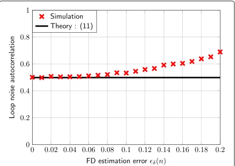
• On Fig. 5, we represent the theoretical and simulated loop noise zero-delay auto-correlationNT[ 0]versus the FD estimation error. When the FD estimation error is low, it can be seen that the assumption of a white loop noise with variance expressed in (11) leads to accurate results.
• On Fig. 6, the simulated delay error varianceσ2δis compared to the theory derived in (12). The curves are obtained for different fractional delay values and different normalized fractional delay estimator step-size values. One can see that the delay error variance is independent from the initial FD value and linear with respect to the FD step-size (for small step-sizeν); which is aligned with the theoretical equation derived in (12).
• On Fig. 7, we finally consider the performance of the JE algorithm considering the impact of the complex gain step-size. We consider that the data bearing signal is a white Gaussian signal polluted by a TxL signal that follows (4). The polluting SIR (i.e., the ratio between the power of the TxL polluting signal andσx2b) is set to 0 dB and the power of the desired noisy signal isσ2
x +σb2=10−8. The noisy data signal
Fig. 4Theoretical, simulated and linearized S-curve versus the FD estimation error
noisy signal (initial SIR of 0dB) due to the attenuation induced by the pollution. The complex gain algorithm is driven by a non interpolated referenceu(n)defined with (5) and the JE algorithm uses a Farrow structure to apply the estimated FD tou(n). We also assume a constant TxL channel, and we represent the
performance of the complex gain estimator and the JE algorithm for several values of FD. The FD estimation step-size is set toν=10−6/σxb2. The main objectives of this Figure are (i) show the impact of a non compensated fractional delay (ii) show the potential benefits of the FD estimation (iii) demonstrates that the theoretical performance (13) corroborates with the simulated results. We indeed show that the performance can be dramatically reduced if the FD estimation algorithm is not enabled. Besides, the JE algorithm greatly improves the asymptotic performance. If there is no FD and the FD estimation stage is disabled, the performance
Fig. 5Theoretical and simulated zero-delay autocorrelation of loop noise versus estimation error of the FD estimator
Fig. 6Theoretical and simulated error delay variance versus the fractional delay estimator step-size
becomes linear w.r.t the complex gain step-sizeμ(for smallμ) as, in this case, (13) becomes
−10 logμσ2
u/(2−μσu2)
.
If there is no FD but the JE scheme is enabled, one can see a performance floor at around 60 dB when the complex gain estimation step-size tends toward to zero. This is due to the residual error introduced with the FD estimation stage. From (12) and (13), withμ=0, the asymptotic SIR for the JE becomes
SIRcomp= −10 log
ν|βTxL|2
41−νσTx4 |βTxL|2
.
We can finally conclude that the asymptotic performance of the structure can be well
approximated and interpreted with (13); leading to a direct link between a desired asymptotic level and a step-size value for the FD estimatorν.
Fig. 7JE asymptotic performance. Asymptotic performance of the compensation algorithm for several values of the complex gain step-size and for different values of fractional delays for a fixed fractional delay step-sizeν=10−6/σ2
xb
performance when the FD stage is activated, and the corresponding theoretical expression derived in (13) is also represented. Is is shown that the asymptotic performance of the structure can be approximated with good accuracy with (13) leading to a direct link between a desired asymptotic performance level and step-size value for the FD estimatorν. If the step-size of the FD stage is high, the performance can be low as the variance of the stage (12) is proportional toνσxb2. In this case, the FD stage can be seen as a disruptive element for the complex gain stage. With a low step-sizeν, the performance is greatly enhanced (at the price of a longer transient state) and the performance converges to the performance of the complex gain without FD (first term of the theoretical expression derived in (13) as SIRcomp≈ −10log10
This paper deals with the performance of a joint esti-mation algorithm dedicated to the compensation of the digital Tx leakage in RF transceivers. The strong con-straints that apply to cognitive radios lead to a potential detrimental loss of performance due to hardware impair-ments and we focus here on a pollution that occurs in FDD transceivers, related to the pollution of an image of the transmitter stage on the receiver stage. Based on the initial algorithm proposed in [13], in this paper we focus on the fractional delay estimation algorithm that can be considered as a first-order tracking loop synchronisation algorithm piloted by an interpolated reference signal. We have firstly derived the analytical S-curve, defined as the conditional expectation of the error signal that controls the loop, and we have deduced an approximation of the asymptotic estimation error variance of the FD estimation algorithm. As the proposed approximated theoretical per-formance formula of the whole JE algorithm shows good accordance with simulations, this result can be used to properly tune the delay estimation algorithm step-size .
Funding
The authors declare that they have no funding sources.
Contributions
The two main objectives of the proposed paper, in addition to propose a comprehensive study on the Tx Leakage digital compensation, are (i) to prove that the initially proposed FD estimation algorithm can lock around the desired FD value (ii) and to derive an approximation of the asymptotic performance of the JE algorithm. This leads to a direct link between a desired asymptotic performance level for the compensation structure and a step-size value for the FD estimator
Competing interests
The authors declare that they have no competing interests.
Publisher’s Note
Springer Nature remains neutral with regard to jurisdictional claims in published maps and institutional affiliations.
Author details
1University of Rennes 1, IRISA, 38000 Grenoble, France.2GIPSA-Lab, Image and
signal department, 38400 Saint Martin d’Heres, France.3ST-Microelectronics,
38000 Grenoble, France.
Received: 27 October 2016 Accepted: 26 July 2017
References
1. D Cabric, RW Brodersen, inProc. IEEE 16th International Symposium on Personal, Indoor and Mobile Radio Communications (PIMRC). Physical layer design issues unique to cognitive radio systems, vol. 2, (2005), pp. 759–7632
2. H Tang, inFirst IEEE International Symposium on New Frontiers in Dynamic Spectrum Access Networks (DySPAN). Some physical layer issues of wide-band cognitive radio systems, (2005), pp. 151–159
3. H Martikainen, inProc. European Wireless Conference (EW). Analysis of duplexing modes in the IEEE 802.16 wireless system, (2010) 4. ME Knox, inProc. IEEE 13th Annual Wireless and Microwave Technology
Conference (WAMICON). Single antenna full duplex communications using a common carrier, (2012), pp. 1–6
5. A Frotzscher, G Fettweis, inProc. IEEE Vehicular Technology Conference (VTC). A stochastic gradient LMS algorithm for digital compensation of Tx leakage in Zero-IF-Receivers, (2008), pp. 1067–1071
6. B Razavi, Design considerations for direct-conversion receivers. IEEE Trans. Circ. Syst. (Analog Digit Signal Process).44, 428–435 (1997)
7. D Manstretta, M Brandolini, F Svelto, Second-order intermodulation mechanisms in CMOS downconverters. IEEE J. Solid-State Circ.38, 394–406 (2003)
8. C Lederer, M Huemer, inProc. IEEE International Conference on Wireless Information Technology and Systems (ICWITS). The influence of DC offsets on the digital cancellation of second-order Tx intermodulation distortions in homodyne receivers, (2012), pp. 1–4
9. A Kiayani, L Anttila, M Valkama, inProc IEEE 56th International Midwest Symposium on Circuits and Systems (MWSCAS). Modeling and dynamic cancellation of Tx-Rx leakage in FDD transceivers, (2013), pp. 1089–1094 10. K Dufrene, R Weigel, inThe European Conference on Wireless Technology.
Highly linear IQ downconverter for reconfigurable wireless receivers, (2005), pp. 19–22
11. G Fettweis, M Lohning, D Petrovic, M Windisch, P Zillmann, W Rave, in Proc. IEEE 16th International Symposium on Personal, Indoor and Mobile Radio Communications (PIMRC). Dirty RF: a new paradigm, (2005), pp. 2347–23554
12. R Gerzaguet, L Ros, F Belveze, J-M Brossier, Performance of a digital transmitter leakage LMS-based cancellation algorithm for multi-standard radio-frequency transceivers. Digit Signal Process.51, 35–46 (2016) 13. R Gerzaguet, L Ros, F Belveze, J-M Brossier, inProc. 21st International
Conference on Electronics Circuits and Systems (ICECS). Joint Estimation of Complex Gain and Fractional Delay for Tx Leakage Compensation in FDD Transceivers, (2014)
14. U Mengali, AN D’Andrea,Synchronization Techniques for Digital Receivers. Applications of Communications Theory(Springer, 1997)
15. M Faulkner, DC offset and IM2 removal in direct conversion receivers. IEE Proceedings on Communications.149(3), 179–184 (2002) 16. C Lederer, M Huemer, inProc. IEEE Radio and Wireless Symposium (RWS).
LMS based digital cancellation of second-order Tx intermodulation products in homodyne receivers, (2011), pp. 207–210
17. CW Farrow, inIEEE International Symposium on Circuits and Systems. A continuously variable digital delay element, (1988), pp. 2641–26453 18. E Simon, K Raoof, L Ros, inProc. IEEE International Conference on Acoustics,
Speech, and Signal Processing (ICASSP). Optimization of symbol timing recovery for multi-user ds-cdma receivers, vol. 4, (2003), pp. 604–74 19. H Meyr, M Moeneclaey, F S.A,Digital Communication Receivers(Proakis,