R E S E A R C H
Open Access
Generalizing and optimizing fractional
frequency reuse in broadband cellular radio
access networks
Lei Chen
1*and Di Yuan
1Abstract
For broadband cellular access based on orthogonal frequency division multiple access (OFDMA), fractional frequency reuse (FFR) is one of the key concepts for mitigating inter-cell interference and optimizing cell-edge performance. In standard FFR, the number of OFDMA sub-bands and the reuse factor are fixed. Whereas this works well for an idealized cell pattern, it is neither directly applicable nor adequate for real-life networks with irregular cell layouts. In this article, we consider a generalized FFR (GFFR) scheme to allow for flexibility in the total number of sub-bands as well as the number of sub-bands in each cell-edge zone, to enable network-adaptive FFR. In addition, the GFFR scheme takes power assignment in consideration. We formalize the complexity of the optimization problem, and develop an optimization algorithm based on local search to maximize the cell-edge throughput. Numerical results using networks with realistic radio propagation conditions demonstrate the applicability of the GFFR scheme in performance engineering of OFDMA networks.
Introduction
Orthogonal frequency division multiple access (OFDMA) is a current technology for broadband radio access. In OFDMA, the radio spectrum is split into a large number of channels, referred to as sub-carriers. Data transmission is performed simultaneously over multiple sub-carriers, each carrying a low-rate bit stream. OFDMA is very flexible in exploring multi-user diversity with high spec-trum efficiency and scalability. The technique is part of the downlink air interface in the fourth generation cel-lular systems based on 3GPP long term evolution (LTE) standards (see [1]), and IEEE 802.16 WiMAX (see [2]).
Orthogonal frequency division multiple access sub-carriers are orthogonal to each other. As a result, intra-cell interference is not present. Inter-intra-cell interference, on the other hand, becomes a performance-limiting factor. For this reason, interference mitigation has become an important topic in performance engineering of OFDMA networks.
*Correspondence: Lei.Chen@liu.se
1Department of Science and Technology, Campus Norrk¨oping, Link¨oping University, SE-60174, Norrk ¨oping, Sweden
Fractional frequency reuse
One sub-carrier allocation scheme in multi-cell OFDMA networks is frequency reuse with factor one (reuse-1), in which the entire spectrum is made available in all cells. Here and throughout the article, a reuse factor ofXmeans that the spectrum block in question is used in every group ofXcells. Users that benefit from the reuse-1 scheme are those located close to a base station antenna, i.e., users in the cell center. Because the channel condition is good and the interference from other cells is relatively low, the throughput in cell-center zones grows by bandwidth. For users located at cell-edge areas, however, the performance typically suffers severely in the reuse-1 scheme, because of the high interference from the surrounding cells in relation to the signal of the home cell. In other words, cell-edge zones are much more sensitive to interference than bandwidth. Previous studies (e.g., [3]) indicate that, if the overall system throughput is the only performance tar-get, then reuse-1 is the best choice. At the same time, the resulting performance in the cell-edge zones tends to be unacceptably low.
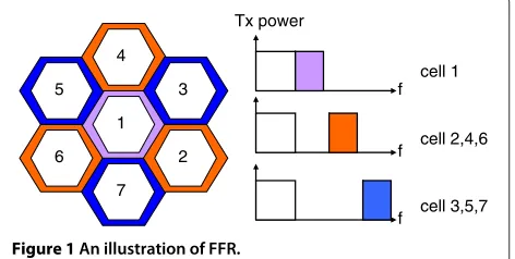
cell edge is fractional frequency reuse (FFR), see, for exam-ple, [4-6]. In FFR, the service area of every cell is split into a center zone and an edge zone. The spectrum is correspondingly partitioned into two parts. One part is allocated with reuse-1 in all cell-center zones. The second part is further split into sub-bands. These sub-bands, to be used in the cell-edges zones, have a higher reuse factor. As a result, significant interference reduction is achieved in cell-edge zones. In standard FFR, derived for an ideal net-work layout with hexagonally shaped cells, the edge band is split into three sub-bands, each with a reuse factor of three (reuse-3); every edge zone is allocated one of the three sub-bands, see Figure 1 for an illustration.
For the cell layout in Figure 1, the standard sub-band allocation pattern with reuse-3 is very intuitive. The allo-cation pattern ensures that the sub-band of a cell-edge zone is not reused in any of the neighboring cells. In real-life cellular networks, however, the amount of interference is very irregular over the service area. The cells differ greatly in the number of significant interferers as well as the respective amounts of interference, causing difficulties in applying standard FFR. As the number of surround-ing cells varies from one cell to another, allocatsurround-ing the sub-bands optimally is not straightforward. For the same reason, a single reuse factor, if applicable at all, is no longer optimal. In addition, because the sensitivity to interfer-ence varies by cell, the allocation of one sub-band per edge zone may not be adequate. Finally, scalability becomes an issue, because it is not optimal to replicate the allocation pattern of one part of the network to another.
A generalized FFR scheme
In this article we present and evaluate a generalized FFR (GFFR) scheme, in order to overcome the limitations of standard FFR in dealing with real-life networks with irregular cell layout. As a result, the allocation pattern is adapted to the characteristics of each individual network. The GFFR scheme that we consider extends the stan-dard one in three aspects. First, the frequency band used for cell-edge zones can be partitioned into any number of sub-bands. Doing so is potentially useful for interfer-ence avoidance in cells with many surrounding interfering
Tx power
Figure 1An illustration of FFR.
neighbors. Second, the number of sub-bands allocated to the edge zone is cell-specific. Having this flexibility is important when many sub-bands are created, since the cell-edge zones in real networks differ in their levels of sensitivity to interference respective spectrum bandwidth. Some edge zones may benefit from using few sub-bands which are not reused at all in the surrounding areas, whereas other edge zones can tolerate higher interference and consequently should be allocated more sub-bands with a higher reuse level. As the third extension of FFR, power assignment is part of the optimization framework of GFFR. In standard FFR, power is typically not a vari-able. The GFFR scheme allows the power to vary by cell, in order to achieve further gain in addition to that enabled by sub-band reuse optimization.
We focus on cell-edge user performance in this article. The performance metric that we use to assess sub-band allocation and power assignment targets throughput guar-antee in the cell-edge zones. In the system model (see Section “The system model”), the service area is repre-sented by a large number of pixels. For example, in one of the test network scenarios for performance evaluation (Section “Experimental results”), a pixel is a square area of size 20× 20 m. For each cell-edge pixel, the perfor-mance metric is defined by the data throughput that can be guaranteed when all the interfering cells are active. In effect, this metric corresponds to the average downlink throughput with uniformly distributed cell-edge users and round-robin scheduling, and provides a throughput map over the cell-edge areas. Note that, by associating pixels with non-uniform utility parameters, the metric is easily adapted to any given user distribution with uneven traffic demand.
Figure 2 gives an illustration of GFFR, in which the gran-ularity in creating sub-bands is high, and an edge zone may use multiple sub-bands. In addition, the power varies by cell. In the example, cell one has more edge sub-bands allocated than the other two cells, most likely because the edge zone of cell one is less interference-sensitive. At the same time, allocating more sub-bands to cell one results in higher interference to the other cells. Hence the allocation decision is based on the overall edge-zone throughput in the network. From this simple example, it is clear that allo-cating sub-bands and assigning power in GFFR amount to solving a combinatorial optimization problem.
Figure 2An illustration of the proposed GFFR scheme.
We formulate the task of sub-band allocation and power assignment as an optimization problem, and prove its complexity. A local search algorithm is developed for problem solution. The search in the algorithm is based on a neighborhood structure that finds the exact opti-mum of sub-band allocation and power assignment of one cell, provided that the solutions of the other cells are ten-tatively kept fixed. This single-cell optimization process is not straightforward, we show however that it can be implemented to run in polynomial time.
We use networks with realistic radio propagation con-ditions and very irregular cell layout for performance evaluation. The optimized allocation significantly goes beyond the performance of FFR with three sub-bands, which, in its turn, delivers better throughput than reuse-1 in cell-edge zones. The improvement that we obtain enables better trade-off between cell-center and cell-edge performance. In addition, the information required by the algorithm’s key operation can be restricted to be local to each cell. This observation forms a promising basis for developing distributed allocation algorithms.
Paper outline
The remainder of the article is organized as follows. In Section “Related works” we review related works and summarize the contributions of the current article. The system model and notation are given in Section “The system model”. In Section “The optimization problem and its complexity”, we formalize the optimization prob-lem and prove its complexity. The local search algorithm is detailed in Section “Solution algorithm”. We present and analyze experimental results in Section “Experimen-tal results”. Finally, Section “Conclusions” is devoted to conclusions and an outline of further research.
Related works
There is a growing amount of research on FFR and its per-formance evaluation. Simulations for assessing the perfor-mance of the standard FFR scheme have been conducted
in [11-14]. The main conclusion is that FFR is able to improve the performance at cell-edge zones. The impact of cell-edge size on throughput has been analyzed in [15]. In [16], an analytic model for estimating the throughput of FFR is presented. The idea of using analytic models instead of simulation to assess the signal-to-interference-and-noise ratio (SINR) for FFR is adopted also in [17]. In [18], it is shown that, if FFR is performed in a distributed fashion, and each cell selfishly optimizes the assignment of resource to its own users, the system will converge to a Nash equilibrium. Chang et al. [19] take a graph theoreti-cal approach and formulate FFR sub-band allocation as a graph coloring problem. In [20,21], FFR sub-band alloca-tion has been performed based on an interference graph connecting the base stations. The studies consider an ideal cell layout pattern in performance evaluation. Com-parative studies of FFR and other interference-mitigating schemes, in particular the soft frequency reuse (SFR) scheme, are provided in [22,23]. Simulation tools and architecture support for FFR are presented in [24,25]. The application of FFR and its performance evaluation in femto-cell environments are examined in [26-29].
For a given set of users, the problem of allocating resource at the sub-carrier level in FFR is formulated using mathematical optimization models in [30,31]. The con-straint in resource allocation is the minimum required user throughput. The solution approach is based on a relaxation of the original problem to obtain convex opti-mization formulations. A similar problem setting for OFDMA resource allocation is considered in [32], and solved using Lagrangian relaxation.
of the FFR pattern. The work in [37] validates a clustering-based FFR scheme. In [38], FFR is combined with inter-ference suppression for improving spectral efficiency and power expenditure. Rahman and Yanikomeroglu [39] pro-poses to perform FFR-based interference avoidance at two levels by base station and a central controller, respec-tively. The latter conducts inter-cell coordination. An FFR scheme based on generating reports of the interference levels among neighboring cells is presented in [40]. The work in [41] augments FFR by enabling adaptive spec-tral sharing, and proposes a graph-theoretical solution approach. In [8], Ali and Leung presents a two-level FFR scheme. At the RNC level, groups of sub-carriers are allocated to cells. Resource allocation to individual users is then performed opportunistically by base stations. In [42], Tara and Hakima proposes an FFR-based frequency planning scheme utilizing zone switching diversity for multi-cell mobile WiMAX networks.
The current article presents significant extensions to our preliminary studies of optimal FFR in large-scale networks with irregular cell layout [23,43]. The works reported in the two references have several limita-tions. First, no theoretical result in problem complexity is provided. Second, resource allocation of every edge zone is restricted to one single sub-band. Third, uni-form power is assumed in all cells. Fourth, the impact of the SINR threshold used to define cell edge is not considered. In the current article, we provide a for-mal proof of problem complexity and present a new optimization algorithm that overcomes the performance-limiting assumptions in [23,43]. In addition, we study how the cell-edge SINR threshold influences the perfor-mance.
A problem domain related to optimal FFR is frequency assignment in second generation cellular networks. In frequency assignment, the number of frequencies to be allocated to each cell is given. Typically, the objective is to minimize the total number of frequencies or to minimize the interference for a fixed set of available frequencies. For frequency assignment, we refer to the extensive surveys in [44,45] and the references therein, and [46,47] for gener-alizations of frequency assignment to frequency-hopping networks. In Section “The optimization problem and its complexity” we outline the structural differences between frequency assignment and GFFR.
Another related topic consists in the practical imple-mentation of FFR in OFDMA-based systems, such as LTE networks. Static and semi-static FFR implementa-tions have been discussed in [4,6,25], and dynamic FFR implementations have been investigated in [8,26,41]. By the flexibility of GFFR, it admits to be implemented both statically or dynamically. For example, GFFR can be implemented at the top level (e.g., the RNC level in the architecture proposed in [8]) in a hierarchical resource
management framework, with opportunistic resource allocation in the lower level.
Depending on the way of implementation (centralized, distributed, cluster based, etc.), information gathering and exchange are necessary at one or more levels in a network. The information required by GFFR does not differ from that in the previously proposed FFR implementations. For example, in a centralized scheduling scheme, such as the one at the top level in [8], the scheduler needs user channel state information to coordinate the resource allo-cation among cells. The same type of information would be gathered for GFFR. When implemented in a distributed manner, GFFR is able to, as was mentioned earlier, base its decisions on local information, provided that the neigh-boring cells coordinate the sequence of decision making. In such a case, the resource allocation status needs to be exchanged between eNodeBs. In LTE, this can be done through the standard X2 interface. To summarize, GFFR is a more generalized and enhanced version of FFR, and can be implemented as an integral part of the overall resource allocation scheme.
The system model
In this section, we first present the basic elements of the system model, along with introducing notation. Next, the power assignment scheme is discussed. We then present cell-edge throughput calculation for any given sub-band allocation and power assignment.
Preliminaries
We use C = {1,. . .,C} to denote the set of cells of an OFDMA network. The service area is represented by a regular grid of a large number of pixels J = {1,. . .,J}. Each pixel j ∈ J is a small square area within which radio propagation is considered uniform. We use gij to denote the total gain between the cell antenna ofi and pixel j. The gain value is typically obtained by measure-ments and/or prediction models of signal propagation. The service area of a cell is divided into a center zone and an edge zone. The latter represents locations that are prone to interference from the surrounding cells. Denote by Jie the set of pixels forming the edge area of celli. Note that, for real-life networks, the shape of cell edge is in general irregular, just like the cell layout. Moreover, it may happen that a cell does not have an edge zone. This occurs if the signal of the cell antenna is strong over the entire cell area. Merely for simplifying the notation, we assume that all cells have edge zones in our system modeling.
total bandwidth and the bandwidths allocated for center and edge zones by B, Bc, and Be, respectively, where
B=Bc+Be.
The cell-center band with bandwidth Bc is allocated with reuse-1 in all cell-center zones, which we do not dis-cuss further in the system model. The cell-edge band is split into equal-sized sub-bands. LetKdenote the number of edge sub-bands, andK= {1,. . .,K}. The bandwidth of each sub-band isBsub= BKe. Moreover, we useσjto denote the thermal noise effect in pixelj.
In GFFR, one or multiple sub-bands inKis allocated to each cell-edge zone. We represent the allocation pattern by a tuple of sets
c=(C1,. . .,Ck,. . .CK). (1)
In (1),Ckcontains the subset of cells being allocated sub-bandk. Clearly, each cell will appear in at least one of the set elements inc. For sub-band allocation patternc, we use Ni(c)to denote the number of sub-bands allocated to the edge zone of celli; this equals the number of set elements inccontaining celli.
Power assignment
We consider the common assumption of uniform power over the edge sub-bands in each cell. Under this assump-tion, the power used per sub-band in cell i is denoted by pi. This is an optimization variable, and its value is to be selected from a given discrete set of power levels {P1,P2,. . .,PL}. The power assignment is represented by the following vector.
p=(p1,. . .,pi,. . .,pC). (2)
The number of sub-bands of an edge zone can range between one and K in GFFR. As a result, the maximum value that pi can take depends on the number of sub-bands used in cell i. Without loss of generality, we assume that PL equals the total power available to any cell for its edge zone (i.e., this maximum can be reached on a sub-band, provided this is the only sub-band allocated in a cell), and set its value to be equal to the total cell power scaled by the edge bandwidth, i.e., PL =
PTotBe
B . Power assignment has to respect the con-straint that the product between pi and the num-ber of sub-bands allocated in cell i does not exceed PL. Thus for sub-band allocation pattern c, the candi-date sub-band power level of cell i becomes Li(c) = {1, 2,. . .,L}, where L is the largest integer such that PLNi(c)≤PL.
Cell-edge throughput
For sub-band allocation cand power assignmentp, the SINR of pixelj∈Jieon sub-bandk, for whichi∈Ck, has
In (3), the numerator is the received power from celli. The denominator accounts for interference from cells that reuse sub-bandk, and the noise effectσjin pixelj. Thus (3) gives the SINR value that can be guaranteed when all interfering cells on sub-bandkare active. The SINR can then be used to estimate the available throughput within pixelj, by means of a throughput function, denoted byf. The function is monotonous and increasing in SINR. One such function is the theoretical throughput limit given by the Shannon formula below.
f(SINRkij(c,p),j)=Bsublog2(1+SINRkij(c,p)) (4) It should be pointed out that neither our system model nor the optimization algorithm assumes the use of (4) as the throughput functionf. In fact, any empirical function taking into account adaptive modulation and coding can be used. The total achievable throughput atj, provided that the home cell is i, equals the sum of the function values over all allocated sub-bands, i.e.,
k:i∈Ck
f(SINRkij(c,p),j). (5)
The optimization problem and its complexity From the system model, the task of applying GFFR amounts to finding a sub-band allocationcand a power assignmentp, such that the overall throughput of the cell-edge areas is maximized. The optimization is subject to the conditions that each cell-edge zone is allocated at least one sub-band, and that the power used by the sub-bands together does not exceed the power limit in any cell. The optimization problem is formulated below.
max
Theorem 1. The sub-band allocation and power assign-ment problem defined by (6)–(8) is NP-hard.
Proof. The proof of the NP-hardness of problems,
or, NP-completeness of its decision version, involves a polynomial-time reduction from one of the well-known NP-complete problems. For our problem, we give a polynomial-time reduction from the vertex coloring prob-lem. Consider any instance of vertex coloring defined on graph G = (V,E). Letn = |V|. The decision problem is to determine, for a positive integerK > 1, whether or not there is a feasible coloring with at mostKcolors. We assume that n ≥ 3,K ≥ 3, andK < n, as otherwise determining the feasibility is trivial.
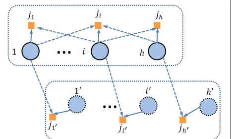
First, in this paragraph, we defines the key elements in constructing an instance of the GFFR optimization prob-lem. The set of cellsC = {1,. . .,n} ∪ {1,. . .,n}. All cells have one single edge pixel, denoted by ji for celli. The basic construction is illustrated in Figure 3. In the figure, the solid lines indicate the serving relation between cells and pixels. For anyi∈ {1,. . .,n}, celliis the only poten-tial interferer (i.e., having a positive gain value to pixelji). This is indicated by the dashed lines between the upper and lower parts of the figure. For anyi ∈ {1,. . .,n}, its neighbors in graph G are the potential interferers. For example, if nodesiandhare neighbors in graphG, theni is a potentially interfering cell ofjh, andhis a potentially interfering cell ofji. None of the cells 1. . .,n imposes interference to others. Consider a function of type (4), withBsub = 12. Without any loss of generality, assume the function can reach value one for some SINR. There are two power levels (L = 2), withP1 = PKL. As a result, the power per sub-band has to beP1, if a cell is allocated more than one sub-band. Note thatLis a constant in the proof, hence it is independent of the size of the vertex coloring problem.
The gain valuesgiji andgiji, and noise effectσjare set
such that the throughput over one sub-band at pixelji is 1.0, if the sub-band is not allocated to celliand the power
Figure 3An illustration of the underlying idea of the proof.
level in celliisP1. In this case, the signal-to-noise ratio inji is 3.0. If the sub-band is reused ini, the throughput ofji is 2n12K, if the power values arePL andP1in cellsi andi, respectively. For celli, the gain values of the poten-tially interfering cells (corresponding to some of the nodes in graph G) are set such that the throughput of ji over one sub-band is nK1 , if none of the potentially interfering cells reuses the sub-band and celliuses power levelP1. If reuse takes place, the throughput ofjiis at most2nK1 , even if cell i uses powerPL and there is only one interfering cell with powerP1. It can be realized that gain and noise values satisfying the above conditions can be constructed easily.
After setting the gain and noise values, we will show in this paragraph that, at optimum, any celli∈ {1,. . .,n}will use one single sub-band, whereas any celli ∈ {1,. . .,n} will use all the K sub-bands. Suppose it is optimal that celli uses multiple sub-bands (with powerP1 on each). We consider two scenarios. Assume first celliuses more than one sub-band (and thus also with powerP1on each). Keeping the power fixed at P1and supposing that cell i gives up any of the allocated sub-bands, the only cell expe-riencing lower throughput is i, and the loss is at most
1
nK. The throughput increase in cellion the sub-band is 1−2n12K or 1, depending on whether or not the sub-band is currently in use ini. Since 1− 2n12K = nK−21n
nK > nK1 , the sub-band removal operation leads to better overall performance, contradicting the assumption of optimality. Assume now that celliuses a single sub-band with power PL(usingP1is not optimal, because cellidoes not gen-erate interference to other cells, see Figure 3). Consider removing the sub-bands of i except one, and let i use all theK−1 interference-free sub-bands with powerP1. Before the modification, the throughput iniandiare at most(K−1)nK1 and12log2(1+3K)(because forithe SNR with powerP1is 3, andPL = KP1), respectively. Disre-garding the throughput in cellior potential performance improvement in any other cell, the new throughput ofi alone due to the modification is at leastK−1. Compar-ing K − 1 to(K −1)nK1 + 12log2(1+ 3K), the former is greater for any K ≥ 3, contradicting the optimality assumption. Therefore celliuses exactly one sub-band at optimum.
using all the K sub-bands is optimal in cell i. Con-sequently, the throughput of i at optimum is at least K − 1, and strictly below K − 1 + 2n12K (because the additional term can be reached only with power PL). The total throughput of {1,. . .,n} is in the interval
n(K−1),n(K−1)+ 2nK1 .
For cells 1,. . .,n, the total throughput reachesK1, if there is a feasible coloring inGwith no more thanKcolors. In this case, the overall throughput in the entire network is at leastn(K−1)+K1. If conflict in coloring has to take place between some nodes inG, the overall throughput of our problem instance is strictly less thann(K−1)+2nK1 +n−nK1+
1
2nK =n(K−1)+ 1
K. Thus the feasibility of the vertex col-oring instance is equivalent to whether or not the overall throughput of our problem instance reachesn(K−1)+K1. In addition, the reduction is clearly polynomial. Hence the decision problem of (6)–(8) isNP-complete, and the optimization problem itself isNP-hard.
To some extent, optimizing sub-band allocation in GFFR is similar to the frequency assignment problem (FAP) in second generation cellular networks. There are several versions of FAP, see [45]. The version that resem-bles most sub-band allocation in GFFR is minimum-interference (MI) FAP. Although both problems amount to allocating frequencies (or frequency bands) to cells, there are several structural aspects in which they differ significantly. First, the number of frequencies to be allo-cated to each cell is part of the input of FAP, whereas for GFFR it is a decision variable. Second, MI-FAP addresses interference between pairs of cells. In our case, in contrast, cell-edge throughput is in focus, and thus the pixels form-ing the service area are modeled explicitly. The third dif-ference lies in the non-linearity in the objective function (6). Due to these differences, solution algorithms devel-oped for FAP do not apply to sub-band allocation in GFFR.
Solution algorithm
In view of the problem complexity of (6)–(8), and the objective of applying GFFR to large-scale networks, we consider a local search algorithm aimed at finding high-quality solutions time-efficiently. A local search algo-rithm iteratively seeks solution improvement by repeat-edly introducing modifications to the current solution and evaluating the outcome. The search strategy is defined by the operation used in making trial modifications. Solu-tions generated by the modification operation are consid-ered neighbors to the current one, and the definition of the modification operation is also known as the neighborhood structure. The algorithm stops when no improvement can be obtained by solution modification, that is, the current solution is locally optimal in respect of its neighbor-hood. In this section, we present the design of the local
search algorithm, in particular the neighborhood struc-ture and how to time-efficiently evaluate the solutions in the neighborhood.
Initial solution
To obtain a starting solution, we apply a type of greedy algorithm that allocates one single sub-band to each cell. The algorithm goes through all cells 1,. . .,Cone by one. For each cell, the total throughput over the cell-edge pixels is computed for each of the sub-bands in{1,. . .,K}with the same power as reuse-1, and the sub-band leading to the highest throughput value is chosen. Once allocated a sub-band, the allocation for the cell in the initial solution is fixed when considering the remaining cells. In effect, the algorithm tends to select the sub-band for which the cell under consideration and the cells having the sub-band allocated have least interference to each other in the edge areas.
The amount of calculations in generating the initial solution is polynomial inCandK. Note that, with an ideal hexagonal cell layout, the starting solution will coincide with standard FFR ifK =3.
Search strategy
For (6)–(8), we will show that computing theexact opti-mumof sub-band allocation and power assignment of one cell can be performed in polynomial time, provided that the solutions of the remaining cells are tentatively kept fixed. Based on this result, we define the neighborhood structure as the set of alternative solutions obtained by optimizing the sub-band allocation and power assignment of one cell at a time. Among the neighboring solutions, the one having largest overall improvement is selected, and replaces the current solution. The search is repeated until the current allocation is locally optimal in every cell, i.e., no improvement can be reached by changing the allocation of any single cell.
Consider now the connection between sub-band allo-cation and power assignment. Changing the number of sub-bands in a cell may enlarge or shrink the set of candi-date levels in power assignment. Hence the computation does not decompose in the same way as above. As there areKm=1mKLmpotential allocation patterns, whereLm denotes the number of candidate power levels for m sub-bands, the amount of computation is seemingly expo-nential inK. We will show, however, that determining the global optimum can be implemented to run in polynomial time.
The idea is to, for each celli, go through the candidate numbers of sub-bands, and, for eachmbetween 1 andK, power levels 1,. . .,Lm. The overall number of combina-tions is polynomial inKandL. For each of these combina-tions, the computational task boils down to finding, for the given power level, thembest cell-edge sub-bands for celli. Toward this end, all sub-bands presently used in celliare removed first, so the cell’s sub-band allocation becomes empty. The throughput in cell i becomes zero, and the throughput of the remaining cells that use these sub-bands are updated. Next, for each sub-bandk ∈ {1,. . .,K}, the throughput of cell i on sub-bandk and the throughput loss in the other cells using this sub-band are computed. The values are put together as the performance value of sub-bandk. Note that this computation is not dependent on the allocation nor the throughput values of the other bands. Once the computation is complete for all sub-bands in{1,. . .,K}, them sub-bands giving the highest performance values form the optimum, provided that the number of sub-bands allocated to celliis restricted to be m. Repeating the procedure form = 1,. . .,K results in the global optimum of celli, assuming that the allocations in the other cells are unchanged.
The algorithm’s key steps can be summarized as follows. • Step 1: use current solution as the starting solution
and, for each cell, find the best number of sub-bands, together with the power allocation, provided that the solutions for the remaining cells are tentatively kept fixed.
• Step 2: calculate the throughput change for the current cell.
• Step 3: repeat Steps 1–2 for all cells.
• Step 4: find the largest throughput improvement among all cells.
• Step 5: if the throughput improvement in Step 4 is positive, use the corresponding solution to replace the starting solution. Go back to Step 1.
A formal description of the algorithm is provided in Algorithm 1. The initial solution consists in sub-band allo-cationcand power assignmentp. These are updated by local search and returned by the algorithm as the output.
For each cell considered in the main loop, the locally optimal solution (p∗,c∗) is initialized usingp and c, in lines 4–5. Thus the computations for the cells all start with the same solution. Then, sub-band removal in a cell is done in lines 6–11, resulting in a new temporary initial solutionc. The corresponding throughput of each sub-band in all cells using the sub-band is re-calculated and updated in line 10. The for-loop spanning lines 12– 36 considers the number of sub-bands to be allocated in the cell under consideration, and forms the bulk of the computation. For each numberm, another loop takes place over the corresponding candidate power levels (lines 13–35). For the power level under consideration, lines 15– 19 go through all sub-bands and calculate the throughput change over each sub-band if the sub-band is allocated to celli. This results in a throughput change vectorδ. Line 20 sorts the vector in descending order, resulting in a sorted vector δ and the corresponding index vector I. Line 21 calculates the sum of the m highest values in δ. If the sum improves over the currently best valueξ∗(initialized to zero), the optimal solution of the cell is updated (lines 22–34), and the cell is allocated the firstmsub-bands in the sorted sequence with the power level selected (lines 25–33). Once all cells have been considered after a major iteration, c and p are replaced by the best single-cell-optimized sub-band allocationc∗and power assignment p∗, respectively. The algorithm stops when an iteration does not produce any improvement (i.e.,ξ∗=0).
Algorithm 1 Local search
20: [I,δ]⇐sort decent(δk,(k=1, ...,K))
21: ξ⇐mk=1δk accumulate the
highestmthroughput changes
22: ifξ> ξ∗then update the currently best solution
23: ξ∗⇐ξ
24: p∗i ⇐pi
25: forh=1, ...,Kdo
26: ifh<mthen
27: l=Ih
28: Cl∗⇐Cl
29: else
30: l=Ih
31: Cl∗⇐ ¯Cl
32: end if
33: end for
34: end if
35: end for
36: end for
37: end for
38: c⇐c∗ update the best solution for one major iteration
39: p⇐p∗
40: untilξ∗=0return(c,p)
Experimental results
Test networks
We have conducted experiments using the data sets pro-vided by the European MOMENTUM Project (see [48]). The data contains real-life cellular network deployment scenarios in several European cities. The gain values in the data sets originate from real measurements. For per-formance evaluation of GFFR, the test data of Berlin and Lisbon have been used. The networks correspond to large scenarios with various user densities. Figure 4 illustrates
Figure 4Cell coverage pattern of the Berlin network.
the cell coverage pattern of the Berlin network. The area map consists in 22,500 pixels. The dots show base station locations, and the short lines denote the antenna direc-tions of the cells. The color of each pixel displays the number of cells providing coverage. As can be seen from the figure, the cells differ significantly in size and shape. Moreover, the number of neighboring and hence inter-fering cells varies greatly in the network. For this type of scenario, a sub-band and power allocation that is optimal for a sub-group of neighboring cells will hardly perform well in another part of the network. The observation motivates the application of the GFFR scheme.
The downlink bandwidth equals 4.5 MHz (i.e., the basic block of LTE). In the experiments, we useBc = 1.8 MHz andBe=2.7 MHz. Thus the cell-center areas lose 60% of the bandwidth in comparison to the reuse-1 scheme. The number of sub-bandsKvaries from 2 to 15.
Network parameters are summarized in Table 1. Cell edge is identified using a pilot-channel SINR threshold, and the performance results depend on the threshold value. To get a good picture of the impact of cell-edge definition on performance, we use and compare four threshold values for each network, see Table 1, such that the cell-edge zones form 3, 5, 7, and 10% of the total service area, respectively. For the Berlin network, the cor-responding SINR threshold values are−6.5,−5.8, −5.3, and−1.1 dB. For the Lisbon network, the values are−5.0, −4.4,−4.0, and−0.8 dB. As was discussed earlier, not all of the cells necessarily have cell-edge zone. We give the number of cells with edge zone in the table. Cell-edge throughput with reuse-1 is also presented in the table for comparison.
In Table 1, the cell total transmit powerPTotis 46 dBm, which corresponds to approximately 40 W. Since the cell-edge band takes 60% of the entire bandwidth, the total power over the edge sub-bands isPL=24 W. We require
Table 1 Network statistics and parameter setting
Berlin Lisbon
Area size (m2) 7500×7500 4200×5000
Number of cells 148 164
Area size (pixels) 22,500 52,500
Pixel size (m2) 50*50 20*20
Total DL Tx power (dBm)
46 46
Thermal noise (dBm) −107 −107
Cell-edge pilot SINR
threshold (dB) ≤ −
6.5/−5.8/
−5.3/−1.1 ≤ −
5.0/ − 4.4/
−4.0/−0.8
Number of cells with cell edge
64/83/109/124 128/147/158/161
Reuse-1 cell-edge throughput (Mbps)
2 3 4 5 6 7 8 9 10 11 12 13 14 15 0
0.5 1 1.5 2 2.5 3 3.5 4 4.5 5 5.5
Number of Sub−bands
Data Rate
3%: optimized 5%: optimized 7%: optimized 10%: optimized 3%: reuse−1 5%: reuse−1 7%: reuse−1 10%: reuse−1 (Mbps) Berlin Network
(K)
Figure 5GFFR cell-edge performance of the Berlin network.
that all cells allocate at least 0.1 W to cell edge (if any). The rest of the candidate power levels are created with a step size of 0.1 W.
The optimization algorithm is implemented in C++ and runs on a Dell E6410 notebook with an Intel Core i7 CPU (2.8 GHz) and 8 GB RAM. For each of the scenarios, we conduct 200 replications by changing the sequence of the cell during the generation of the initial solution. The results we present represent the average of the replica-tions.
Cell-edge performance
Figures 5 and 6 display the optimized average cell-edge throughput for various values of K, and compare the results to reuse-1. It is clear from the figures that the commonly used reuse-3 is not the best for an irregular cell layout. In the figures, the optimized GFFR perfor-mance tends to increase withK. This behavior is expected, because largerKgives better granularity in resource allo-cation. There is however no strict monotonicity. The reason is that the solution returned by the algorithm guar-antees a local optimum, which is not necessarily the global
optimal solution. In the two figures, the straight lines dis-play the throughput results of reuse-1. These results form a baseline for comparison. By definition, all sub-bands are allocated to cell edge as well as cell center in reuse-1. Therefore the performance is not dependent onK.
As can be seen from the figures, the optimization algo-rithm brings substantial throughput gain to cell edge in comparison to reuse-1. Taking the Berlin network and 5% cell edge as an example, the edge throughput grows from 1.2 to 4.5 Mbps for smallK, and further to 4.9 Mbps for some of the larger K values. Considering the Lis-bon network and the same percentage of edge area, the throughput is 1.7 Mbps with reuse-1, and lies between 3.4 and 4.1 Mbps for GFFR. Summarizing the results, the ranges of the improvement factor are [2.9, 4.7] and [2.0, 2.9] for the two networks, respectively, forK = 15. Here, the improvement factor refers to the ratio between the optimized GFFR throughput and that of reuse-1 in the cell-edge zones.
From the figures, it is apparent that the improvement decreases by the threshold value used to define the cell edge. Thus considering larger area as cell edge brings
2 3 4 5 6 7 8 9 10 11 12 13 14 15
0 0.5 1 1.5 2 2.5 3 3.5 4 4.5 5 5.5 6 6.5
Number of Sub−bands
Data Rate
3%: optimized 5%: optimized 7%: optimized 10%: optimized 3%: reuse−1 5%: reuse−1 7%: reuse−1 10%: reuse−1 (Mbps) Lisbon Network
(K)
Figure 7Performance comparison with [23,43].
down the average throughput. This is because a high threshold means that larger areas are considered cell edge, although parts of these areas are bandwidth-sensitive rather than interference-sensitive. The throughput loss of these bandwidth-sensitive users contributes significantly to the decrease of the average cell-edge throughput.
Our next part of performance evaluation compares GFFR with standard FFR and the results in [23,43]. Note that standard FFR will not perform better than GFFR with K = 3. As was discussed earlier (Section “Fractional fre-quency reuse”), for networks with irregular cell layout, standard FFR cannot be directly applied with a fixed fre-quency reuse pattern, e.g., reuse-3, because the number of neighboring cells varies greatly over the service area. Thus optimization is needed for the implementation of stan-dard FFR for our network scenarios. Our previous works [23,43] have been devoted to extending and optimizing standard FFR where the edge band can be partitioned into more than three sub-bands. Following the basic principle
Figure 8Illustration of the coverage pattern for a small scenario.
of standard FFR, strictly one sub-band can be allocated to each of the cell-edge zones in [23,43]. To demonstrate the strength of GFFR, in Figure 7 we provide a comparison between GFFR, standard FFR, and our previous works in [23,43] with 5% as the cell edge size.
From the figure, the improvement of GFFR over both standard FFR and [23,43] is apparent. Taking the Lisbon networks as an example, standard FFR withK=3 gives an average throughput of 2.44 Mbps. Applying the optimiza-tion algorithm in [23,43], which follows a search strategy being different from that of the current article, the average throughput result is 2.71 Mbps, giving an improvement of approximately 11% over standard FFR. GFFR has its strengths in providing the additional flexibility of power optimization as well as allowing multiple sub-bands in a cell-edge zone. For K = 3, GFFR yields an average throughput of 3.53 Mbps, outperforming standard FFR by 45% and the results of our previous works by 30%. ForK> 3, additional improvement is achieved. WithK =15, the corresponding GFFR throughput value is 4.10 Mbps, for which the relative improvement over standard FFR is 68%. Similar observations can be made for the Berlin network scenario. In conclusion, the merit of GFFR in comparison to standard FFR and [23,43] is significant.
2 3 4 5 6 7 8 9 10 11 12 13 14 15 0
2 4 6 8 10 12 14 16
Number of Sub−bands
CPU Seconds
3% 5% 7% 10%
(x1000s)
(K) Berlin Network
Figure 9Solution times for the Berlin network.
Figure 9 reports the computing times for the Berlin net-work. It is evident that the time grows fast in K as well as in the size of the cell-edge zone. In general, increas-ing K implies that more candidate allocation solutions must be evaluated in the search algorithm, and enlarg-ing the edge-area size leads to a higher number of pixels and hence more computations in throughput calculation. Putting the figures of throughput and computing time together, one can observe that whereas using a higher number of K makes the computing time grow rapidly, the additional performance gain is comparatively moder-ate. From our results, settingKbetween 3 and 6 achieves a good balance between the performance in through-put and comthrough-putational effort. In general, the choice of K depends on the network characteristics and finding a proper value is not trivial. In network planning, our algorithm can be applied to a subset of cell-edge pix-els, to provide fast performance evaluation and thereby suggestions on a proper sub-band division scheme. It is also worth remarking that the algorithm’s computing time is largely due to performance evaluation over the
Figure 10Cell-edge user throughput CDF plot for the Lisbon network.
entire area under consideration, for which all pixels are considered. For specific user distributions that typically involve a much smaller number of users than the num-ber of area pixels, the computing time becomes magnitude less.
Figures 10, 11 and 12 provide additional illustration comparing reuse-1 to GFFR for the Lisbon network with 5% of the areas being defined as cell edge. The cumulative distribution function (CDF) of cell-edge user throughput is present in Figure 10. The figure shows that about 40% of the cell-edge users have their through-put significantly improved. These users are the most interference-sensitive ones. Figures 11 and 12 display the cell-edge throughput map for reuse-1 and GFFR with
Figure 12Cell-edge throughput for the Lisbon network with GFFR (K=6).
K = 6, respectively. It is apparent that a large num-ber of cell-edge pixels achieve significant throughput increase.
Performance trade-off
Revisiting the results, it is clear that the improve-ment due to GFFR is strongly related to the pro-portion of the area that is considered to be cell edge. Low SINR threshold leads to small cell-edge areas with very high interference sensitivity, and there-fore more improvement is achieved by GFFR in com-parison to reuse-1 for the cell-edge areas. Another factor having a strong influence on performance is
the relation betweenBc and Be. In practice, setting the bandwidth values is network-specific, and, to a large extent, the optimal choice depends on the user distribu-tion as well as the performance target. For example, if the cell-edge zones have many users with high quality-of-service requirement, more bandwidth has to be allo-cated toBe. For the results reported in Section “Cell-edge performance”, Be corresponds to 60% of the total band-width. The value is quite typical in previous studies of FFR. It results in a throughput loss of 60% for the cell-center zones. In general, the performance gain of FFR in the edge zones means a degradation in the cell-center throughput, as well as lower overall throughput. Similar observations were made in earlier works (e.g., [7]).
For GFFR, enlarging or shrinking the edge bandwidthBe does not change the optimal sub-band allocation. Hence we can easily observe the trade-off between the cell-edge throughput gain versus the cell-center throughput loss. In Figure 13, we illustrate the center and cell-edge throughputs for various values of Bc
Bc+Be, for the
Berlin network where 5% of the area is regarded cell edge. The results in the previous section correspond to
Bc
Bc+Be = 40%. In reuse-1, the cell-edge and cell-center
throughputs are not dependent on the bandwidth parti-tioning; these throughput values are represented by the two straight lines. As expected, the cell-center through-put as well as the overall throughthrough-put improve with Bc; at the same time, the performance improvement over reuse-1 in the edge zones goes down gradually. The sub-stantial gain offered by GFFR to cell edge helps in deal-ing with the performance trade-off between cell center and cell edge. For example, we observe from the figure that, bringing the cell-center throughput loss from 60% down to 20%, GFFR is still able to deliver throughput values that are about 30% better than reuse-1 in the cell-edge zones.
Conclusions
To overcome the limitations of standard FFR and to address the performance of FFR in large-scale networks with irregular cell structure, we have presented a GFFR scheme that offers higher flexibility in resource allocation. By optimizing sub-band allocation and power assignment, the scheme adapts the utilization of the spectrum and power resource to the level of interference sensitivity of each edge zone. For highly interference-sensitive cell-edge zones, interference is minimized by sub-band isola-tion or power reducisola-tion, whereas for the other cell-edge zones more bandwidth is allocated if this leads to better performance.
We have studied the complexity of the GFFR opti-mization problem. A local search algorithm has been developed for problem solution for large-scale networks. Computational experiments show that optimized GFFR delivers substantially higher throughput than reuse-1 at cell edge. In addition, the potential of GFFR, as indicated by the results, is highly useful in dealing with the trade-off between cell-center and cell-edge performance.
By construction, the optimization process in the local search algorithm decomposes by cell. For each cell, the information used in the allocation decision is local (the performance gain and loss of this cell and the neighboring cells). Therefore a promising line of fur-ther research is to design distributed implementations of the GFFR scheme. A second topic is to adopt non-uniform power allocation over the sub-bands of each cell. This potentially brings additional perfor-mance improvement because it exploits further the diver-sity over the sub-bands. As the problem complexity grows with this additional dimension of power alloca-tion, it is of particular interest to optimize non-uniform power jointly with the development of distributed and low-complexity algorithms.
Competing interests
Both authors declare that they have no competing interests.
Acknowledgements
The work has been supported by the ELLIIT Excellence Center and CENIIT, Link ¨oping University, Sweden, and the EU FP7-People-2007-3-1-IAPP-218309 Marie Curie project.
Received: 18 November 2011 Accepted: 30 June 2012 Published: 24 July 2012
References
1. 3GPP, Evolved universal terrestrial radio access (E-UTRA): physical channels and modulation. Tech. Rep. 36.211, V.8.5.0, 3GPP 2008 2. WIMAX Forum, Mobile WiMAX-part I: a technical overview and
performance evaluation. Tech. rep., WIMAX Forum 2006
3. A Simonsson, Frequency reuse and intercell interference co-ordination in E-UTRA. inProceedings of the 65th IEEE Vehicular Technology Conference (VTC-Spring’07)(Dublin, Ireland, 2007), pp. 3091–3095
4. Ericsson, Inter-cell interference handling for E-UTRA. Tech. rep., 3GPP TSG RAB WG1 Meeting Document, Reference number R1-050764 2005 5. Siemens, Evolved UTRA uplink scheduling and frequency reuse. Tech.
rep., 3GPP TSG RAB WG1 Meeting Document, Reference number R1-050476 2005
6. Siemens, Interference mitigation - considerations and results on frequency reuse. Tech. rep., 3GPP TSG RAB WG1 Meeting Document, Reference number R1-050738 2005
7. M Abaii, G Auer, F Bokhari, M Bublin, E Hardouin, O Hrdlicka, G Mange, M Rahman, P Svac, Interference avoidance concepts. Tech. Rep. D.4.7.2 v1.0, IST-4-027756 Project WINNER II 2007
8. SH Ali, VCM Leung, Dynamic frequency allocation in fractional frequency reused OFDMA networks. IEEE Trans. Wirel. Commun.
8, 4286–4295 (2009)
9. G Song, Y Li, Cross-layer optimization for OFDM wireless networks-part I: theoretical framework. IEEE Trans. Wirel. Commun.4(2), 614–624 (2005) 10. J Jang, KB Lee, Transmit power adaptation for multiuser OFDM systems.
IEEE J. Sel. Areas Commun.21(2), 171–178 (2003)
11. Y Chen, W Wang, T Li, X Zhang, M Peng, Fractional frequency reuse in mobile WiMAX. inProceedings of the 3rd International Conference on Communications and Networking in China(Hangzhou, China, 2008), pp. 276–280
12. H Lei, L Zhang, X Zhang, D Yang, A novel multi-cell OFDMA system structure using fractional frequency reuse. inProceedings of the 18th IEEE International Symposium on Personal, Indoor and Mobile Radio
Communications (PIMRC’07)(Athens, Greece, 2007), pp. 1–5
13. H Luo, Z Zhang, H Jia, G Yu, S Li, Performance comparison of IEEE 802.16e and IEEE 802.20 systems under difference frequency reuse schemes. in Proceedings of the 68th IEEE Vehicular Technology Conference (VTC-Fall’08) (Calgary, Canada, 2008), pp. 1–5
14. YF Zhou, N Zein, Simulation study of fractional frequency reuse for mobile WiMAX. inProceedings of the 67th IEEE Vehicular Technology Conference (VTC-Spring’08)(Marina Bay, Singapore, 2008), pp. 2592–2595 15. R Giuliano, C Monti, P Loreti, WiMAX fractional frequency reuse for rural
environments. IEEE Wirel. Commun. Mag.15, 60–65 (2008) 16. SE Elayoubi, B Foureti´e, On frequency allocation in 3G LTE systems. in
Proceedings of the 17th IEEE International Symposium on Personal, Indoor and Mobile Radio Communications (PIMRC’06)(Helsinki, Finland, 2006), pp. 1–5
17. R Giuliano, P Loreti, F Mazzenga, G Santella, Fractional frequency reuse planning for WiMAX over frequency selective channels. inProceedings of IEEE International Wireless Communications and Mobile Computing Conference (IWCMC’08)(Crete Island, Greece, 2008), pp. 666–671 18. AL Stolyar, H Viswanathan, Self-organizing dynamic fractional frequency
reuse in OFDMA systems. inProceedings of the 27th Conference on Computer Communications (INFOCOM’08)(Phoenix, USA, 2008), pp. 691–699
19. RY Chang, ZF Tao, JY Zhang, C-CJ Kuo, A graph approach to dynamic fractional frequency reuse (FFR) in multi-cell OFDMA networks. in Proceedings of IEEE International Conference on Communications (ICC’08) (Beijing, CHINA, 2008), pp. 1–6
20. MC Necker, Local interference coordination in cellular OFDMA networks. inProceedings of the 66th IEEE Vehicular Technology Conference (VTC-Fall’07) (Baltimore, USA, 2007), pp. 1741–1746
21. MC Necker, Coordinated fractional frequency reuse. inProceedings of 10th ACM Symposium on Modeling, analysis, and simulation of wireless and mobile systems(Crete Island, Greece, 2007), pp. 296–305
22. T Novlan, JG Andrews, I Sohn, RK Ganti, A Ghosh, Comparison of fractional frequency reuse approaches in the OFDMA cellular downlink. in Proceedings of IEEE Global Telecommunications Conference (GLOBECOM’10) (Miami, USA, 2010), pp. 1–5
23. L Chen, D Yuan, Generalized frequency reuse schemes for OFDMA networks: optimization and comparison. inProceedings of the 71st IEEE Vehicular Technology Conference (VTC-Spring’10)(Taipei, Taiwan, 2010), pp. 1–5
25. G Fodor, C Koutsimanis, A Racz, N Reider, A Simonsson, W M ¨uller, Intercell interference coordination in OFDMA networks and in the 3GPP long term evolution system. J. Commun.4, 445–453 (2009)
26. T Lee, H Kim, J Park, J Shin, Dynamic fractional-frequency reuse for femtocells. inProceedings of the 5th International Conference on Ubiquitous Information Management and Communication (ICUIMC’11)(Seoul, Korea, 2011), pp. 80:1–80:6, http://doi.acm.org/10.1145/1968613.1968709 27. M Chowdhury, Y Jang, Z Haas, Cost-effective frequency planning for
capacity enhancement of femtocellular networks. Wirel. Personal Commun.60, 83–104 (2011). http://dx.doi.org/10.1007/s11277-011-0258-y
28. HC Lee, DC Oh, YH Lee, Mitigation of inter-femtocell interference with adaptive fractional frequency reuse. inProceedings of IEEE International Conference on Communications (ICC’10)(Cape Town, South Africa, 2010), pp. 1–5
29. T Lee, J Yoon, S Lee, J Shin, Resource allocation analysis in OFDMA femtocells using fractional frequency reuse. inProceedings of 21st IEEE International Personal Indoor and Mobile Radio Communications Symposium (PIMRC’10)(Istanbul, Turkey, 2010), pp. 1224–1229 30. M Assaad, Optimal fractional frequency reuse (FFR) in multicellular
OFDMA system. inProceedings of the 68th IEEE Vehicular Technology Conference (VTC-Fall’08)(Calgary, Canada, 2008), pp. 1–5
31. NUL Hassan, M Assaad, Optimal fractional frequency reuse (FFR) and resource allocation in multiuser OFDMA system. inProceedings of the International Conference on Information and Communication Technologies (ICICT’09)(Cairo, Egypt, 2009), pp. 88–92
32. PC Weeraddana, W Li, M Codreanu, M Latva-aho, Adaptive subcarrier and power allocation for OFDMA systems. inProceedings of 1st IFIP Wireless Days,(Dubai, UAE, 2008), pp. 1–5
33. KT Kim, Sk Oh, An incremental frequency reuse scheme for an OFDMA cellular system and its performance. inProceedings of the 67th IEEE Vehicular Technology Conference (VTC-Spring’08)(Marina Bay, Singapore, 2008), pp. 1504–1508
34. Z Xie, B Walke, Enhanced fractional frequency reuse to increase capacity of OFDMA systems. inProceedings of the 3rd International Conference on New Technologies, Mobility and Security (NTMS’09),(Cairo, Egypt, 2009), pp. 1–5 35. Z Xie, B Walke, Resource allocation and reuse for inter-cell interference
mitigation in OFDMA based communication networks. inProceedings of the 5th Annual ICST Wireless Internet Conference (WICON’10),(Singapore, 2010), pp. 1–6
36. AL Stolyar, H Viswanathan, Self-organizing dynamic fractional frequency reuse for best-effort traffic through distributed inter-cell coordination. in Proceedings of The IEEE Conference on Computer Communications (INFOCOM’09),(Rio de Janeiro, Brazil, 2009), pp. 1287–1295
37. W Fu, Z Tao, J Zhang, DP Agrawal, Clustering based fractional frequency reuse and fair resource allocation in multi-cell networks. inProceedings of IEEE International Conference on Communications (ICC’10),(Cape Town, South Africa, 2010), pp. 1–5
38. R Ghaffar, R Knopp, Fractional frequency reuse and interference suppression for OFDMA networks. inProceedings of the 8th International Symposium on Modeling and Optimization in Mobile, Ad Hoc and Wireless Networks (WiOpt’10),(Avignon, France, 2010), pp. 273–277
39. M Rahman, H Yanikomeroglu, Enhancing cell-edge performance: a downlink dynamic interference avoidance scheme with inter-cell coordination. IEEE Trans. Wirel. Commun.9(4), 1414–1425 (2010) 40. H Xiao, Z Feng, A novel fractional frequency reuse architecture and
interference coordination scheme for multi-cell OFDMA networks. in Proceedings of the 71st IEEE Vehicular Technology Conference (VTC-Spring’10),(Taipei, Taiwan, 2010), pp. 1–5
41. RY Chang, ZF Tao, JY Zhang, C-CJ Kuo, Dynamic fractional frequency reuse (D-FFR) for multicell OFDMA networks using a graph framework. Wirel. Commun. Mobile Comput, 1530–8677 (2011)
42. AY Tara, C Hakima, Fractional frequency reuse for hierarchical resource allocation in mobile WiMAX networks. EURASIP J. Wirel. Commun. Netw. 2010, 363065 (2010)
43. L Chen, D Yuan, Beyond conventional fractional frequency reuse for networks with irregular cell layout: An optimization approach and performance evaluation. inProceedings of the 5th Annual ICST Wireless Internet Conference (WICON’10),(Singapore, 2010), pp. 1–7
44. K Aardal, CPM van Hoesel, AMCA Koster, C Mannino, A Sassano, Models and solution techniques for the frequency assignment problem. 4OR-Q J. Operat. Res.1(4), 261–317 (2003)
45. K Aardal, CPM van Hoesel, AMCA Koster, C Mannino, A Sassano, Models and solution techniques for the frequency assignment problem. Ann. Operat. Res.153, 79–129 (2007)
46. P Bj ¨orklund, P V¨arbrand, D Yuan, Optimal frequency planning in mobile networks with frequency hopping. Comput. Operat. Res.32, 169–186 (2005)
47. S Touhami, JM Bourjolly, G Laporte, Optimizing hopping sequences for reducing interference in frequency hopping cellular networks. Eng. Opt. 42, 33–44 (2010). http://www.tandfonline.com/doi/abs/10.1080/ 03052150902971690
48. MOMENTUM Project, Data download: public reference scenarios (2005), http://momentum.zib.de/data.php
doi:10.1186/1687-1499-2012-230
Cite this article as:Chen and Yuan:Generalizing and optimizing fractional
frequency reuse in broadband cellular radio access networks.EURASIP
Journal on Wireless Communications and Networking20122012:230.
Submit your manuscript to a
journal and benefi t from:
7Convenient online submission
7Rigorous peer review
7Immediate publication on acceptance
7Open access: articles freely available online
7High visibility within the fi eld
7Retaining the copyright to your article


![Figure 7 Performance comparison with [23,43].](https://thumb-us.123doks.com/thumbv2/123dok_us/964250.1118287/11.595.59.290.524.711/figure-performance-comparison-with.webp)


