R E S E A R C H
Open Access
Analysis of superframe duration adjustment
scheme for IEEE 802.15.4 networks
Bih-Hwang Lee
1*, Eppy Yundra
1, Huai-Kuei Wu
2and M Udin Harun Al Rasyid
3Abstract
The challenge of the IEEE 802.15.4 beacon-enabled mode is how to improve throughput and bandwidth utilization in contention access period (CAP) and contention free period (CFP), respectively. This article proposes a scheme to improve IEEE 802.15.4 medium access control, called superframe duration adjustment scheme (SUDAS), which analyzes the overall of the IEEE 802.15.4 not only CAP but also CFP. SUDAS is expected to effectively allocate guaranteed time slot to the requested devices, it adjusts the length of the slot in superframe duration based on the length of the packet data. This article also presents a comprehensive Markov chain analysis for SUDAS, especially for star topology, to predict the probability of successful transmission, network goodput, average bandwidth utilization, as well as total network energy consumption. The validity of the analytical model is proven by closely matching the simulation experiments. SUDAS performs better than other algorithms in terms of the probability of successful packet transmission, network goodput, average bandwidth utilization, and total energy consumption.
Keywords:IEEE 802.15.4; Markov chain; Guaranteed time slot; Energy consumption
1 Introduction
The IEEE 802.15.4 standard has been designed to specify the physical layer (PHY) and medium access control (MAC) sublayer for low power consumption, short transmission range, and low-rate wireless personal area network (LR-WPAN) [1]. IEEE 802.15.4 can operate on beacon- and non-beacon-enabled modes and has three kinds of topologies: star, peer-to-peer, and cluster tree top-ologies. The network coordinator transmits beacon to synchronize and provide necessary information to the de-vices in beacon enabled-mode, while the unslotted carrier sense multiple access with collision avoidance (CSMA/ CA) protocol is used in non-beacon-enabled mode. The IEEE 802.15.4 MAC supports not only contention-based mechanism in contention access period (CAP) but also guaranteed time slot (GTS) in contention free period (CFP) scheme under beacon-enabled-mode. The GTS transmission in CFP can avoid packet drop due to colli-sions in the contention based protocol (i.e., CSMA/CA in CAP). The limited number of allowable retransmissions and the number of backoffs as specified in the standard
can reduce energy consumption caused by carrier sensing. However, the performance of CAP and CFP are related each other because the number of request GTS packets successfully received by network coordinator may de-crease if the contention level in CAP inde-creases, which will decrease the throughput of CFP and vice versa. The prob-lem in part of CFP in terms of GTS mechanism is how the network coordinator allocates time slot duration for the device nodes which request GTS. However, if the allo-cated GTS slot for device node is inappropriate or less than the available bandwidth, the wasted bandwidth will increase which degrade the performance of network.
The performance analysis of IEEE 802.15.4 MAC is one of the important research topics in wireless sensor net-work. That means research overall performance of the IEEE 802.15.4 MAC includes CAP and CFP simultan-eously still prepossess. The challenge of the IEEE 802.15.4 beacon-enabled mode is how to improve throughput and bandwidth utilization in CAP and CFP, respectively. The authors of [2] present an evaluation of the slotted CSMA/ CA of IEEE 802.15.4 based on all of its frequency, which only analyzes each frequency and compares with each other but not to propose a method. In [3], the authors analyze the performance of IEEE 802.15.4 MAC by using node state and channel state models that are simple but
* Correspondence:[email protected]
1
National Taiwan University of Science and Technology, 43, Keelung Rd, Section 4, Taipei 106, Taiwan
Full list of author information is available at the end of the article
accurate. The authors also present an analytical model for the slotted CSMA/CA algorithm adopted in the CAP of the beacon-enabled mode in IEEE 802.15.4 MAC, which only considers for the saturated mode but not for acknow-ledgement (ACK).
Several mathematical analyses based on Markov chain models have been proposed to analyze the performance of IEEE 802.15.4, but they do not consider packet retransmissions [4-10]. Some of the modified Markov chain models have been investigated by considering packet retransmissions but not considering the defer transmission [11-14]. In [15-18], the authors propose the Markov chain models with considering the postpone transmission. In [19], the analytical model based on Markov chain for multi-hop cluster network has been studied without considering ACK to confirm the success-ful of data packet transmission. However, all of the above-mentioned models only consider for the contention-based transmission, i.e., only for CAP.
The authors of [20] propose a methodology to analyze the GTS mechanism in CFP. In [21], the authors propose an analytical model based on Markov chain for GTS allocation mechanism in CFP. In [22], the authors provide an analysis for channel access during CAP and CFP. However, the purpose of the CFP transmission is to retransmit the packet that is not successful transmit-ted in CAP to cope with hidden node collisions. A num-ber of mechanisms have been proposed to gain effective GTS allocation. Multi-beacon superframe (MBS) and greedy GTS allocation (GGA) algorithms are proposed to decompose a single beacon interval into multiple sub-beacon intervals in order to reduce the bandwidth waste problem [23]. However, the increasing number of bea-con transmission in MBS and GGA may increase the energy consumption. A delay-bound analysis for an im-plicit GTS allocation is proposed to analyze the impact on the bandwidth utilization and delay by using numer-ical network calculus analysis [24]. The authors of [25] analyze the priorities of devices to determine for GTS allocation, while the authors of [26] further propose an adaptive GTS allocation scheme (AGA) using two phases to assign the priorities of devices and schedule GTS. In [27], the authors propose a method for GTS al-location with improved bandwidth utilization, known as a new GTS allocation scheme with bandwidth utilization (ANBU), which allows more devices to share the band-width within the same period. However, CFP is always di-vided into 16 equal-length slots without considering the value of superframe order (SO) and the arrival rate of data packets; therefore the length of each slot increases if the SO value increases, which causes waste bandwidth. In [28], the authors propose an optimization-based GTS allo-cation scheme designed according to the priorities of the devices and knapsack problem. The network coordinator
collects the bandwidth requests from devices, then allo-cates GTS to the demanded devices by using fractional knapsack problem given by their priorities. In [29], the au-thors present a new GTS allocation scheme (NGAS) for IEEE 802.15.4, which divides the CFP into 32 equal-sized slots. NGAS did not consider the value of SO and the ar-rival rate of data packets, so that it may cause inefficient bandwidth if the value of SO or arrival rate increases. The authors of [30] propose a dynamic CFP allocation and op-portunity contention-based protocol to request CFP slots for devices in wireless body area network (WBAN) envir-onment. The length of CFP allocation period may increase as the number of requested CFP slots increases, but the length of CAP used by the devices will be decreased. However, all of the aforementioned models only consider GTS transmission, i.e., only for CFP. In other words, they did not consider the overall performance for both CAP and CFP.
This article proposes a superframe duration adjust-ment scheme (SUDAS) for IEEE 802.15.4 which is the extended work from [18] and [31]. In [18], the authors focus on how to decrease the collisions between beacons or even between beacon and data packets by adjusting the beacon starting times of PAN and coordinator nodes for cluster tree topology, which only considers for the part of CAP but not for GTS slot allocation in the correspond-ing Markov chain model. SUDAS focuses on assigncorrespond-ing adjustable length of GTS slot based on the length of packet and also deciding the precise time for the GTS starting time (GTSstart) and the GTS length (GTSlength) for star topology. SUDAS is expected to effectively allocate GTS to the requested device nodes to improve bandwidth utilization in CFP, while the length of CAP can be used by other device nodes to transmit their data packets which do not receive the allocated GTS. The performance of SUDAS for star topology is analyzed by the Markov chain model modified from [18] for considering packet retrans-mission, ACK, defer transmission and GTS allocation, which is to obtain the probability of success transmissions, network goodput, energy consumption, and average band-width utilization for IEEE 802.15.4 MAC.
2 Overview of IEEE 802.15.4
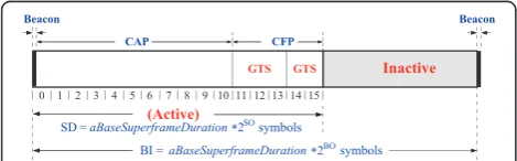
shown in Figure 1. Furthermore, the active portion of each superframe consists of three parts: beacon, CAP, and CFP, which is divided into 16 equal length slots. The length of one slot is equal to aBaseSlotDuration× 2SO symbols, whereaBaseSlotDurationis equal to 60 symbols.
In CAP, each node performs the CSMA/CA algorithm before transmitting data packet or control frame. Each node maintains three parameters: the number of back-offs (NB), contention window (CW), and backoff expo-nent (BE). The initial values of NB, CW, and BE are equal to 0, 2, and macMinBE, respectively, where mac-MinBEis equal to 3. In the located boundary of the next backoff period, a node takes delay for random backoff between 0 and 2BE-1 (2BEminus 1) unit backoff period (UBP), where UBP is equal to 20 symbols (or 80 bits). A node performs clear channel assessment (CCA) to make sure whether the channel is idle or busy, when the num-ber of random backoff periods is decreased to 0. The value of CW will be decreased by one if the channel is idle; and the second CCA will be performed if the value of CW is not equal to 0. If the value of CW is equal to 0, it means that the channel is idle after twice CCA; then a node is committed the data transmission. However, if the CCA is busy, the value of CW will be reset to 2; the value of NB is increased by 1; and the value of BE is in-creased by 1 up to the maximum BE (macMaxBE), where the valuemacMaxBEis equal to 5. The node will repeatedly take random delay if the value of NB is less than the value of macMaxCSMABackoff, where the value of macMaxCSMABackoff is equal to 4; and the transmission attempt fails if the value of NB is greater than the value ofmacMaxCSMABackoff.
On the other hand, to transmit packet in CFP, a node has to request the usage of GTS by sending GTS request packet to network coordinator in the CAP of the previ-ous superframe. The network coordinator allocates GTS to the device node if it successfully receives the request packet, then the device node transmits its packets by using the allocated GTS without contention.
3 The description of SUDAS
A star topology consists of one network coordinator and several device nodes, while the network coordinator periodically sends beacon frames to the device nodes. The network coordinator allocates the dedicated slots
for its device nodes, if it receives the requests for GTS packets in the CAP period, otherwise, the device nodes shall transmit their packets with contention in CAP. This article proposes a superframe duration adjustment scheme (SUDAS), to analyze both CAP and CFP for IEEE 802.15.4 MAC. SUDAS aims to accurately decide the values of GTS slot based on the length of packet size and packet arrival rate. SUDAS mainly improves the probability of success transmission, network goodput, average bandwidth utilization, and energy consumption by managing the GTS allocation for the requested device nodes. SUDAS can be expanded by considering the length of data packet, the SO value, and packet arrival rate. According to the IEEE 802.15.4 standard, let us de-note Tsd to be the time of SD as shown in Equation 1,
where aBaseSuperframeDuration and Rs are the
mini-mum duration of a superframe and data symbol rate with the values of 960 symbols and 62,500 symbol/s, re-spectively. Let us also denoteTslotas the time of one slot
duration, which can be obtained by Equation 2.
Tsd¼
aBaseSuperframeDuration 2SO
Rs ½in seconds
ð1Þ
Tslot ¼ Tsd
16 ½in seconds ð2Þ
Each device node with an allocated GTS ensures that the data transmission time, waiting time for ACK, time to transmit ACK packet, and interframe spacing (IFS) duration can be completed before the end of its GTS period. Let us denoteTfbe the time to transmit one data
packet and receive ACK packet, which can be obtained by Equation 3, whereTdata,TLack,Tack, andTLIFS are the
time to transmit data packet, time to waiting for ACK packet, time to transmit ACK packet, and time duration of IFS, respectively. The length ofLackis equal to 88 bits,
whereas the length ofLIFSis equal tomacMinLIFSPeriod
(160 bits) if the length of packet is greater than aMax-SIFSFrameSize (144 bits), otherwise, it is equal to mac-MinSIFSPeriod(48 bits).
according to its arrival rate by device n as shown in Equation 4, where λn and NGTS are the arrival rate of
data packets at devicenand the number of nodes to be allocated GTS slots in CFP, respectively.
T xn¼λn
TsdP
Rb ;
n ∈ ð1; NGTSÞ ð4Þ
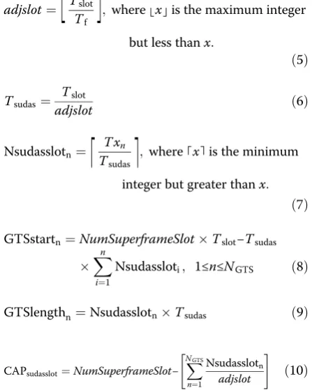
According to IEEE 802.15.4 standard, the maximum value to allocate the GTS slot duration is seven. Let us denote adjslotbe the integer value that will be used as the adjustment for the Tslot of IEEE 802.15.4 standard
become new smaller adjustment time of one slot dur-ation. The valueadjslotcan be calculated by Equation 5. Let us denoteTsudasbe the new time of one slot duration
in SUDAS, which can be calculated by Equation 6. Let us denote Nsudasslotn be the number of request slots
for each GTS of SUDAS by devicen, which is calculated by Equation 7. Let us denoteNumSuperframeSlotbe the number of slots in a superframe duration, which is equal to 16 according to IEEE 802.15.4 standard. Let us denote GTSstarn, and GTSlengthn as the starting time, and the
length of a GTS allocation for device n, which can be calculated by Equations 8 to 9, respectively. Let us also denote CAPsudasslot and CAPsudaslengthbe the number of
CAP slots and the time of CAP period based on SUDAS, which can be obtained by Equations 10 and 11, respect-ively, whereLbeacon is the length of beacon in bits while Tbeaconis the time interval of beacon.
adjslot¼
⌊
Tslot Tf⌋
;where⌊x⌋is the maximum integer
but less thanx:
ð5Þ
Tsudas¼ Tslot
adjslot ð6Þ
Nsudasslotn¼
⌈
T xn Tsudas⌉
;where⌈x⌉is the minimum
integer but greater thanx: ð7Þ
GTSstartn¼NumSuperframeSlotTslot−Tsudas Xn
i¼1
Nsudassloti; 1≤n≤NGTS ð8Þ
GTSlengthn¼NsudasslotnTsudas ð9Þ
CAPsudasslot¼NumSuperframeSlot− X NGTS
n¼1
Nsudasslotn
adjslot
" #
ð10Þ
CAPsudaslength ¼NumSuperframeSlot Tslot−Tbeacon − Tsudas NXGTS
n¼1
Nsudasslotn ð11Þ
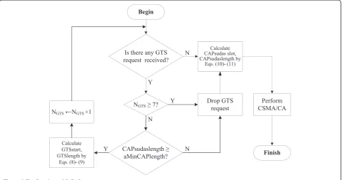
For more details about the aforementioned descrip-tion, we can explain SUDAS with flowchart as shown in Figure 2. We consider a star topology network having one network coordinator and several device nodes with the same value of six for SO and BO. By using Equation 5, we get the value ofadjslotto be 16. Based on the IEEE 802.15.4 standard, if each node sends to request one slot GTS in IEEE 802.15.4, and its request successfully re-ceived by network coordinator, thus the number of slots needed for CFP is seven as shown in Figure 3. In SUDAS, the number of slots needed for CFP is not more than one in the 15th slot. Furthermore, if there are more than seven device nodes in the star topology, the device nodes which are not allocated GTS can transmits their data packets more in CAP period because the CAP dur-ation of SUDAS (CAPsudaslength) is increased as shown in
Figure 4. By using SUDAS, the CFP period in super-frame duration effectively increases the average band-width utilization. On the other hand, the device nodes which are not getting GTS allocation can increase their data packets transmitted in CAP because the CAP dur-ation is increased.
4 Analysis of SUDAS
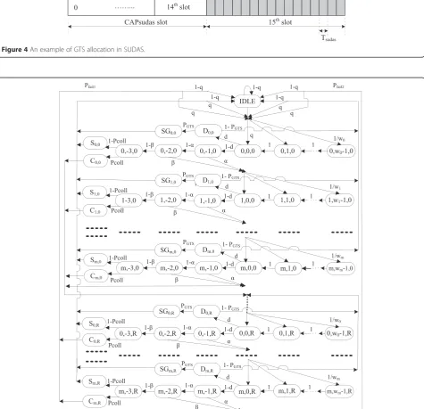
In this section, the proposed SUDAS based on the IEEE 802.15.4 MAC use slotted carrier sense multiple access with collision avoidance (CSMA/CA) for part of CAP and GTS transmission for part of CFP. This article also taking into account the case of acknowledged uplink data transmission investigated comprehensively via Markov chain model as shown in Figure 5. Letbi,j,kbe the stationary probability at
the stochastic state (s(t) =i,c(t) =j, andr(t) =k), wheres(t), c(t), and r(t) represent backoff stage, backoff counter, and number of retransmissions, respectively, shown as Equation 12, where bi,-1,k, bi,-2,k and bi,-3,k are the
sta-tionary probabilities for the first CCA (CCA1), the
second CCA (CCA2), and packet transmission,
respect-ively, at theith backoff stage and thekth retransmission. Let bSi,k and bCi,kbe the stationary probabilities of the
successful transmission and collision at the states ofSi,k
andCi,k as shown in Equations 13 and 14, respectively,
wheremandRare the maximum NB stage and retrans-missions, i.e., they are equal to 4 and 3, respectively. Let bSGi,kandbDi,kbe the stationary probabilities of the
stage and thekth retransmission as shown in Equations 15 and 16, respectively.
bi;j;k ¼tlim→∞P s tfð Þ ¼i; c tð Þ ¼j; r tð Þ ¼kg;for i∈ð0;mÞ;
j∈ −ð 3;wi−1Þ; k∈ð0;RÞ
ð12Þ
bSi;k¼ lim
t→∞P Ss tð Þ¼Si; r tð Þ ¼k
; i∈ð0; mÞ; k∈ð0; RÞ ð13Þ
bCi;k¼tlim→∞P Cs tð Þ¼Ci; r tð Þ ¼k
; i∈ð0; mÞ; k∈ð0; RÞ ð14Þ
bSGi;k¼t→lim∞P SGs tð Þ¼SGi; r tð Þ ¼k
; i∈ð0; mÞ; k∈ð0; RÞ ð15Þ
bDi;k¼ lim
t→∞P Ds tð Þ¼Di; r tð Þ ¼k
; i∈ð0; mÞ; k∈ð0; RÞ ð16Þ
Let us explain the parameters used in the Markov chain model as follows. Letwi¼2BEi be the backoff
win-dow at theith backoff stage of a device, where the back-off exponent BEi= 3, 4, 5, 5, and 5 for 0≤i≤m. An
IDLE state means that a device node has no packet to transmit. Let us denoteqbe the probability that a packet arrives at a node during the active period.
The MAC sublayer should transmit its packet if the remaining CSMA/CA steps, i.e., CCA analyses, the frame transmission, and any ACK can be completed be-fore the end of CAPsudaslength. Conversely, if the current
CAPsudaslength has not enough slots to transmit data
packets, it should defer transmission until the beginning of the CAPsudaslength in the next superframe duration.
Let d be the probability of defer transmission that no enough slot is left in the current CAPsudaslengthto
trans-mit data packet, which can be obtained by Equation 17, whereTtxCCAis the time to transmit CCA.
d ¼ 2TtxCCA þ Tf CAPsudaslength
ð17Þ
Let us denote α and βbe the probabilities that CCA1
and CCA2are busy, respectively. CCA1busy means that
the device node at one of the CCA1states while at least
one of the other nodes at packet transmission state, while CCA2busy means that the device node at one of
the CCA2states while at least one of the other nodes at
packet transmission state. Let us also denote Pcoll to be
the probability of the collision of packet transmission
Figure 2The flowchart of SUDAS.
Figure 4An example of GTS allocation in SUDAS.
after CCA2, i.e., the device node at packet transmission
state while at least one of the other nodes in the packet transmission state at the same time. Let us also denotePfail1
andPfail2to be the probabilities of fail transmission due to
the maximum number of retransmissions after collisions and no channel to use after reaching the maximum backoff stage at the maximum retransmission stage, respectively.
To analyze the Markov chain model, several state transi-tion probabilities are evaluated as shown from Equatransi-tions 18 to 26. Equation 18 states the probability that the back-off counter is decreased after each slot. Equation 19 gives the probability of finding busy channel either in CCA1
and CCA2. Equation 20 states the probability of picking a
backoff state in the next retransmission stage after the col-lision of packet transmission when having enough time to send packet in the remaining active period and channel idle in both CCA1and CCA2. Equation 21 states the
prob-ability of entering the IDLE state after the collision of packet transmission while reaching the maximum retrans-mission stage after finding the remaining active period to be enough to send packet and channel idle in both CCA1
and CCA2. Equation 22 states the probability that the
remaining CAP is not enough to send packet and need to defer and then pick the backoff state in the next super-frame. Equation 23 states the probability of successful packet transmission and picking new random backoff at the first backoff stage. Equation 24 states the probability of entering the IDLE state if the node has no data packet to transmit after successful packet transmission. Equation 25 states the probability of entering the IDLE state due to channel access failure. Equation 26 states the probability of going to the first backoff stage from the IDLE state if the node has data packet to transmit.
P ið;j;kji;jþ1;kÞ ¼1; i∈ð0;mÞ; j∈ð0; wi−2Þ; k∈ð0; RÞ
By using Equation 19, the stationary probabilitybi,j,kcan
be obtained by Equation 27. From Equation 20, b0,0,kcan
be obtained by Equation 28, whereYandXare the prob-abilities of entering the next backoff stage and the collision of packet transmission in a certain backoff stage, respect-ively. Similarly, bi,0,k can be obtained by Equation 29.
Fi-nally, the steady-state probabilities to perform random backoff (Prandb), CCA1 (PCCA1), CCA2 (PCCA2), packet
transmission (Ppt), successful packet transmission
(Psuc), collision of packet transmission (Pcopt), deferred
transmission (Pdtx), successful request for GTS packet
(Psg), and idle state (Pidle) can be obtained from
Equa-tions 30 to 38, respectively, wherePGTSis the
probabil-ity of requesting GTS allocation. Since the sum of probabilities in the Markov chain must be equal to one, we have Equation 39. By using Equations 30 to 39, we can get the value of b0,0,0 easily by using excel
where Y = (1−d)[a+ (1−a)b]; Z =Ym+ 1; U¼ 1−Z
Prandb=P(perform random backoff ):
¼Xm
PCCA1=P(perform the first clear channel assessment):
¼X
PCCA2=P(perform the second clear channel assessment):
¼X
Ppt=P(packet transmissions):
¼X
Psuc=P(successful packet transmissions):
¼X
Pcopt=P(collided packet transmissions):
¼Xm
Pdtx=P(deferred transmission):
¼Xm
Let ϕ1 and ϕ2be the conditional probabilities that a tagged node will be at one of the CCA1 states after
backoff and at one of the CCA2 states after sensing
channel idle in the CCA1, which can be obtained by
Equations 40 and 41, respectively. Let us denoteτbe the
probability that a device node can transmit a packet, i.e., the device node is in one of the CCA1 states and
senses the CCA2 is idle, while the other nodes are
not in the CCA1 state, which can be calculated by
Equation 42. Let us denote NGTS and NWGTS as the
number of nodes to be and not to be allocated GTS slots, respectively.
Sinceαis the probability of the CCA1busy, we can also
consider with the transmission of the data packets and GTS request packets. Let αdata and αrequest be the probabilities that CCA1is busy for sending data packets and GTS
re-quest packets, which can be obtained by Equations 43 and 44, respectively. Similarly, letβdataandβrequestbe the prob-abilities that CCA2 is busy for sending data packets and
GTS request packets, which can be obtained by Equations 45 and 46, respectively. Therefore,αandβcan be obtained by Equations 47 and 48, respectively. Finally, the previous mentioned probabilities of Pcoll, Pfail1, and Pfail2 can be
whereV0 ¼1−1−ðXðþXþZÞZRþÞ1−2XZandQ0 ¼1−ð12−Y2YÞRþ1þ4Y3þ4 Y4for simplicity.
τ ¼ φ1ð1−φ1Þ
Let denotePcr to be the probability of collision
trans-mission after j attempts (probability of packet being dropped due to collision retransmission), which can be calculated by Equation 52. Let PdropWGTS and PsucWGTS
Equations 53 and 54, respectively. Let us also denote
NWGTSrecvcoord and Tsim to be the number of
non-GTS packets received by the network coordinator and time of simulation, which can be calculated by Equation 55. Therefore, the goodput of SUDAS CAP in the network, denoted by SCAPsudaslength, can be calculated
by Equation 56.
Pcr ¼ XR
k¼1 Pcoll
ð Þk ð
52Þ
PdropWGTS ¼ PcrþPfail 1þPfail2 ð53Þ
PsucWGTS ¼ 1‐PdropWGTS ð54Þ
NWGTSrecvcoord ¼
1−P
ð Þ λnNWGTS 1−PdropWGTS
Tsim Ldata
ð55Þ
SCAPsudaslength ¼
NWGTSrecvcoordLdata Nbeacon BIcoord
ð56Þ
Let us denoteRreqandNreqto be the GTS request rate of
device node and the number of packets per request, respectively, then PGTS can be calculated by Equation
57. Let Ptsg be the probability of the successful GTS
transmission, which can be obtained by Equation 58, wherePsghas been done by Equation 37. Let also denote NGTSrecvcoord and SCFPsudaslength be the number of GTS
packets received by the network coordinator and the goodput of SUDAS CFP in the network, which can be calculated by Equations 59 and 60, respectively. Finally, the total goodput in the network, denoted byStotal, can be
calculated by Equation 61.
PGTS¼RreqNreq T xn
Tsd
ð57Þ
Ptsg¼Psg
PGTSþ1 Psg
ð1−dÞ ð58Þ
NGTSrecvcoord ¼
P λnNGTSPtsgTsim Ldata
ð59Þ
SCFPsudaslength¼
NGTSrecvcoordLdata NbeaconBIcoord
ð60Þ
Stotal ¼
NWGTSrecvcoord þNGTSrecvcoord
ð Þ Ldata
NbeaconBIcoord
ð61Þ
Let Nbeacon and Tq be the number of beacons and the
time to transmit one data packet and receive ACK packet in
CAPsudaslength, which can be obtained by Equations 62
and 63, respectively. Let us also denote bandwidth utilization (BU)CAPsudaslength, BUCFPsudaslength, and
BUsudastotal to be the BUs for CAP, CFP, and total
average amount in the network, which can be obtained by Equations 64 to 66, respectively.
Nbeacon¼ Tsim
Tsd
ð62Þ
Tq ¼2TtxCCAþTf ð63Þ
BUCAPsudaslength¼
NWGTSrecvcoordTq NbeaconCAPsudaslength
ð64Þ
BUCFPsudaslength¼
NGTSrecvcoordTf
Tsudas
X
NGTS
n¼1
Nsudasn
!
Nbeacon
ð65Þ
BUsudastotal¼
BUCAPsudaslengthþBUCFPsudaslength
2 ð66Þ
LetTeCAPsudaslengthandLdelaybe the estimated remaining
CAPsudaslength in time (seconds) and length (bits), which
can be calculated by Equations 67 to 68, respectively. Let us denoteEdev,Ecoord, andEtotalto be the energy consumptions
by device nodes, coordinator node, and total amount in the star topology, which can be calculated by Equations 69 to 71, respectively, where PWRidle, PWRtx, and
PWRrx are the power consumptions for idle,
transmit-ting a packet and receiving a packet, respectively; and LCCA, Lbeacon, and Lrequest are the transmission lengths
(bits) of CCA, beacon, and GTS request (72 bits), respectively. Let us denote Dnode to be the distance
between a device node and its coordinator.
TeCAPsudaslength¼PdtxCAPsudaslength¼b0;0;0 V U
d CAPsudaslength
ð67Þ
ECoord ¼ PWRidlePidleSDCoord Tsim BICoord
þ PWRtx Lbeacon
Rb
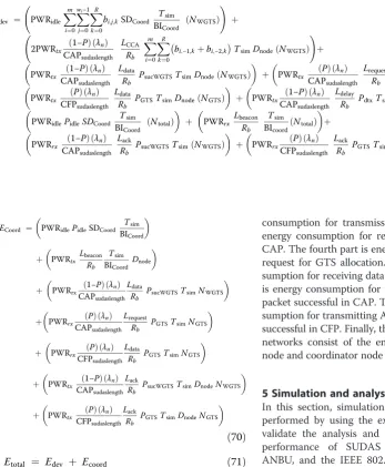
The energy consumption of device node consists of ten parts as shown in Equation 69. The first part is en-ergy consumption for backoff. The second part is enen-ergy consumption for CCA transmission. The third part is energy consumption for data packet transmission using CSMA/CA in CAP. The fourth part is energy tion for request GTS. The fifth part is energy consump-tion for data packet transmission using GTS in CFP. The sixth part is energy consumption for waiting due to deferred transmission. The seventh part is energy con-sumption for idle. The eighth part is energy consump-tion for receiving beacon. The ninth part is energy consumption for receiving ACK if transmitting packet is successful, and the tenth part is energy consumption for ACK if transmission packet using GTS is successful.
The energy consumption of coordinator node consists of seven parts as shown in Equation 70. The first part is energy consumption for idle. The second part is energy
consumption for transmission beacon. The third part is energy consumption for receiving data at CSMA/CA in CAP. The fourth part is energy consumption for receiving request for GTS allocation. The fifth part is energy con-sumption for receiving data at GTS in CFP. The sixth part is energy consumption for transmitting ACK, if receiving packet successful in CAP. The seventh part is energy con-sumption for transmitting ACK, if receiving packet GTS is successful in CFP. Finally, the total energy consumption in networks consist of the energy consumption by devices node and coordinator node as shown in Equation 71.
5 Simulation and analysis results
In this section, simulation experiments for SUDAS are performed by using the extended Castalia simulator to validate the analysis and performance evaluation. The performance of SUDAS is compared with NGAS, ANBU, and the IEEE 802.15.4 standard, which include the analytical (ana) and simulation (sim) results. We consider a star topology with one PAN coordinator and 20 device nodes, whereDnodeis equal to 10 m. To
simu-late the performance of power consumption, we con-sider the radio parameters of Chipcon’s CC2420 2.4 GHz for the IEEE 802.15.4 RF transceiver [32], where the transmitting power PWRtx, the receiving power
PWRrx, and the idle power PWRidleare 31.32mW, 35.28
mW, and 712μW, respectively [33]. The BO and SO set-tings follow the IEEE 802.15.4 standard and the pro-posed SUDAS algorithm, which are fixed to be six. We compute the probability of successful packet transmis-sion in CAP, network goodput, average bandwidth utilization (BU), and total network energy consumption, where traffic load varies from 0.1 to 1(full loaded). Table 1 summarizes the simulation parameters.
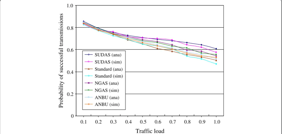
Figure 6 shows the probability of successful transmis-sion arriving at the PAN coordinator against the traffic load by analytical and simulation. In CFP, nodes do not Edev ¼ PWRidle
compete with each other and each node has the dedi-cated slots, hence we only consider part of CAP in this article. The proposed SUDAS algorithm has higher probability of successful transmissions than those of NGAS, ANBU, and IEEE 802.15.4 standard because the length of CAPsudaslengthis longer than those of CAPNGAS,
CAPANBU, and CAPstandard, respectively.
Figure 7 shows the network goodput against traffic load. The network goodput obtained by simulation is very close to that obtained by the analytical model. It is obvious the network goodput of SUDAS is higher than those of the other algorithms. In the light traffic load (i.e., traffic load is equal to 0.1 and 0.2), the network
goodput of SUDAS is almost the same as those of NGAS, ANBU, and IEEE standard; however, SUDAS outperforms the other algorithms as the traffic load increases. The average goodput of SUDAS increases by 8.30%, 14.23%, and 19.21% compared to NGAS, ANBU, and IEEE 802.15.4 standard, respectively.
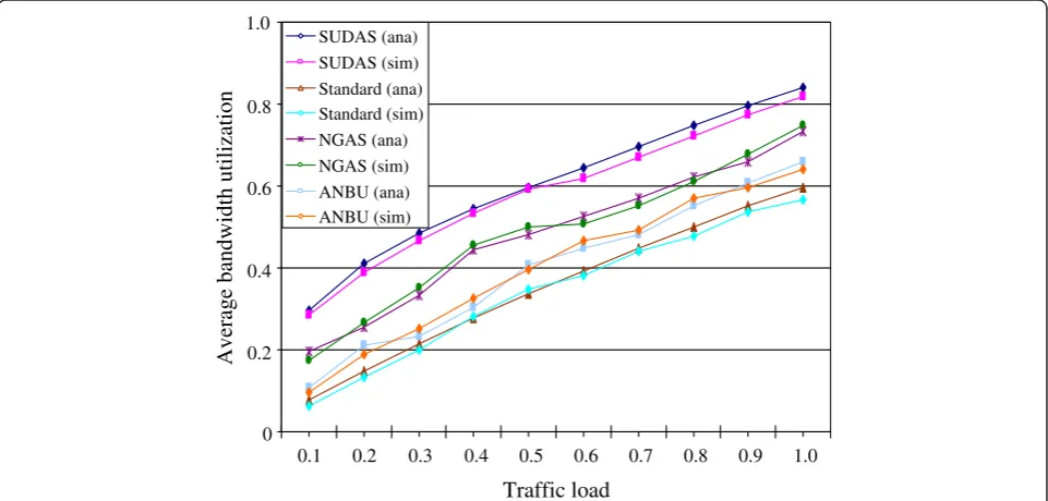
Figure 8 shows the average BU against traffic load. The average bandwidth utilization of SUDAS has better efficiency than those of other algorithms. The average bandwidth utilization of SUDAS increases by 20.41%, 33.80%, and 41.65% compared to NGAS, ANBU, and IEEE 802.15.4 standard, respectively. SUDAS can improve the average bandwidth utilization because the size of slot is adjustable with the data packet to be transmitted, i.e., SUDAS can reduce the waste of bandwidth.
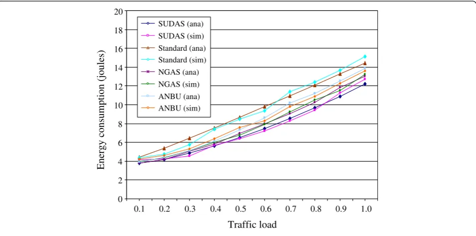
Figure 9 shows the network energy consumption against traffic load. The average energy consumption of SUDAS reduces by 5.65%, 12.94%, and 26.15% compared to NGAS, ANBU, and IEEE standard, respectively. SUDAS consumes lesser network energy than those of other algorithms, because CAPsudaslength is longer than
those of other algorithms. Moreover, SUDAS has greater probability of successful transmission than those of other algorithms, especially in heavy traffic load, which means that SUDAS minimizes the energy consumption when retransmitting data packet. The energy consump-tion is obtained by summing the energy consumpconsump-tion of PAN coordinator and all of device nodes in the network.
6 Conclusions
In this article, SUDAS is proposed to improve the IEEE 802.15.4 medium access control, which analyzes not only Table 1 The simulation parameters
Parameter Value
Physical data rate 250 kbps
Packet length (Ldata) 560 bits
UBP 80 bits
NumSuperframeSlots 16
MacPacketOverhead 112 bits
ACK length (Lack) 88 bits
Dnode 10 m
PWRtx 31.32 mW
PWRrx 35.28 mW
PWRidle 712μW
BO = SO 6
BEmin 3
BEmax 5
SUDAS (ana)
SUDAS (sim) Standard (ana) Standard (sim) NGAS (ana) NGAS (sim)
ANBU (ana) ANBU (sim)
Probability
of
successful
transmissions
0 0.2 0.4 0.6 0.8 1.0
0.1 0.2 0.3 0.4 0.5 0.6 0.7 0.8 0.9 1.0
Traffic load
CAP but also CFP. SUDAS performs with the adjust-able length of the slot in the superframe duration based on the length of data packet, so that it can ac-curately decide for the starting time, and the GTS length to be allocated for the requested devices to al-leviate the waste of GTS bandwidth utilization. SUDAS is expected to effectively allocate GTS to the requested devices, because the length of CAPsudaslength
is longer than those of other algorithms.
This paper also presented a comprehensive Markov chain analysis of IEEE 802.15.4, specifically for star topology, to predict the probability of successful transmission, the network goodput, average bandwidth utilization, as well as the network energy consumption. The validity of the analytical model is shown by closely matching its predictions of the simulation results. The analytical model and simulation experiment results show that the performance of SUDAS is better than those of other
Network
goodput
(kbps)
0 20 40 60 80 100 120
0.1 0.2 0.3 0.4 0.5 0.6 0.7 0.8 0.9 1.0
Traffic load SUDAS (ana)
SUDAS (sim) Standard (ana) Standard (sim) NGAS (ana)
NGAS (sim) ANBU (ana) ANBU (sim)
Figure 7The network goodput against traffic load.
Average
bandwidth
utilization
0 0.2 0.4 0.6 0.8 1.0
0.1 0.2 0.3 0.4 0.5 0.6 0.7 0.8 0.9 1.0
Traffic load SUDAS (ana)
SUDAS (sim) Standard (ana) Standard (sim) NGAS (ana) NGAS (sim) ANBU (ana) ANBU (sim)
algorithms in terms of the probability of successful trans-mission, network goodput, average bandwidth utilization, and energy consumption.
6.1 Summary of parameters
aBaseSlotDuration, the minimum Number of symbols in a slot;aBaseSuperframeDuration, the minimum Number of symbols in an active period; aMinCAPlength, the minimum value of CAP length; aNumSuperframeSlots, number of superframe slots; macMaxBE, the maximum value of backoff exponent; macMaxCSMABackoff, the maximum value of Number of backoffs;macMinBE, the minimum value of backoff exponent.
6.2 Summary of symbols
adjslot, the integer value that will be used as the adjust-ment become new smaller adjustadjust-ment time of one slot duration; bCi,k, stationary probability of the collision at
the states of Ci,k; bDi,k, stationary probability of waiting
due to deferred transmission at state of Di,k; bi,−1,k,
stationary probability for CCA1 at the stochastic state
(s(t) =i and r(t) =k); bi,−2,k, stationary probability for
CCA2 at the stochastic state (s(t) =i and r(t) =k); bi,−3,k,
stationary probability for packet transmission at the stochastic state (s(t) =iandr(t) =k);bi,j,k, stationary
prob-ability at the stochastic state (s(t) = i, c(t) = j and r(t) = k); BIcoord, beacon interval of coordinator; BOcoord, beacon
order for coordinator; bSGi,k, stationary probability of
successful request GTS allocation at state of SGi,k; bSi,k,
stationary probability of the successful transmission at the states ofSi,k; BUCAPsudaslength, the bandwidth utilization for
CAPsudaslength; BUCFPsudaslength, the bandwidth utilization
for CFPsudaslength; BUsudastotal, the total average bandwidth
utilization in the network; c(t), backoff counter in sto-chastic state; CAPANBU, the time of CAP period in
ANBU; CAPNGAS, the time of CAP period in NGAS;
CAPsudaslength, the time of CAP period in SUDAS;
CAPsudasslot, number of CAP slots in SUDAS;d, the
prob-ability of defer transmission that no enough slot is left in the current CAPsudaslength to transmit data frame;Dnode,
the distance between device nodes and its coordinator; Ecoord, energy consumption by coordinator node; Edev,
energy consumption by device nodes; Etotal, total energy
consumption of the network; GTSlengthn, the length of
GTS allocation for devicen; GTSstartn, the starting time of
GTS allocation for devicen; IDLE, state that a device node has no packet to transmit;Lack, the lengths of ACK is 88 in
bits;Lbeacon, the length of beacon is 760 in bits;LCCA, the
lengths of CCA is 32 in bits; Ldata, the length of data
packet is 560 in bits; Ldelay, the length of the
esti-mated remaining CAPsudaslength in bits; Lrequest, the
length of GTS request is 72 in bits; m, the maximum number of backoff stage (4);Nbeacon, number of beacons; NGTS, number of nodes need to be allocated GTS slot; NGTSrecvcoord, number of GTS packets received by
coord-inator;Nreq, number of packets per request; Nsudasslotn,
number of request slots for each GTS of SUDAS by device n; Ntotal, total Number of nodes in the network;NWGTS,
number of nodes do not need to be allocated GTS slot;
NWGTSrecvcoord, number of non GTS packets received by
coordinator; P, probability that a node generates time critical packets; PCCA1, steady-state probability for
CCA1; PCCA2, steady-state probability for CCA2; Pcoll,
probability of packet collision in a certain backoff
Energy
consumption
(joules)
0 2 4 6 8 10 12 14 16 18 20
0.1 0.2 0.3 0.4 0.5 0.6 0.7 0.8 0.9 1.0
Traffic load SUDAS (ana)
SUDAS (sim) Standard (ana) Standard (sim) NGAS (ana)
NGAS (sim) ANBU (ana) ANBU (sim)
stage; Pcopt, steady-state probability for the collided
packet transmission; Pcr, probability of a packet being
dropped due to collision retransmission; PdropWGTS,
probability of non GTS packet dropped as transmitting from device node to its coordinator; Pdtx, steady-state
probability for waiting time due to defer transmission; Pfail1, probability of fail transmission due to the maximum
number of retransmissions after collisions;Pfail2, probability
of fail transmission due to no channel to use after reaching the maximum backoff stage at the maximum retransmis-sion stage; PGTS, probability of request GTS allocation; Pidle, steady-state probability for idle; Ppt, steady-state
probability for the packet transmission;Pranb, steady-state
probability to perform random backoff; PSG, steady-state
probability for successful request GTS packet; Psuc,
steady-state probability for the successful packet transmis-sion; PsucWGTS, probability of successful transmission for
non GTS packet as transmitting from device node to its coordinator;Ptsg, probability of successful GTS
transmis-sion; PWRidle, the power consumption for idle; PWRrx,
the power consumption for receiving a packet; PWRtx, the
power consumption for transmitting a packet; R, the maximum number of retransmissions (3); r(t), number of retransmissions in stochastic state; Rb, data rate
(250 kbps); Rreq, GTS request rate of device node; Rs,
symbol rate (62,500 symbols/sec); s(t), backoff stage in stochastic state; SCAPsudaslength, the goodput of
CAPsudaslength which is a part of CAP in the network;
SCFPsudaslength, the goodput of CFPsudaslength which is a
part of CFP in the network; SDcoord, superframe duration
of coordinator; SOcoord, superframe order for coordinator; Stotal, total goodput of the star network;Tack, time to wait
for ACK packet; Tbeacon, time interval of beacon; Tdata,
time to transmit data packet; TeCAPsudaslength, the
esti-mated remaining of CAP SUDAS length in time;Tf, time
of transmit one data packet and receive ACK packet; TLack, time to transmit ACK packet; TLIFS, time of IFS
duration;Tq, time to transmit one packet data and receive
ACK packet in CAP SUDAS length; Tsd, time of
superframe duration; Tsim, time of simulation; Tslot,
time of one slot duration; Tsudas, new time of one slot
duration in SUDAS; TtxCCA, time to transmit CCA; Txn, time to transmit data packet according to its arrival
rate for device n; wi, backoff window; X, probability of
collision of packet transmission in a certain backoff stage; Y, probability of entering the next backoff stage; α, prob-ability that CCA1is busy; αdata, probability that CCA1 is
busy due to data packet;αrequest, probability that CCA1 is busy due to request GTS packet;β, probability that CCA2
is busy; βdata, probability that CCA2 is busy due to data
packet; βrequest, probability that CCA2 is busy due to
request GTS packet; λn, arrival rate of data packet for
device n;τ, probability that a tagged node can transmit a packet;ϕ1, conditional probability that a tagged node will
be at one of the CCA1states after backoff;ϕ2, conditional
probability that a tagged node will be at one of the CCA2
states after sensing channel idle in the CCA1.
Abbreviations
ACK:acknowledgement; ANBU: a new GTS allocation scheme with bandwidth utilization; BE: backoff exponent; BI: beacon interval; BO: beacon order; CAP: contention access period; CCA: clear channel assessment; CFP: contention free period; CSMA/CA: carrier sense multiple access with collision avoidance; CW: contention window; GTS: guaranteed time slot; IEEE: Institute of Electrical and Electronics Engineers; IFS: interframe spacing; LIFS: long interframe spacing; LR-WPAN: low-rate wireless personal area network; MAC: medium access control sublayer; NB: number of backoffs; NGAS: a new GTS allocation scheme; PAN: personal area network; PHY: physical layer; SD: superframe duration (in symbols); SIFS: short interframe spacing; SO: superframe order; SUDAS: superframe duration adjustment scheme; UBP: unit backoff period (80 bits).
Competing interests
The authors declare that they have no competing interests.
Acknowledgements
This study was supported in part by the Ministry of Science and Technology (MOST) of Taiwan under Grant No. MOST 99-2221-E-011-119.
Author details
1National Taiwan University of Science and Technology, 43, Keelung Rd,
Section 4, Taipei 106, Taiwan.2Ling Tung University, 1, Ling Tung Rd, Taichung 408, Taiwan.3Politeknik Elektronika Negeri Surabaya, Kampus ITS
Sukolilo, Surabaya 60111, Indonesia.
Received: 11 December 2014 Accepted: 12 February 2015
References
1. IEEE 802.15.4, part 15.4: wireless medium access control (MAC) and physical layer (PHY) specifications for low-rate wireless personal area networks (WPANs), IEEE standard for information technology. September 2006 2. AN Alvi, SS Naqvi, SH Bouk, N Javaid, U Qasim, ZA Khan,Evaluation of
slotted CSMA/CA of IEEE 802.15.4(Seventh International Conference on Broadband, Wireless Computing, Communication and Applications, Canada, 2012)
3. K Ashrafuzzaman, K Sup Kwak, On the performance analysis of the contention access period of IEEE 802.15.4 MAC. IEEE Commun Lett
15, 9 (2011)
4. T-R Park, T-H Kim, J-Y Choi, S Choi, W-H Kwon, Throughput and energy consumption analysis of IEEE 802.15.4 slotted CSMA/CA. IEEE. Electron Lett
41(18), 1017–1019 (2005)
5. TJ Lee, HR Lee, MY Chung, MAC throughput limit analysis of slotted CSMA/CA in IEEE 802.15.4 WPAN. IEEE Commun Lett10(7), 561–563 (2006) 6. S Pollin, M Ergen, S Ergen, B Bougard, L Der Perre, I Moerman, A Bahai, P
Varaiya, F Catthoor, Performance analysis of slotted carrier sense IEEE 802.15.4 medium access layer. IEEE T Wirel Commun7(9), 3359–3371 (2008) 7. Y Zhang, F Shu,Packet Size Optimization for Goodput and Energy Efficiency
Enhancement in Slotted IEEE 802.15.4 Networks. IEEE Wireless Communications and Networking Conference, 2009, pp. 1–6
8. J He, Z Tang, HH Chen, Q Zhang, An accurate and scalable analytical model for IEEE 802.15.4 slotted CSMA/CA networks. IEEE T Wirel Commun
8(1), 440–448 (2009)
9. Z Xiao, C He, L Jiang, An analytical model for IEEE 802.15.4 with sleep mode based on time-varying queue, inIEEE International Conference on Communications (ICC), Kyoto, Japan, 2011
10. C Buratti, Performance analysis of IEEE 802.15.4 beacon-enabled mode. IEEE Trans. Veh. Technol59, 2031–2045 (2010)
11. Z Tao, S Panwar, D Gu, J Zhang, Performance analysis and a proposed improvement for the IEEE 802.15.4 contention access period. IEEE WCNC
4, 1811–1818 (2006)
13. YK Huang, AC Pang, HN Hung, A comprehensive analysis of low-power operation for beacon-enabled IEEE 802.15.4 wireless networks. IEEE T Wirel Commun8(11), 5601–5611 (2009)
14. M Khanafer, M Guennoun, HT Mouftah, Adaptive Sleeping Periods in IEEE 802.15.4 for Efficient Energy Savings: Markov-based Theoretical Analysis, in IEEE International Conference on Communications (ICC), Kyoto, Japan, 2011 15. B Gao, C He, L Jiang,Modeling and Analysis of IEEE 802.15.4 CSMA/CA with Sleep Mode Enabled. International Conference on Communication Systems, pp.6-11, Guangzhou, China, 2008
16. C-Y Jung, H-Y Hwang, D-K Sung, G-U Hwang, Enhanced Markov chain model and throughput analysis of the slotted CSMA/CA for IEEE 802.15.4 under unsaturated traffic conditions. IEEE T Veh Technol58(1), 473–478 (2009) 17. B Shrestha, E Hossain, S Camorlinga, A Markov model for IEEE 802.15.4 MAC
with GTS transmissions and heterogeneous traffic in non-saturation mode, inIEEE International Conference on Communication Systems (ICCS), pp. 56–61, Singapore, 2010
18. B-H Lee, M Udin Harun Al Rasyid, H-K Wu,Analysis of Superframe Adjustment and Beacon Transmission for IEEE 802.15.4 Cluster Tree Networks. EURASIP Journal on Wireless Communication and Networking, July 2012 19. M Martalo, S Busanelli, G Ferrari, Markov Chain-based performance analysis of
multihop IEEE 802.15.4 wireless networks. Perform Evaluation66, 722–741 (2009) 20. P Park, C Fischione, K Johansson, Performance analysis of GTS allocation in
beacon enabled IEEE 802.15.4, in6thAnnual IEEE Communications Society Conference on Sensor, Mesh and Ad Hoc Communications and Networks, 2009, pp. 1–9
21. A Koubaa, M Alves, E Tovar, GTS allocation analysis in IEEE 802.15.4 for real-time wireless sensor networks. Paper presented at the 20th International Parallel and Distributed Processing Symposium, IEEE, Rhodes Island, 25–29 April 2006 22. S-T Sheu, YY Shih, WT Lee, CSMA/CF Protocol for IEEE 802.15.4 WPANs.
IEEE Trans. Veh. Technol.58(3), 1501–1516 (2009)
23. L-C Ko, Z-T Chou,A Novel Multi-Beacon Superframe Structure with Greedy GTS Allocation for IEEE 802.15.4 Wireless PANs. IEEE Wireless Communications and Networking Conference (WCNC), pp.2328-2333, Kowloon, March, 2007. 24. A Koubaa, M Alves, E Tovar, A Cunha, An implicit GTS allocation mechanism
in IEEE 802.15.4 for time-sensitive wireless sensor networks: theory and practice. Springer Real-Time Systems39, 169–204 (2008)
25. H-W Cho, S-J Bae, M-Y Chung,Utilization-aware dynamic GTS allocation scheme in IEEE 802.15.4. 010 16th Asia-Pacific Conference on Communications (APCC), 2010, pp. 210–214
26. Y-K Huang, A-C Pang, H-N Hung, An adaptive GTS allocation scheme for IEEE 802.15.4. IEEE T Parall Distr19(5), 641–651 (2008)
27. L Cheng, AG Bourgeois, X Zhang,A new GTS allocation scheme for IEEE 802.15.4 networks with improved bandwidth utilization. Communications and Information Technologies, 2007. ISCIT '07. International Symposium, 2007, pp. 1143–1148
28. B Shrestha, E Hossain, S Camorlinga, R Krishnamoorthy, D Niyato,An Optimization-Based GTS Allocation Scheme for IEEE 802.15.4 MAC with Application to Wireless Body-Area Sensor Networks. 2010 IEEE International Conference on Communications (ICC), 2010, pp. 1–6
29. L Yang, S Zeng,A New GTS Allocation Schemes for IEEE 802.15.4. 2012 5th International Conference on BioMedical Engineering and Informatics, 2012, pp. 1398–1401
30. YS Seo, DY Kim, J Cho, A dynamic CFP allocation and opportunity contention-based WBAN MAC protocol. IEEE T Wirel Commun
E93.B(4), 850–853 (2010)
31. H-K Wu, B-H Lee, M Udin Harun Al Rasyid,Study on Superframe Adjustment for Cluster Tree in Wireless Sensor Networks. Proceedings of the 2012 IEEE International Conference on Cyber Technology in Automation, Control and Intelligent Systems, 2012, pp. 43–47
32. AS Chipcon SmartRF® CC2420 datasheet (rev 1.2), Chipcon corp., 2004. 33. B Bougard, F Catthoor, DC Daly, A Chandrakasan, W Dehaene,Energy
Efficiency of the IEEE 802.15.4 Standard in Dense Wireless Microsensor Networks: Modeling and Improvement Perspectives. Proceeding of Design, Automation and Test in Europe Conference and Exhibition. (DATE’05), pp.196-201, Mar. 2005.
Submit your manuscript to a
journal and benefi t from:
7 Convenient online submission
7 Rigorous peer review
7 Immediate publication on acceptance
7 Open access: articles freely available online
7 High visibility within the fi eld
7 Retaining the copyright to your article