Two-phase cooling system with controlled
pulsations
Karapet Eloyan1,*
, Alexey Kreta1,2
and Egor Tkachenko1,2
1
Kutateladze Institute of Thermophysics SB RAS, 630090, Novosibirsk, Russia 2
Novosibirsk State University, 630090, Novosibirsk, Russia
Abstract. One of the promising ways of removing large heat fluxes from the surface of heat-stressed elements of electronic devices is the use of evaporating thin layer of liquid film, moving under the action of the gas flow in a flat channel. In this work, a prototype of evaporative cooling system for high heat flux removal with forced circulation of liquid and gas coolants with controlled pulsation, capable to remove heat flux of up to 1,5 kW/cm2 and higher was presented. For the first time the regime with controlled pulsation is used. Due to pulsations, it is possible to achieve high values of critical heat flux due to a brief increase in the flow rate of the liquid, which allows to "wash off" large dry spots and prevent the occurrence of zones of flow and drying.
1 Introduction
One of the major problems in the field of applied thermal physics is creation of an effective cooling system for microelectronics, power chips, «green» IT. Modern cooling systems for processors are able to remove up to 150-200 W/cm2. Development of more effective and compact cooling system for electronics will lead to rapid development of powerful microelectronics. Today, in DATA centers, about 30-40% of all energy is used by cooling system. Currently, the global industry is ready to produce high-performance electronic components where the heat flux density at individual sites can reach 1000 W/cm2 and higher [1]. However, the introduction and use of these devices faces challenges of removing such high specific heat fluxes into the ambient medium.
One of the promising ways of removing large heat fluxes from the surface of heat-stressed elements of electronic devices is the use of two-phase flows in microchannels [2,3]. The most efficient flow regimes in the channel (in terms of heat removal) are annular or stratified flow [1]. Authors of [4-6] suggested to use artificially formed stratified flow in the channel, namely a thin liquid film, moving under the action of the gas flow in the channel. Recent experimental investigations conducted in works [7-9] proved possible removal of heat fluxes with density of up to 1200 W/cm2 from the heating area of 10x10 mm2 using this method. The works [10,11] showed that such a system can operate stably in
*
a wide range of the channel heights (0.17-2.00 mm) and angles of the channel inclination to the horizon (0-360°). In [12] heat transfer in a liquid film shear-driven in a channel with an extended heater has been studied (under comparatively low heat fluxes).
One of the effective modifications of a two-phase flow (thin liquid film moving under the action of a gas flow) is the addition of controlled pulsations to the system. The works [13-16] describe the effect of pulsations on heat transfer in a two-phase system. The effect of pulsations on heat transfer and critical heat flux for a two-phase system with R134a is shown in [17]. Pulsations in some cases (a short period of pulsations) led to an increase in heat transfer by more than 20%, while for long periods of pulsations the heat exchange deteriorates.
Using previous studies on a two-phase system and modifications of the working setup, it was possible to create a new prototype cooling system with controlled pulsation. The work presents the data of the first experiments.
2 Experimental setup
A schematic diagram of the new experimental prototype of evaporative cooling system with controlled pulsation is shown in Fig. 1. The system has three closed working circuits: two liquid circuits and a gas circuit. The first liquid circuit, as seen from Fig. 1, contains pump Grundfos DDE 15-4 (LP) for pumping working liquid with constant flow. The second liquid circuit contains membrane pump Etatron BT MA/AD (MP) for pumping working liquid with pulsations. The gas circuit contains a membrane vacuum pump-compressor MVNK 3x4 (CG), which produces an output of up to 400 l/min of working gas. To control gas flow rate, the Bronkhorst F-111AC-70K flow controller (CV) is used, which has an operating gas flow range from 0 to 100 l/min. At the exit from the test section, the vapor-gas mixture condenses in the plate heat exchanger ACH16-14H-F (C). After condensation, the gas and liquid enter the separator (S), from which they again begin to circulate in the prototype of the cooling system (TS). The test liquid is ultrapure water created with the Merck Millipore Direct-Q 3 UV water purification system.
Fig. 1. Schematic diagram (left) and photograph (right) of the experimental prototype of evaporative cooling system: TS – testing section; C – condenser; S – separator; R – receiver; CV – control valve; LP – liquid pump; CG – gas vacuum pump-compressor; BWS – building water supply, MP – membrane pump.
The lower part of the copper rod is wound with an isolated nichrome tape with a known resistance (not shown in Fig. 2). In the process of passing an electric current through the nichrome tape, the generated Joule heat creates a heat flux inside the copper rod. The power supply AC-DC 3300W SM 100-AR-75 DLT LPF is used. The heated copper rod is covered with thermal insulation material 5 mm thick (not shown in Fig. 2).
3 Experimental results
The first experiments on heat transfer with controlled pulsation were carried out. The average flow rate remained constant during the experiment (150 ml/min, Re = 233), while the gas flow rate varied from 20 l/min to 30 l/min (superficial gas velocity varied from 33 m/s to 50 m/s). The flow rate at the pulsation pump varied from 0 to 70 ml/min. The volume of one pulsation is 2.8 ml. Changing the period of pulsation changes the flow rate of liquid. The flow rate at the pump without pulsations varied from 80 to 150 ml/min. The heat exchange crisis was fixed by thermocouples built into the heater. The uncontrolled and sharp rise in temperature served as a sign that the crisis had come. The critical heat flux was determined by electrical power of the source divided by cross section area.
qcr = U I/S (1)
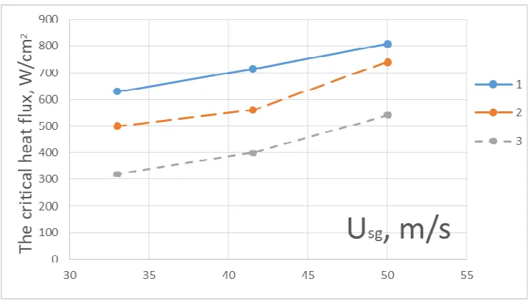
As can be seen from Figure 3, heat flux in a two-phase system with pulsations is lower than that without pulsation. This is due to the period of pulsation. In this experiment, it is large and intervals without pulsation lead to the fact that there is a crisis and the pulsation does not have time to reach the heater. At the same time, it is evident that even with a decrease in the period of pulsations, heat flux decreases. This phenomenon is also associated with a large period of pulsations. Since the proportion of pulsations increases, the constant part of the fluid flow decreases, so the crisis occurs at lower heat fluxes. The data are in good agreement with [17].
Figure 3. The dependence of the critical heat flux on the gas velocity with and without pulsations (the average flow rate of liquid is 150 ml/min). 1 – without pulsation, 2 – the flow rate of pulsation part is 30 ml/min, 3 – the flow rate of pulsation part is 70 ml/min. The temperature of the liquid at the inlet is 25 ° C.
kW/cm2 was dissipated, which is 20% more than with a constant flow of liquid. At a flow rate of 300 ml/min, the flow regime is no longer stratified, but changes into an annular flow. The maximum pressure drop in the experiment did not exceed 0.3 bar.
4 Conclusions
The prototype of the cooling system was modified by a liquid circuit, which makes it possible to create and control pulsations in a two-phase system. The first experiments showed that pulsations with large periods reduce heat exchange. Deterioration of heat exchange leads to the fact that the crisis occurs at lower heat fluxes. While pulsations with small periods allow an increase in heat transfer by 20%. It is shown that the effect of pulsations on heat transfer can be positive and negative, depending on the period of pulsations. The influence of other parameters (the size of pulsations, the shape of pulsations) and the flow regime on the heat transfer of the system require further study.
The reported study was funded by RFBR according to the research project № 18-38-00683.
References
1. A. Bar-Cohen, C. Holloway, Journal of Physics: Conference Series, 745, 022002 (2016)
2. Zhang W., Hibiki T., Mishima K., Mi Y., International Journal of Heat and Mass Transfer, 49, p. 1058, (2006)
3. Mudawar I., Qu W. International Journal of Heat and Mass Transfer, 47, p. 2045, (2004)
4. O.A. Kabov, Yu.V. Lyulin, I.V. Marchuk, D.V. Zaitsev, International Journal of Heat and Fluid Flow, 28, 103 (2007)
5. O.A. Kabov, D.V. Zaitsev, Multiphase Science and Technology, 21, 249-266 (2009) 6. O.A. Kabov, D.V. Zaitsev, V.V. Cheverda, A. Bar-Cohen, Experimental Thermal and
Fluid Science, 35, 825 (2011)
7. E.M. Tkachenko, D.V. Zaitsev, E.V. Orlik, O.A. Kabov, Journal of Physics: Conference Series, 754, 032019 (2016)
8. D. Zaitsev, E. Tkachenko, E. Orlik, O. Kabov, MATEC Web of Conferences, 92, 01037 (2016)
9. D. Zaitsev, E. Tkachenko, O. Kabov, EPJ Web of Conferences, 159, 00054 (2017).
10. D. Zaitsev, O. Kabov, MATEC Web of Conferences, 84, 00043 (2016)
11. E.M. Tkachenko, D.V. Zaitsev, MATEC Web of Conferences, 72, 01114 (2016)
12. T. Hirokawa, H. Ohta and O. Kabov, Interfacial Phenomena and Heat Transfer, 3, 303
(2015)
13. H. Tuo, P. Hrnjak, International Journal of Refrigeration, 36, 1263–1275 (2013). 14. H. Tuo, P. Hrnjak, International Journal of Heat and Mass Transfer, 71, 639–652
(2014).
16. J. Li, P. Hrnjak, International Journal of Refrigeration, 85, 144–156 (2018).