K.Pandiyan,
1Dr. Ashesh Tiwari
2Final Year ME Student, Department of Design & Thermal Engineering, Department of Mechanical Engineering,
Institute of Engineering and Technology, Devi Ahilya Vishwavidyalaya, Indore, M.P, India1
Professor & Head, Department of Mechanical Engineering, Institute of Engineering and Technology, Devi Ahilya
Vishwavidyalaya, Indore, M.P, India2
ABSTRACT: The crankshaft is one of the most critically loaded components as it experiences cyclic loads in the form of bending and torsion during its service life. Its failure will cause serious damage to the engine so it’s important at the time of design to verify fatigue strength and torsional vibration and physical validation on test bed as well as on field vehicles. More challenges in crankshaft design due to increasing vehicle payloads, lower weight requirement, higher efficiency and longer durability life. This paper will give an overall guideline for the student and industry engineers for designing the crankshaft which can serve the longer durability life without any failures.
KEYWORDS: Fatigue strength, Transient analysis and Damper
I. INTRODUCTION
A crankshaft is part of an engine four-bar mechanism that rotates as the piston moves up and down. The first bar is the connecting rod, the second bar is the crankshaft from the crank pin to the main journal, the third bar is the engine block, and the fourth bar is the piston. The crankshaft turns around and the upper end of the connecting rod oscillates up/down while the lower end rotates with the crankshaft. The purpose of the four-bar mechanism is to convert the up and down motion of the piston into the rotating motion of the crankshaft.
A rod journal, or crank pin, is the area of the crankshaft that the connecting rod attaches to. The surface is highly polished because it makes up part of the bearing system.
A main journal is the area of the crankshaft that attaches to the block. The main journal cooperatively makes up the rotating axis of the crankshaft. The surface is highly polished because it also makes up part of the bearing system. Arms serve as a connection between a main and rod journal or a rod journal to rod journal connection.
Counterweights are attached to the arm and serve as counter balance mass to counteract the unbalance forces created by the rod journals, arms, connecting rod and the piston assembly.
A crankshaft bay includes all elements of the crankshaft between two adjacent main journals.
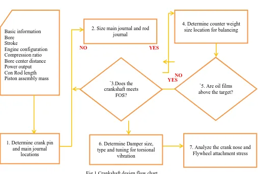
II. CRANKSHAFTDESIGNPROCEDURE
Fig 1 Crankshaft design flow chart
III. CRANKSHAFTDESIGN CONSIDERATIONS AND PROPOSITIONAL DIMENSIONS
The present design consideration is to increase the stiffness of the crankshaft and reduce its overall length by incorporating narrow journals of large diameter. For the required wall thickness and coolant passages, the minimum cylinder centers can be around 1.2 times the cylinder bore diameter for an engine having its stroke equal to nearly the bore. The maximum diameter of the big-end for the connecting-rod assembly that can pass throughthe cylinder is 0.65 times
of the bore. The proportions of the crankshaft are as follows: Cylinder bore diameter = D
Cylinder Centre distance = 1.20 D Big-end journals diameter = 0.65 D Main-end journal diameter = 0.75 D Big-end journal width = 0.35 D Main-end journal width = 0.40 D Web thickness = 0.25 D
Fillet radius of journal and webs = 0.04 D
To increase the fatigue life of the shaft, the fillet radius between journals and webs should be as large as possible but not less than 5% of the journal diameter. The overlap between the diameters of the big-end crankpin and the main-end journal depends on the length of the stroke i.e. the crank-throw. A long-stroke engine has very little overlap, requiring thicker web sections, and a short-stroke engine has considerable overlap which strengthens the shaft.
6. Determine Damper size, type and tuning for torsional
vibration
NO YES
YES Basic information Bore Stroke Engine configuration Compression ratio Bore center distance Power output Con Rod length Piston assembly mass
1. Determine crank pin and main journal
locations
2. Size main journal and rod journal
4. Determine counter weight size location for balancing
`3.Does the crankshaft meets
FOS?
`5. Are oil films above the target?
bending and 15% in torsion. Crankshaft journals are ground to provide a surface finish better than 0.5 urn, to minimize bearing wear.
Crankshafts normally have either integral or attachable counterweights. These counterweights counteract the centrifugal force created by each individual crankpin and its webs as the whole crankshaft is rotated about the main-journal axis. In absence of the counterweights, the crankpin masses tend to bend and distort the crankshaft causing excessive edge-loading in the main bearings. Therefore, each half crank-web is generally extended in the opposite direction to that of the crankpin, to counterbalance the effects of the crankpin.
IV.CRANKSHAFT MATERIALS
Crankshafts materials should be readily shaped, machined and heat-treated, and have adequate strength, toughness, hardness, and high fatigue strength. The crankshaft is manufactured from steel either by forging or casting. The main bearing and connecting rod bearing liners are made of Babbitt, a tin and lead alloy. Forged crankshafts are stronger than the cast crankshafts, but are more expensive. Forged crankshafts are made from 38MnS6 or similar type steel. Forging makes a very dense, tough shaft with a grain running parallel to the principal stress direction.
Crankshaft failure modes
A crankshaft consists of several parts such as the crank-web, crank-pins and journals and therefore there could be a fault with either of these parts. There could be various modes of a crankshaft during service. The failure could be due to crack developed in any section such as the web, pin or journal and the piece could get completely broken in the worst case. Also there could be a case of slip shrinks which would be problematic.
Apart from that there could be web failure due to fatigue which is due to the presence of deflections which are beyond permissible limits and hence cause bending of the crankshaft causing fractures due to fatigue.
There are other defects which might develop in the crankshaft but are not directly related to the forces on it and such defects include corrosion, scoring and ovality of the cross-section of the crankshaft
Reasons for failure of crankshaft
Fatigue Failure: Majority of steel crankshaft failure occurs because of fatigue failure, which may originate at the
change of cross-section such as at the lip of oil hole bored in the crankpin.
Failure due to Vibration: If the engine is running with heavy vibration especially torsional vibration, it may lead to
crack in the crankpin and journal.
Insufficient lubrication: If the lubrication of bearing in the crankshaft is starved, it may lead to wipe out of the bearing
and failure of the crankshaft
Over Pressurized Cylinder: It may happen that there is hydraulic lock (water leakage) inside the liner and due to
extreme pressure the crankshaft may slip or even bent (if safety valve of that unit is not working).
Cracks: Cracks can develop at the fillet between the journal and the web, particularly between the position
corresponding to 10 o’clock and 2 o’clock when the piston is at T.D.C.
Examples of crankshaft failures:
Fig 2 Different fatigue failures
V. VERIFICATION AND VALIDATION METHODS
Fatigue strength of crankshaft against working load is very important to avoid the durability failures. This can be evaluated by different verification methods using finite element analysis. Single throw FEA is the first step to find the stress and fatigue factor of safety.
Fig 3 FEA analysis
In addition to finite element analysis physical validation is also required to confirm the crankshaft life. The physical validation method require prototype crankshaft. Sometime whole crankshaft manufacturing is an expensive one also without good confidence no point in investing for the whole crankshaft. Single throw for one cylinder can be manufacture first and the same can be validated on the test rig of life estimation and to finalize on fillet radius, crank pin diameter, main journal diameter and overlap between pin and main journal.
Fig 4 Fatigue life estimation test rig
Transient analysis is the method for the crankshaft dynamic analysis. In the dynamic analysis one complete cycle load is applied on crankshaft with respect to the firing order sequence. This provides the stresses very close the working condition stress level. For doing the same complete crank train assembly is taken into account along with damper and flywheel assembly. Meshing is done through hyper mesh and solver is the Nastran. The expected result will be as below.
Fig 5 Transient analysis
To select the suitable damper torsional vibration on the engine is to be known. This is possible by measuring the torsional vibration at different orders. Acceptable limit is taken based on the experience in the range of 0.14 to 0.2 degrees. In case measured values are exceeded then the suitable damper selected through different test to control the torsional vibration with in the acceptable limit
.
Fig 6 Damper to control torsional vibration
VI.RESULTS AND OBSERVATIONS
Crankshaft stresses are within the fatigue limit for 160 bar peak firing pressure. The fatigue strength of the material is 286 MPa. Forged steel material 38MnS6 is the material suitable for the high cylinder pressure conditions. To control torsional vibration, noise and overall engine vibration damper is required for the crankshaft at front end.
Classical method calculation:
Crank pin fillet stress is 232.6 MPa. Stress values are higher due to the fact reaction point is considered center of the main journals.
Static FEA results:
Crank pin fillet stress is 118.9 MPa.
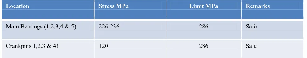
Tansient analysis stress results
Location Stress MPa Limit MPa Remarks
Main Bearings (1,2,3,4 & 5) 226-236 286 Safe
Crankpins 1,2,3 & 4) 120 286 Safe
VII. CONCLUSIONS
• Hand calculation is the first step to verify the crankshaft strength. Stress levels are within the fatigue limit for the
bending load.
Dampers are controlling torsional vibration and due to this engine overall vibration level reduced. In turn engine over all vibration reduction helped to reduce the noise.
• Crankshaft with 38MnS6 material is safe for 160 bar peak cylinder pressure operation without any failure in both
bending and torsion.
REFERENCES
1. S.M. H-Gangaraj , Politecnico di Milano “Failure Analysis of a Four Cylinder Diesel Engine Crankshaft Made From Nodular Cast Iron” The Journal of Engine Research/Vol. 22 / Spring 2011
2. Farzin H. Montazersadgh and Ali Fatemi “Stress Analysis and Optimization of Crankshafts Subject to Dynamic Loading” The University of Toledo Augest 2007.
3. D.S.Patil, NBN Sinhgad “Design & Analysis of Crankshaft Bending Test Rig for Actual Engine Condition” 1st International and 16th National Conference on Machines and Mechanisms (iNaCoMM2013), IIT Roorkee, India, Dec 18-20 2013
4. Alex K D, Arjun P, Hassan K &Vyshak P ”FEA approach to dynamic analysis of Crankshaft” Proceedings of the National Conference on Emerging Trends In Mechanical Engineering 2013
5. Sanjay B , V M Nandedkar, Surender Kumar Kaundal “Finite Element Analysis Approach for Stress Analysis of Crankshaft under Dynamic Loading” International journal of Science & engineering research, Volume-4, Issue-2, February-2013, ISSN 2229-5518 6. Morita T, T Suna Y, and Okada A“Influence of Dynamic Damper Pulley Design on Engine Front Noise," SAE Technical Paper
2001-01-1419, 2001, doi: 10.4271/2001-01-1419
7. JianMeng, Yongqi Liu, Ruixiang Liu “Finite Element Analysis of 4-Cylinder Diesel Crankshaft”I.J. Image, Graphics and Signal Processing, 2011, 5, 22-29 Published Online August 2011 in MECS
8. Troy Feese, P.E.and Charles Hill“Guidelines for preventing torsional vibration problems in reciprocating machinery” Engineering Dynamics Incorporated, 16117 University Oak, San Antonio, Texas 78249, (210) 492-9100, October 7, 2002