Downlink Capacity Improvement for LTE
Using Multi-Cell MIMO during Handover
Megha.B1, Lalitha.Y.S2
P.G. Student, Department of Electronics Engineering, AIET College, Kalaburagi, Karnataka, India1
P.G H.O.D, Department of Electronics Engineering, AIET College, Kalaburagi, Karnataka, India2
ABSTRACT: In today’s world the high data speed mobile users areincreasing day by day in 4G-LTE networks, as
number of mobile user increases we need to serve all the mobile users with the same Quality of Service (QoS) and data rate in all region of the cell coverage area. In this project, the Variable Step Size Griffiths (VSSG) Algorithm is implemented which is responsible for steering the radiation pattern of the eNodeB with Multiple Input Multiple output (MIMO)antenna’s from -90 degree to +90 degree. After steering the main beam, the detection is performed using MUSIC algorithm which detects the UE’s located at cell boundaries during handover to provide better signal strength to meet the standards QoS of 4G-LTE. The radiation pattern is analysed for the various cases like, Less Antenna Elements & Single Jammer, Less Antenna Elements and Multiple Jammers, More Antenna Elements and Single Jammer and finally More Antenna Elements and Multiple Jammers.VSSG will have the lowest Mean square error convergence as compared to Leaky Least Mean Square Algorithm (LLMS), and Griffiths Algorithm. Finally the Capacity of Single input single output (SISO) and Multiple Input Multiple output (MIMO) are also compared and proved that the 4G-LTE (using MIMO-VSSG) has the better capacity as compared to other algorithms.
KEYWORDS:LTE-Handover, UE, MUSIC, RLS, LLMS, Griffiths, VSSG
I. INTRODUCTION
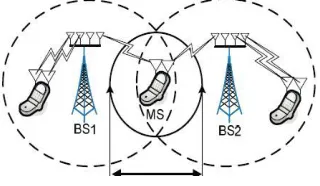
According to the considerable growth of mobile users and high data rate service patterns 4G-LTE expects high data rate services even in handover region. In the latest wireless systems, multiple-input multiple output (MIMO) has been used to improve capacity and reliability through the use of spatial diversity or multiplexing transmission.MIMO (multiple-input - multiple output) systems are those that have multiple antenna elements at both transmitter and receiver [1].They were first investigated by computer simulations in the 1980s, and later papers explored them analytically.For single-cell (SC) MIMO adaptation, many previous works have been presented to achieve the capacity gain through the adoption of statistical beam forming, on ergodic link capacity. However, SC MIMO schemes have limits to the capacity gain for cell edge users. There have been several papers on multi-cell (MC) MIMO transmission which have focused on reducing interference at the cell edge using smart scheduling and adaptation strategies However, the previous MC MIMO methods are inappropriate for handover users because those are based on fast BS Cooperation. Thus, here we propose a Variable step size Griffith’s algorithms transmission power beam for UE’s that exploits the better QoS in boundaries of cell where the signal power is less [2].
Vol. 4, Issue 5, May 2015
The paper is categorized as, Section (II) MUSIC algorithm for detection of UE at cell boundary regions Section (III)
Implementation of different Beam forming Transmission Algorithms-RLS, LLMS, Griffiths and VSSG. Section (IV)
Capacity computation.
II. RELATED WORK
MULTIPLESIGNALCLASSIFICATION(MUSIC)
The MUSIC algorithm assures to provide unbiased estimates of the number of signals, the angles of arrival and the strengths of the waveforms. Here it is assumed that the noise correlation matrix is diagonal. The incident signals may be correlated creating a non diagonal signal correlation matrix. Because MUSIC exploits the noise Eigen vector subspace, it is sometimes referred to as a subspace method.
The MUSIC pseudo spectrum is given by
)
(
)
(
1
a
E
E
a
P
MUSIC
H N NHWhere,
a
(
)
is steering vector for an angle
andE
N is L x L-M matrix comprising of noise Eigen vectors.III. BEAMFORMINGTRANSMISSIONALGORITHMS
The beam forming algorithms are used to form the main beam towards the detected UE and nulls or reduced beam towards the interference users [4]. The algorithms for beam forming are – Recursive Least Square (RLS) Algorithm, Leaky Least Mean Square (LLMS) Algorithm, Griffiths Algorithm and Variable Step Size Griffiths Algorithm.
A. Recursive Least Square Algorithm
The Recursive least square (RLS) is an algorithm which finds recursively the filter coefficients that minimize a weighted linear least squares cost function relating to the input signals. The autocorrelation matrix for RLS algorithm is given by
)
1
(
'
)
1
(
X
X
R
xx
Where, X is induced signal, X’ is the transpose of X. The weight vector is given by the equation
w (n+1) = w (n) + [ɘ(s(n)-X’ w(n+1))]
B. Leaky Least Mean Square Algorithm
The Eigen value decomposition of autocorrelation matrix
R
xx sometimes produces zero Eigen values, then LMS adaptive filter has more than one modes that are not driven or un-damped. Since it is possible for the un-damped modes to become unstable, it is important to stabilize the LMS by forcing these modes to zero. One way to accomplish this is to introduce leakage coefficient
into auto correlation matrix, step size and weight vector equation.The autocorrelation matrix for Leaky LMS algorithm is given by
XX
I
E
R
xx
H
Where, X’ is induced signal, XH is Hermitian transpose of X,
is Leaky Coefficient which takes any value in the range0
1
, I is LxL identity matrix and L is number of antenna elements.The weight vector is given by the equation
) ( ) ( ] 1 [ ) ( ) 1
(n w n n e* n x n
w
C. Griffiths Algorithm
Griffiths algorithm makes use of certain priori knowledge (when available) to create an effective real time adaptation process. The algorithm can be used for a number of applications including Noise Control, Adaptive Beam-forming and Acoustic Signal Processing. The cross correlation
R
sx between the desired signal d(n) and induced signal x(n) is given by
s S nsx
d
n
x
n
R
1)
(
)
(
Where,‘d(n)’ is desired signal samples, Ss is number of samples and x(n) is induced signal samples.
The weight update equation for Griffiths algorithm can be derived by using LMS algorithm, which is given by
)
(
)
(
2
2
)
(
)
1
(
n
w
n
r
y
n
x
n
w
sx
Where,
is the step size,r
sx is the cross- correlation andy
(
n
)
is the array output.D. Variable Step Size Griffiths Algorithm
The motivation behind this algorithm is to get faster convergence through the use of a variable step size LMS algorithm and a smoother gradient through the use of the Griffiths’ algorithm. It was also observed that the algorithm performed better with the normalization of gradient. Normalization of the gradient led to a significant drop in the gradient noise. The step size is calculated by including the constants
and
The parameter
decides how correlated each step size value is when compared with the previous step size value and parameter
decides the measure of increase or decrease in the step size to be made in accordance with the rise or fall in the prediction error.The weight update equation for VSSG algorithm is given by
x
l
+
w(n)
=
1)
+
W(n
IV. CAPACITY COMPUTATION
Before computing the capacity for MIMO systems, first we need to compute the Singular Value decomposition of the Channel Co-efficient.
A = B * D * CT Where,
B is an m × k matrix, C is an n × k matrix.
D is a k × k matrix, k is the rank of the matrix A.
For SISO,
Vol. 4, Issue 5, May 2015
For MIMO,
_ = 2(1 + ∗ ) ÷
V. EXPERIMENTAL RESULTS
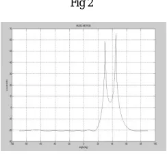
Figure 2 shows the output of MUSIC method, two users are detected at 30 and 45degrees
Fig 2
Figure 3 RLS algorithm, the number of antenna elements=8, desired angle=45, number of jammers=1, 1 Jamming direction=10
Fig 3
Figure 4 LLMS Algorithm, the number of antenna elements=8, desired angle=30, number of jammers=2, 1 Jamming direction=10, 2 Jamming direction=20
Figure 5 Griffiths Algorithm (a) the number of antenna elements=100, desired angle=45, number of jammers=1, 1 Jamming direction=10. (b) MSE v/s Angle.
Fig 5(a) Fig 5(b)
Figure 6 VSSG Algorithm (a) the number of antenna elements=100, desired angle=45, number of jammers=2, 1 Jamming direction=10, 2 Jamming direction=20. (b) Step size variation (c) MSE v/s Angle.
Fig 6(a) Fig 6(b) Fig 6(c)
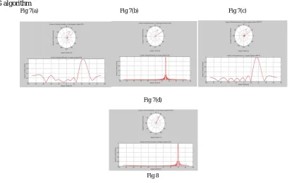
Figure 7 Handover with respect to target eNodeB (a) RLS algorithm (b) LLMS algorithm (c) Griffiths algorithm (d) VSSG algorithm
Fig 7(a) Fig 7(b) Fig 7(c)
Fig 7(d)
Vol. 4, Issue 5, May 2015
Figure 8 Capacity computations for SISO and MIMO
VI. CONCLUSION
It has been shown that the proposed VSSG algorithm is more efficient for 4G- LTE cell boundary users, where the transmission signal strength from eNodeB is less to provide the better QoS with less path loss and interference. Therefore, one can avoid the number iterations and time delay required to converge the Mean square error to zero during the UE’s handover between source eNodeB to target eNodeB, with respect to different beam steering algorithms , so that high data service users will maintain the required QoS for the data services without much packet loss. Using the proposed algorithm with more number of transmitting and receiving antenna (MIMO), the better Quality of service can be provided without any degradation for handover region users
REFERENCES
[1] D. Tomecki, S. Stanczak, and M. Kaliszan, “Joint optimization of transmit and receivebeam-formers in a multicast MIMO system with power control,” in Proc. IEEE WirelessCommunications and Networking Conference (WCNC), Budapest, Hungary, April, 5–8
2009.
[2] H.V.Kumaraswamy, "Implementation of Variable step size Griffiths' algorithm for Adaptive Beam forming", in the IEEE- International symposium on Microwaves-2008(ISM-08), in ISM- 08 Bangalore, ISM-08 Pages 91-95.Cheng-Chung Lin, Kumbesan Sandrasegaran , Scott Reeves , “Handover algorithm with joint processing in LTE-advanced”, IEEE ECTI-CON, pp 1-4,May 2012.
[3] Y. Zhong and X. Chen, “MUSIC imaging and electromagnetic inverse scattering of multiply scattering small anisotropic spheres,” IEEETrans. Antennas Prop, vol. 55, no. 12, pp. 3542–3549, 2007.