Transactions of the 17th International Conference on Structural Mechanics in Reactor Technology (SMiRT 17)
Prague, Czech Republic, August 17 –22, 2003
Paper # K09-4
Research on 3-D Base Isolation System Applied to New Power Reactor 3-D Seismic
Isolation Device with Rolling Seal Type Air Spring : Part 1
Junji Suhara1), Tadashi Tamura1), Kazuya Ohta1), Yasuo Okada1), Satoshi MORO2)
1)
Energy Engineering Division, Shimizu Corporation, Japan
2)
The Japan Atomic Power Company, Japan
ABSTRACT
Three dimensional (3D) seismic isolation device has been developed to use for the base isolation system of the heavy building like a nuclear reactor building. The developed device is the 3D seismic isolation device that consists of the laminated rubber bearing as a horizontal isolation device and the rolling seal type air spring as the vertical isolation device in series.
In this research, the 3D seismic isolation device reduction model whose scale is 1/10 is made and the workability of the device by the horizontal and vertical dynamic load is examined. Two experiment parameters are considered. One is the case that the structure of the part that the horizontal load and the vertical load contact is pin condition and the other is the case of the roller condition. As a result of the examination, the workability of the vertical direction is confirmed when the horizontal load acts.
The pressure resistant ability test for the air spring is performed by the monotonic pressurization. As the result, it is confirmed that pressure resistant ability improved by restricting the side deformation of the air spring and that the material of the existing air spring can withstand high pressure use sufficiently.
As the result, it is confirmed that the developed 3D seismic isolation device is applicable to the actual plant.
KEY WORDS: seismic isolation, 3-dimensional, air spring, rolling seal, rubber bearing, FBR.
INTRODUCTION
The 3D seismic isolation device has been developed to use for the base isolation system of the heavy building like a nuclear reactor building. The 3D seismic isolation device consists of the laminated rubber bearing as a horizontal isolation device and the rolling seal type air spring as the vertical isolation device in series.
As the laminated rubber bearing and air spring are practically and widely used in ordinary buildings and industrial structures, reliability of these devices is demonstrated.
Each device has no problem in using separately, but in case of connecting two devices in series, there are two problems. One is workability of the vertical direction when the horizontal load acts. The other is high supporting ability for the economical efficiency and simplicity of arrangement.
In this study, feasibility test is carried out to verify the applicability of the proposed 3D isolation device to the actual structure.
ACTUAL 3D SEISMIC ISOLATION DEVICE
Outline of proposed 3D seismic isolation device is shown in Fig. 1 and dynamic properties and specifications of device are shown in Table 1. The dynamic properties are determined by considering the results of horizontal and vertical earthquake response analysis [1].
Table 1 Outline of 3D Device
Horizontal Initial Period 1.0 s Horizontal Isolation Period 2.8 s Horizontal Yield Coefficient 0.1 Vertical Isolation Period 2.0 s Dynamic
Properties
Vertical Damping Factor 0.2 Supporting Load 9800 kN Diameter of RB (m) 1.6 m Total rubber thickness of RB 0.225 m Diameter of Air Compartment 3.0 m Height of Air Compartment 1.4 m Specifications
Pressure of Air Compartment 1.6 MPa
Fig. 1 3Dimensional isolation device k u
Stopper (Damper)
Air supply
Diameter D Normal
condition Defor-mation condition
Steel liner Lower basemat
Cylinder Contact part
Upper basemat
Laminated rubber bearing
Toatmo -sphe
Air compartment Height
The device realizes the 3D isolation property by the laminated rubber bearing as the horizontal isolation system and the air spring as the vertical isolation system independently. The specifications of laminated rubber bearing are decided by the past horizontal isolation study on FBR plant [2].
The air compartment is set up in lower basemat. The vertical working part consists of the rolling seal type air spring that can work in large deformation. The surrounding air spring system consists of air supply, air tanks and leveling devices that keep the height of structure constant automatically.
The product of the pressure by the effective contact area decides the supporting capacity of the air spring. The maximum static pressure of ordinary air springs is about 0.9MPa. The pressure of the proposed device is supposed about 1.6MPa at normal condition and about 2.0MPa at earthquake. So the supporting Load of a device is 9800 kN, the arrangement of the devices is expected to become simple. The example of the arrangement to the FBR plant is shown in Fig. 2.
It is necessary for the contact part that transmit the horizontal force to have almost no friction because of smooth move in vertical direction.
9300 4600 8500 7000 1 3500 2 7000 3 8300
4 5 6
10500 80300 5300 7 8 8500 11 8900 9 10 3500 12 A 89 00 81 00 B D1 94 00 10 50 0 E1 G1 81 00 89 00 K L 60 00 A 89 00 B C D 55 00 25 00 45 00 E 53 90 0 F 60 00 25 00 J G H 45 00 46 00 K L 89 00 6a 10500 5 8a 30300 2500 30 00 31 10 0
‹ ó‹ C‚ ΂ Ë i175ŚÂ j
3D isolation device
Fig. 2 Arrangement of device
FEASIBILITY TEST
1) Objectives of test
The objectives of this test are shown below.
a) Confirmation of workability of vertical direction under horizontal load b) Grasp of ultimate pressure of ordinary air spring
2) Similarity Law
The scale ratio of the model to a prototype is 1/10 and both acceleration and stress are equal to those of a prototype. The similarity law is shown in Table 2.
Table 2 Similarity Law
Parameter Similitude λ=10
Length 1/λ 1/10
Velocity 1/√λ 1/3.16
Acceleration 1 1
Time 1/√λ 1/3.16
Mass 1/λ2
1/100 Stress 1 1
3) Test Model
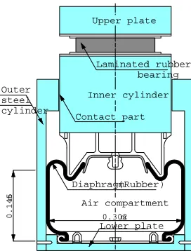
The pressure of test model is lower than the specification of the actual device because the existing air spring is used in test model. The dimension of the test model is calculated by the modified prototype whose pressure of the air compartment is 0.8MPa. The dimension of the test model is shown in Table 3 comparing with the prototype. The outline of test model is shown in Fig. 3.
Table 3 Dimension of Modified Prototype and Test Model
Parameter Prototype Model
Support Load (kN) 4900 49
Horizontal Isolation Period (s) 2.8 0.886 Vertical Isolation Period (s) 2.0 0.633 Pressure of Air Compartment (MPa) 0.8 0.8 Diameter of Air Compartment (m) 3.02 0.302 Height of Air Compartment (m) 1.45 0.145
Diameter of RB (m) 1.6 0.16
Total rubber thickness of RB (m) 0.45 0.045
Fig. 3 3D isolation device for experiment (scale : 1/10)
4) Test Case
Test cases are shown in Fig. 4. a) Case 1: Ultimate static test
To grasp the ultimate pressure value and failure mode of existing air spring, the monotonic pressurization test are performed under constant height of air spring. In this test, water is used instead of air.
The dynamic vertical tests are performed for reference to grasp the vertical dynamic property of this test model. Outline of this test is shown in Photo 1.
b) Case 2: Dynamic vertical test
The dynamic vertical tests under sinusoidal wave force are performed to grasp the vertical dynamic properties and to grasp the effect of contact conditions, that is effect to the vertical properties by the difference of pin and roller condition.
c) Case 3: Dynamic vertical test with constant horizontal force
The vertical dynamic tests with constant horizontal force are performed to grasp the vertical dynamic properties and to grasp the effect of contact conditions.
d) Case 4: Dynamic vertical and horizontal test
The dynamic tests acting the vertical and horizontal force simultaneously are performed to grasp the vertical dynamic properties and to grasp the effect of contact conditions.
Outline of test 2-4 is shown in Photo 2.
Fig. 4 Test case Outer
steel cylinder
0.145
m
0.302m
Laminated rubber bearing
Inner cylinder Upper plate
Lower plate Contact part
Diaphragm (Rubber)
Air compartment
(1)Ultimate static test
Water
Water pressure (Gradual increase)
Contact cond
(2)Dynamic vertical test
Sinusoidal wave forceEPin ERoller
Inner cylinder Piston
All directions are fixed
Horizontal force (Constant)
(3)Dynamic vertical test with constant zontal force
(4)Dynamic vertical and horizontal
Sinusoidal wave force
Laminated rubber bearing
Photo 1 View of Test Case 1 Photo 2 View of Test Case 2-4
5) Test Results
a) Case 1: Ultimate static test
As the results of ultimate pressurization test, the maximum pressure was more than 7.5MPa. The ultimate static pressure of ordinary air springs is about 2.0MPa, but the pressure resistant ability improved by restricting the side deformation of the air spring
The failure is occurred at the piston made of aluminum as shown in Photo 3. After broken pieces of the piston penetrated the rubber seal, a leakage of water is occurred.
b) Case 2: Dynamic vertical test
The relations between the vertical force and the vertical displacement under the sinusoidal vertical force (amplitude: 20mm, frequency: 1Hz, 1.5Hz, 2Hz) are shown in Fig. 5.
It is recognized from these figures that the effect of the force frequency is almost small and the restoring property shows nonlinear property without hysteresis.
c) Case 3: Dynamic vertical test with constant horizontal force
The relations between the vertical force and the vertical displacement under the sinusoidal vertical force (amplitude: 20mm, frequency: 1.5Hz) and constant horizontal force (horizontal displacement: 20mm) are shown in Fig. 6,7, comparing the effect of contact conditions. Fig.6 shows the result of pin condition and Fig.7 shows the result of roller condition.
It is recognized from these figures that the effect of the contact condition is almost small and the restoring property shows nonlinear property with slight hysteresis. It seems that there was a little friction on the contact part, but the device worked smoothly at the test.
d) Case 4: Dynamic vertical and horizontal test
The vertical and horizontal property under the sinusoidal vertical force (amplitude: 20mm, frequency: 1.0Hz, 1.5Hz) and the sinusoidal horizontal force (amplitude: 20mm, frequency: 1.0Hz, load: 5.9kN) are shown in Fig. 8. These figures show the results of pin condition on the contact part.
It is recognized from these figures that the effect of the forcing frequency is almost small and the vertical restoring property is almost the same as the results of the dynamic vertical test shown in Fig.5.
As the horizontal restoring property is almost the same as the device test results of the laminated rubber bearing, it is recognized that the effect of the contact part is almost small.
The vertical and horizontal property under the sinusoidal vertical force (amplitude: 20mm, frequency: 1.5Hz) and the sinusoidal horizontal force (amplitude: 20mm, 40mm, frequency: 1.0Hz, load: 5.9kN, 12kN) are shown in Fig. 9. These figures show the results of roller condition on the contact part.
50 60
- 20
40
20 Ver t i cal Di sp. ( mm) Ver t i cal
Load ( kN)
Fig.5 Dynam ic vertical property under cyclic load ( Vertical amplitude : 2cm, Pin type )
50 60
- 20
40
20 Ver t i cal Di sp. ( mm) Ver t i cal
Load ( kN)
50 60
- 20
40
20 Ver t i cal Di sp. ( mm) Ver t i cal
Load ( kN)
50 60
- 20
40
20 Ver t i cal Di sp. ( mm) Ver t i cal
Load ( kN)
50 60
- 20
40
20 Ver t i cal Di sp. ( mm) Ver t i cal
Load ( kN)
50 60
- 20
40
20 Ver t i cal Di sp. ( mm) Ver t i cal
Load ( kN)
50 60
- 20
40
20 Ver t i cal Di sp. ( mm) Ver t i cal
Load ( kN)
Vertical frequency : 1Hz Vertical frequency : 1.5Hz Vertical frequency : 2Hz
Fig. 6 Dynam ic vertical property with consta nt horizontal displacement ( Constant Horizontal Disp. : 2cm,Pin type )
Vertical ampl itude : 2cm Vertical frequency : 1Hz
Vertical ampl itude : 2cm Vertical frequency : 1.5Hz
Fig. 7 Dynamic vertical property with constant horizontal displacement ( Constant Horizontal Disp. : 2cm,Roller type )
Vertical ampl itude : 2cm Vertical frequency : 1Hz
Vertical ampl itude : 2cm Vertical frequency : 1.5Hz
50 60
- 20
40
20 Ver t i cal Di sp. ( mm) Ver t i cal
Load ( kN) Hor i zont alLoad ( kN)
Hor i zont al Di sp. ( mm) 20
- 10
- 20 0 10
- 20 20
- 60 - 40 40 60
Fig. 9 Dynamic vertical and horizontal property ( Vertical amplitude:2cm,Vertical frequency:1.5Hz,Roller type )
Hori zontal amplit ude : 2cm,Horizont al frequency : 1Hz
50 60
- 20
40
20 Ver t i cal Di sp. ( mm) Ver t i cal
Load ( kN) Hor i zont alLoad ( kN)
Hor i zont al Di sp. ( mm) 20
- 10
- 20 0 10
- 20 20
- 60 - 40 40 60
Hori zontal amplit ude : 4cm,Horizont al frequency : 1Hz Vertical ampl itude : 2cm ,Vertical frequency : 1Hz
50 60
- 20
40
20 Ver t i cal Di sp. ( mm) Ver t i cal
Load ( kN) Hor i zont alLoad ( kN)
Hor i zont al Di sp. ( mm) 20
- 10
- 20 0 10
- 20 20
- 60 - 40 40 60
50 60
- 20
40
20 Ver t i cal Di sp. ( mm) Ver t i cal
Load ( kN) Hor i zont alLoad ( kN)
Hor i zont al Di sp. ( mm) 20
- 10
- 20 0 10
- 20 20
- 60 - 40 40 60
Fig. 8 Dynam ic vertical and horizontal property ( Horiz ontal amplitude:2cm,Horizonta l frequency:1Hz, Pin type )
Photo 3 Damage of Air Spring Piston
CONCLUSION
The 3D seismic isolation device reduction model whose scale is 1/10 is made and the workability of the device by the horizontal and vertical dynamic load is confirmed.
The pressure resistant ability test for the air spring is performed by the monotonic pressurization. As the result, it is confirmed that pressure resistant ability improved by restricting the side deformation of the air spring and that the material of the existing air spring can withstand high pressure use sufficiently.
As the result, it is confirmed that the developed 3D seismic isolation device is applicable to the actual plant. In the future, it is necessary for the practical use of this device to confirm the workability and pressure resistant ability by lager models than this study and to concretize the attachment of rubber seal, the damping device, countermeasure against rocking and the concept of the isolation system.
ACKNOWLEDGEMENT
This study was made as part of a government sponsored R&D project on 3Dseismic isolation.
REFERENCES
1. Kato,A.,et al. A large Scale Ongoing R&D Project on Three-Dimensional Seismic Isolation for FBR in Japan, 2002ASME PVP, Seismic Engineering