Development of Microcontroller Based System
for the Diagnosis of pH Electrode
Sharad R.Chaudhary1, Suchita P. Bhangale2and Pravin K. Bhadane3
Vice Principal, Department of Electronics, Modern College of Arts, Com. and Sci.,Shivajinagar, Pune, India1
Assistant Professor, Department of Electronics, NowrosjeeWadia College, Pune, India2 Head, Department of Electronics, NowrosjeeWadia College, Pune, India3
ABSTRACT: pH is the most widely used parameter in process control industry and analytical laboratory. Monitoring of pH istheoretically simple process but experimental complications are due to problems with glass electrode such as slow response, unstable and incorrect results. The electronic parametersof glass electrode like resistance and capacitance of glass are primarily responsible for the complications. This paper describes the new automatic method for the measurement of electronic parameters of glass electrode. A microcontroller based system has been designed for the measurement of electronic parameters of glass electrode. The high resistance value of glass has been measured by indigenously developed '1/400 deflection ' method whereJunction Field Effect Transistor (JFET) used as voltage variable resistor (VVR). The Digital to Analog convertor (DAC) and Analog to Digital convertor (ADC) of ARM LPC2148 microcontroller have been used to vary the resistance of VVR and measure the deflection potential respectively. The 'Capacitance to Time' convertor circuit interfaced to the digital port has been used for the precise measurement of small capacitance value of glass electrode. Software program has been writtenin C-language for the operations, such as control of gate voltage of JFET, measurement of full and 1/400 deflection potential, measurement of periodic time, solving equations of resistance and capacitance. The developed system has been successfully used for the diagnosis of new and old electrodes. The measured values of resistance and capacitance of new glass electrode are
410 MΩ and 60 pF respectively.
KEYWORDS: Glass electrode, glass resistance, glass capacitance, microcontroller, 1/400 deflection method.
I. INTRODUCTION
The concept of pH is invented in 1909 by the Danish chemist SørenSørensen (1868-1939) [1,2] and it stands for 'potential of Hydrogen'. It is a measureof acidity or alkalinity of water soluble substances. The pH valuelies between 1 and 14, with 7 is the pH of neutral solution [3].Valuebelow 7 indicates acidity which increases as the number decreases. Similarly, value above 7 indicates alkalinity which increases as the valueof pH increases.
A. Relationship between pH and concentration of ions
The concentration value described by many significant digits is the amount of H+cations in a solution. The concentration of H+ cations affects the solubility of chemical species and rate of chemical reaction. It can change in very wide range, it has valuelying somewhere between 1M and 10-14M. It is impractical to describe concentration by many significant digits, thus the concentration of H+cations is expressed as the pH of the solution. pH is defined [4] by
the equation (1), pH = -log10[H+]………..(1)
For example, if [H+] is 9 x 10⁻² moles per litre, then the pH of solution is 1.9.
Alkaline solutions are also described in terms of pH [5,6]. In water the following relation exists: [H+] x [OH-] = Kw = 1.0 x 10⁻¹⁴... (2) where, Kw is the dissociation constant of water.
B. Method of pH measurement
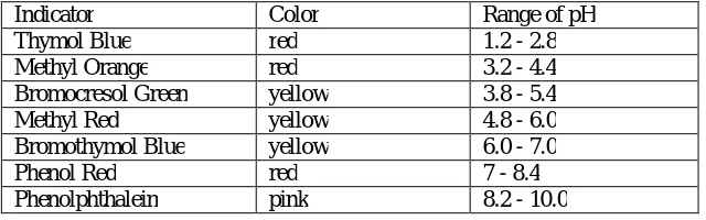
pH can be qualitatively determined by use of indicator. An indicator is a soluble dye whose color is sensitive to pH. Indicator colors change over a relatively short pH range, they give the approximate pH of solution.Commonly used indicator is a litmus paper, which changes red to blue in the pH range 8 to 10. The other pH indicator is the acid - base indicator which is usually weak acid or base. For example, methyl red is a pH indicator used to identify pH values between 4.8 and 6.0. The other commonly used indicators are given in Table 1. Any one indicator is useful for determining pH only in the region where it changes color [7].
Indicator Color Range of pH
Thymol Blue red 1.2 - 2.8
Methyl Orange red 3.2 - 4.4
Bromocresol Green yellow 3.8 - 5.4
Methyl Red yellow 4.8 - 6.0
Bromothymol Blue yellow 6.0 - 7.0
Phenol Red red 7 - 8.4
Phenolphthalein pink 8.2 - 10.0
Table I: Commonly used pHindicators
The instrument forthe pH measurement was made by Arnold Beckman in the year 1934. He had used simple high-gain amplifier made using two vacuum tubes. But he had faced many difficulties in potentiometric measurement. Main problem was caused by high internal resistance of glass electrode, which makes measurement difficult. Although many years passed since then, design of pH meter follow the same general idea - glass and reference electrodes, high gain voltage amplifier. The modern pH meters use digital technology and give accuracy better than 0.01. An electronic pH meter is used for more precise measurement. It determines the pH from the electrical potential difference between the glass and reference electrodes.
C. Aging of Electrode
An electrode senses charge on ions and converts it into electric potential signal. The magnitude of signal is of the order of few millivolts and decreases with the aging of electrodes. For instance, a new pH electrode when placed in a known standard solution with a value of pH 7.01 shows output of -5.1 mV. After few days the electrode shows -5.5 mV for the same solution. The error of 0.4 mV is the drift of signal. The corresponding error in pH value is very small (0.01). However, if the drift exceeds about -30 to -35 mV, the electrode gives unstable output, and such electrodes need to be repaired or replaced [8].
As glass electrode ages, its resistanceincreases. It is mainly caused by deposition of heavy metal ions, proteins and organic materials on the glass surface.This resistance change alters the electrode potential. The electrode with high resistance gives noisy, unstable and erratic readings. If the electrode is used in viscous solutions such as oil and paint then its capacitance decreases.Such electrodes show slow response to the change in pH value. For this reason, it is necessary to measure the resistance and capacitance regularly.
II. RELATED WORK
In 1906, Haber and Klemensiewicz, had constructed the glass electrode whose potential dependent on activity of H+ ions. Glass electrode technology hasnot changed much in the past century. With all the technological advancements of the last decade, glass electrode manufacturing remains an art. The special glass body of the electrode is blown to its configuration by glass blowers. The process of glass blowing is critical and needs skilled technician.The thickness of the glass determines its resistance and affects its output potential.
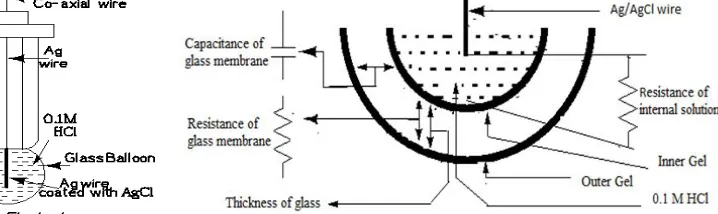
Figure 1 shows the construction of glass electrode. Glass electrode is constructed from the special composition glass which senses the hydrogen ion concentration. It is typically composed of alkali metal ions. Corning 015 glass consisting of approximately 72% SiO2,22% Na2O, and 6% CaOis widely used in making glass electrode.It withstands high temperature of 1000C or more. It has resistance to corrosive materials and solvents.Glass electrode is made of a glass tube with glass bubble at one end formed by the glass blowing technique. The bubble is filled with 0.1N HCl and silver wire covered with AgCl is immersed into it.
The alkali metal ions of the glass and the hydrogen ions in solution undergo an ion exchange reaction generating a potential difference. The modern glass electrode is combined with a reference electrode and the combination is called the combined electrode. In a combined electrode, there are two electrodes in one body. One portion is called the measuring electrode, and other is the reference electrode. The potential that is generated at the junction site of the measuring portion is due to the free hydrogen ions present in a solution. The potential of the reference portion is produced by the internal element in contact with the reference fill solution and it is maintained at constant value. In summary the measuring electrode delivers a varying voltage and the reference electrode delivers a constant voltage to the meter. The voltage signal produced by the glass electrode is a very small with high output impedance. An amplifier with impedance equal to the impedance of glass electrode is required for the amplification of the pH signal. This is the reason why pH potential is not directly measured by the ordinary voltmeter.
Glass electrode has the capacitance Cg with thin glass as dielectric material and the inner and outer gel membranes act like conducting plates. Charge accumulated on the outer membrane (q) produces the potential difference given by,
V = q / Cg.
Figure 2 shows the intersection of the glass electrode and the corresponding equivalent electronic components. The balloon of glass electrode forms the electrode-electrolyte interface and it is equivalent to the parallel combination of resistor (Rg) of glass and capacitor (Cg) with glass as dielectric [13]. The internal and external ionic solutions form the plates of parallel plate capacitor. The resistance of internal solution (Rint) is in series with Rg and Ag/AgCl wire. The Rg and Cg are given by [13],
R = ρ× d
B , C =
ε × k × A d
Where, ρ=specific resistance, d= thickness, B= cross-sectional area, ɛ0= permittivity of free space, k=dielectric constant, A=surface area of balloon.
The sensitivity and response time of glass electrode depends on the surface area and thickness.
III.ELECTRONIC CIRCUIT DESIGN
The operation of electronic circuit is based on VVR implemented using microcontroller and a JFET. The JFET is a voltage controlled current amplifier. In the present work, commonly available n-channel JFET BFW10 is used [14].The electric field in the channel is controlled by varying the gate voltage. The resistance of channel can be varied by changing the width of channel. VVR is used as external resistor in the 1/400 deflection method. The resistance of glass electrode is measured by this method. The procedure of deflection method is given below:
A. Measurement ofRg
Rg can be measured in following three steps.
1) Deflection Method:Voltage across Rg is measured and it is called full deflection (Vfd) as shown in figure 3(a):
2)1/400Deflection Method:A known variable resistor (Rk) is connected in series with Rg and by varying Rk, the voltage across Rk is reduced to1 400Vfd, as shown in fig 3(b). It is calculated by using potential divider formula,
V = V
400= R
R + R v
Further, value of Rg can be obtained as,
R =(400 × V −V ) × R V
3) At 1/400 deflection position, resistance Rgequals to 400 ×Rk. The value of Rkis obtained by using Ohm-meter.Above method has been used to measure the resistance Rg of glass electrode. The measured Rg of new and old glass electrodes are 400 MΩ and 420 MΩ respectively.
B. Measurement of capacitance (Cg)
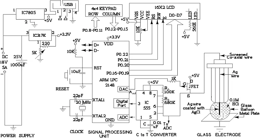
The balloon of glass electrode forms capacitor and it is measured with the use of astablemultivibrator using timer IC555. It works as a capacitance to time conversion circuitas shown in figure 4.
Fig4: Circuit for the capacitance to time conversion
The frequency and periodic time of astablemultivibrator are given by,
+ -Vin
-Vin
S
2 5V
RA
RB
F = 1.44 (R + 2R ) × C
T =(R + 2R ) × C 1.44
If RA= 10KΩ, Cg=100pF, F=10 KHz, then from above equation, RB≈ 680KΩ.
Capacitance (Cg) due to the glass electrode is used as timing capacitor. It is determined from the periodic time of output of multivibrator. Above method has been used to measure the capacitance Cg of glass. Its values for new and used glass electrodes are 60pF and 58 pF respectively. For simplicity in understanding the system, the block diagram of the measurement system is shown in figure 5. It shows the main blocks of resistance measurement unit. The voltage scaled by electrode and VVR is processed and displayed by signal processing and display unit respectively.
Fig5:Block diagram of the measurement system
Figure 6 shows the circuit diagram of the system drawn in XCIRCUIT.It uses 32-bit ARM-7 microcontroller for the operations of data management and modification.
To measure the high resistance of glass bulb either Megger or electronic Ohm-meter can be used. To measure it automatically, electronic variable resistor is implemented using JFET. Resistance between drain and source terminal (RDS) is adjusted to (1/400)RG, and calculated with the use of preloaded look-up table of VGS and RDS.
IV.SOFTWARE DEVELOPMENT
The steps in measurement of parameters are depicted in the flowchart as shown in figure 7.The LPC2148 microcontroller is supported by various commercially available IDEs for compiling and debugging of software code. Keil is widely used IDE for LPC family of microcontrollers. The Keil µvision software development platform has facility of editor, project manager, compilerand generation of Hex code.
Fig7: Flowchart for the measurement of resistance and capacitance
V. CONCLUSIONS
Future Scope
In future, circuit can be enhanced to self-diagnosed pH meter by including pH amplifier in it, and incorporating the software function for solving the Nernst equation. It will give indication to the user about status of the glass electrode.
Acknowledgment: Authors are thankful to the Principal, Modern College, Pune, for providing the laboratory facility.
REFERENCES
[1] Skoog, West D.M., Holler F.J.&Crouch S.R., - Fundamentals of Analytical Chemistry, 8thEdn, Thomson-Brooks/Cole, 2004. [2] ChatwalG. R., AnandS. K., Instrumental Methods of chemical analysis, Himalaya publishing house, 5thEdn, 2008.
[3] CovingtonA. K., Bates R. G. and DurstR. A., “Definition of pH Scales, Standard Reference Values, Measurement of pH and Related terminology”, Pure & Appl. Chem., Vol. 57, No. 3, pp. 531-542, 1985.
[4] BuckR. P., S. Rondinini, CovingtonA. K., BauckeF. G. K., Brett C. M. A., CamõesM. F., Milton M. J. T., MussiniT., “Measurement of pH Definition, Standards, and Procedures”, Pure Appl. Chem., Vol. 74, No. 11, pp. 2169–2200, 2002.
[5] PersatAlexandre, Robert D. Chambers and Juan G. Santiago, “Basic principles of electrolyte chemistry for microfluidic electrokinetics. Part I: Acid–base equilibria and pH buffers”, Lab Chip, Vol. 9, pp. 2437–2453, 2009.
[6] LichStuart t, “pH measurement in concentrated alkaline solutions”, Anal. Chem, Vol. 57, No.2, pp. 514–519,1985. [7] DeanJohn A., Lange's Handbook of Chemistry, Handbook Publishers Inc., 15thEdn, 1999.
[8] Murphy Vincent G., Barr Ronald E., Hah Allen W., “Control of Electrode Aging by a Periodic Anodization Technique”,Advances in Experimental Medicine and Biology, Vol. 75, pp 69-75,1976.
[9] Bhadane P. K., BhangaleS. P. and Hira M. S., “Development of microcontroller based inexpensive water analyzer: A photoelectric design approach,” Int. J. of Innovative Research in Science, Engineering and Technology (IJIRSET), Vol. 3, no. 3, pp.10591-10599, 2014.
[10] Bhadane P. K., BhangaleS. P., “Development of microcontroller based two channel colorimeter for the analysis of cobalt in water,” Int. J. of Engineering research & technology (IJERT), vol. 3, no.4, pp.564-569, 2014
[11] Bhadane P. K., BhangaleS. P., “Development of microcontroller based two channel colorimeter for the analysis of cobalt in water,” Int. J. of Engineering research & technology (IJERT), vol. 3, no.4, pp.564-569, 2014
[12] Bhangale S.P.,“Development of Embedded System Based Colorimeter for the Analysis of Copper in Waste Water analysis”,International Journal of Innovative Research in Science, Engineering & Technology (IJIRSET), Vol. 3, Issue 9, pp. 17869-17876, 2014.
[13] Bonde S.L., Bhangale S.P., Bhadane P.K.,“Investigation of some electronic properties of combined pH electrode”,International Journal of Engineering Research & Technology (IJERT), Vol. 3, Issue 9, pp. 1114-1116, September- 2014.
[14] http://www.alldatasheet.com/datasheet-pdf/pdf/77365/MOTOROLA/BFW10.html.
BIOGRAPHY
Prof. Sharad R. Chaudhary is working as Vice-Principal and Head of the Department at Modern College, Pune (India). His area of research interest is embedded systems and e-Waste Management.
Prof. (Mrs.) Suchita P. Bhangale is working as Assistant Professor of Electronics at NowrosjeeWadia College, Pune (India). She is pursuing her Ph.D. work in the field of analytical instrumentation.