Shape Optimization of a Nuclear Fuel Rod Support Structure
K. N. Song *l), K. H. Yoon 1), K. J. Park 2), B. S. Kang 2), and G. J. Park 2)
1) Korea Atomic Energy Research Institute, P.O. Box 105, Yusong, Taejon 305-353, Korea
2) Automatic Design Laboratory, Department of Mechanical Engineering, Hanyang University, 17, Haengdang-Dong, Sungdong-Gu, Seoul 133-791, Korea
A B S T R A C T
In pressurized light water reactor fuel assembly, spacer grids support nuclear fuel rods both laterally and vertically. The fuel rods are supported by spacer grid springs and grid dimples that are located in the grid cell. The support system allows for some thermal expansion and imbalance of the fuel rods. The imbalance is absorbed by elastic energy to prevent coolant flow-induced vibration damage. Design requirements are defined and a design process is established. The design process includes mathematical optimization as well as practical design method. The shape of the grid spring is designed to maintain its function during the lifetime of the fuel assembly. A structural optimization method is employed for the shape design. Since the optimization is carried out in the linear range of finite element analysis, the optimum solution is verified by nonlinear analysis. A good design is found and the final design is compared with currently existing designs. Commercial codes are utilized for structural analysis and optimization.
INTRODUCTION
In PWR (Pressurized light Water Reactor) fuel assemblies, spacer grids are important components to laterally and vertically support nuclear fuel rods [1-3]. It is required that nuclear fuel should maintain mechanical soundness for safety and economical efficiency during operation. The loss of mechanical soundness of nuclear fuel is generated by excessive deformation and damage of a spacer grid, fuel rod, and hole down spring. Since the most frequent appearance is deformation and damage of fuel rods, they have been main topics in the safety research of the nuclear fuel operation. Therefore, the spacer grid has been steadily studied and improved. A spacer grid for a nuclear fuel assembly has grid springs and dimples. They contact fuel rods and absorb vibration impact during reactor operation, inserting process of the fuel rods and shipping [1-3].
General roles of the spacer grid assembly are: (1) providing lateral and vertical support for fuel rods (2) maintaining fuel rod space under accidental and operational loading conditions (3) promoting the mix of the coolant (4) keeping the guide tubes straight so as not to impede the control rod insertion under any normal or accidental conditions.
In this research, new design requirements are proposed for mechanical characteristics such as deflection and force on the spacer grid spring. The force-deflection curve for a spring has to be linear in the range up to 40N of the external force and 0.4mm at the initial interference between the spacer grid spring and nuclear fuel rod. Conceptual design of the spring is proposed by engineering sense. Nonlinear finite element analysis is utilized to help the design process. The analysis is conducted by a software system called ABAQUS 5.8 [4].
After a conceptual design is established, structural optimization is applied to the detailed shape design of the spring. Mathematical optimization has been well developed for linear analysis. However, it is not well established yet for nonlinear analysis [5-8]. Therefore, the optimization is performed in linear range. An optimization problem is formulated for the design of the spring. A commercial code named GENESIS is adopted for the optimization process [9]. The shape optimization module of the software is used. The optimum design is analyzed again in nonlinear range and the result is compared with the existing design and discussed. ABAQUS is utilized for the evaluation [4]. A good design is found and discussed.
THE S P A C E R GRID S P R I N G
The structural grids support the fuel rods both laterally and axially with a friction grip. Each cell in the spacer grid employs a fuel rod support system consisting of two orthogonal sets of two dimples and a spring. The support system not only allows the fuel rod to move through the cell axially as necessary for thermal and rod growth movements, but also follows fuel rod diametral changes in operation while maintaining alignment.
4.
SMiRT 16, Washington DC, August 2001 Paper # 1671
F e a t u r e s a n d S t r u c t u r a l F u n c t i o n s
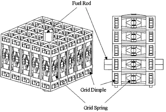
A schematic view of a grid set is illustrated in Fig. 1. A spacer grid for a nuclear fuel assembly has grid springs and opposing dimples which contact a fuel rod and cushion any vibration impact. The impact is generated between the fuel rods and the grid springs and dimples during reactor operation and during fuel assembly shipping. Also, external forces are imposed on the springs during insertion of the fuel rod into the spacer grid. Because the grid dimples are relatively large in strength compared to the grid spring, their deformation can be negligible.
Fuel Rod
t.3 / i t_l
d D i m p l e / ~
Grid Spring
Fig. 1 Schematic View of a Spacer Grid Set
The general structural functions of the spacer grid assembly are as follows: First, the structural grid assemblies provide both lateral and vertical support for the fuel rods. The support system allows for differential thermal expansion and growth of the fuel rods, and retains them with sufficient spring contact force to prevent coolant flow-reduced vibration damage. However, it should not locally overstress the fuel rod clad. In a recent design, the spring system acting on the fuel rod is balanced to mitigate the tendency for fuel rods to bow, by favorably distributing axial loads on the rods. Second, the grid design maintains the spacing under both accidental and operational loading conditions to maintain coolability of the fuel rod lattice. The pitch of the fuel rods in the core is a carefully selected parameter which has a major effect on the nuclear and thermal/hydraulic performance of the core. Reducing the grid cell pitch and perpendicularity tolerance results in increased thermal/hydraulic margin. Third, the grids must support the guide thimbles to keep them sufficiently straight so as not to impede control rod insertion under any normal or accidental conditions. Fourth, the grid makes the water channel between the nuclear fuel rods to improve coolant mixing through the core. Coolant mixing in the hottest fuel assembly spans, between the structural grids, is the primary function of the intermediate flow mixers. Finally, the grid must support the instrumentation tube sufficiently straight so that plant neutronic instrumentation can be freely inserted and removed from the tube even after the design lateral loading conditions.
D e s i g n R e q u i r e m e n t s
two categories: displacement and force conditions. I. Displacement requirement
During fabrication, the rod is pulled into each spacer grid cell having a height difference of about 0.4 mm and the grid spring has the same deflection. The height difference is caused by manufacturing tolerances. After insertion of the rod, the performance of the grid spring can be deteriorated if the grid spring is out of position. The grid spring is designed to have an elastic range of up to 0.4mm deflection of the spring characteristics curve. This requirement is defined in linear range. However, slight nonlinear deformation is allowed. Later, it will be shown that the requirement cannot be satisfied by the given configuration. Thus, the spring is designed to have maximum flexibility within the given range. Further investigation is required for the definition.
II. Force requirement
Throughout the lifetime of reactor, the grid spring loses 92% of its strength due to the irradiation-induced relaxation. The irradiation induced property changes are strength and ductility change, stress relaxation, and growth. If they are not considered in the design stages, the integrity of the grid can be jeopardized. During reactor operation, the unit grid spring endures flow-induced vibration of 2N. The spring should normally perform up to 25 N. The design of all grid assembly parts should limit flow-induced vibration so it will not lead to vibration-induced fatigue, fretting, and out of position problems. During shipping, the grid spring should withstand vertical and lateral accelerations without allowing the fuel rods to shift or the grid spring to deform permanently. Therefore, the requirement of 25N should be increased to include the unknown disturbances.
Putting these various design requirements together, the mechanical characteristic curve for a good spring has to be linear in the range of up to 40N and 0.4mm at the initial interference between the spacer grid spring and nuclear fuel rod. Then the spring constant is about 100-150 N/mm.
APPLICATION OF SHAPE O P T I M I Z A T I O N
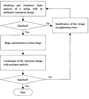
A spring in a grid set is analyzed and designed. The flow of the design process is defined and illustrated in Fig. 2. Because various aspects are involved, it is extremely difficult to define each step with an automatic design process. Instead, a practical design using engineering sense is very efficient in some steps. The flow in Fig. 2 includes those characteristics. Each step is explained in the following sections:
C o n c e p t u a l D e s i g n
At first, the spring is designed by engineering intuition. The spring should fit in the structure in Fig. 1. It is difficult to have drastic shape change in optimization. The drastic shape modification can be made in this step. Design requirements in the previous chapter are defined in a linear range. The spring slightly reaches the plastic (nonlinear) range. Therefore, the conceptual design is carried out with nonlinear analysis. The design is directed to have maximum flexibility and lower maximum stress by trial and error. A spacer grid cell with imposed displacement boundary conditions is modeled for analysis of spacer grid spring characteristics. The geometric model is created by using I-DEAS ms7.0 [10]. Because of symmetry, only a quarter of the structure treated as thin shell elements is analyzed using ABAQUS 5.8 [4].
For the spring characteristics satisfying the foregoing proposed design requirements, the stiffness of the spring is selected as a performance measure. The stiffness is computed by the ratio of the reaction force developed at the final load step and the prescribed displacement. The linear range of the stiffness is also selected as a performance measure. The stiffness is related to the maximum stress in a model with nonlinear material property. The linearity of the stiffness is insured when the maximum stress does not exceed the yield stress of the spring at the load step. The final design is illustrated in Fig. 3.
The analysis is carried out in 9 load steps and the maximum displacement prescribed at the final step is 0.9 mm. Fig. 3 shows the fringe plot of the Von-Mises stresses on the performed structure at 0.3 mm displacement step. The force- deflection response of the grid spring at the initial design is shown in Fig. 4.
i.dl
F
No Modeling and Nonlinear finite analysis of a spring with an arbitrarily conceptual design
Modification of the design in engineering sense
Shape optimization in linear range
Verification of the Optimum design with nonlinear analysis
?
(stop)
No
Fig. 2 Flow of the Defined Design Process
m e.:N'~
I~il: "-"2-: ~ ' ~ :
/i iil ~'~~ ~i!~
l
!
!
!
Fi~. 3 The Fringe Plot of the Von-Mises
F-D Curve
. j -
I
0 0.1 0.2 0.3 0.4 0.5 0.6 0.7 0.8
Deflection(mm)
Fig. 4 The Force-deflection Characteristic
Curve of the Conceptually Designed Spring
D e t a i l e d D e s i g n
The overall shape is determined in the conceptual design process. The detailed design is carried out by shape optimization. A slight modification of the shape is made. As mentioned earlier, the optimization is performed in a linear
range. Generally, the objective function in structural optimization is defined by the weight of the structure. However, it has been proved that the structure does not have a feasible solution for allowable stress with the given configuration in Fig. 1 [7]. Therefore, the problem is formulated with the maximum stress as the objective function.
The optimization problem is defined as follows:
F i n d d e s i g n v a r i a b l e s
M i n i m i z e m a x i m u m cr (1)
S u b j e c t to 6 - 0.4 - 0 (2)
Fspring - 40 - 0 (3)
Where rr is stress, ~ is the deflection at the center of the spring and
Fw,.~,g
is an external force on the spring. The displacement condition in Eq. (2) is from the first requirement and the force condition in Eq. (3) is from the second requirement. The optimization problem in Eq. (1) is converted to make a smooth problem as follows [5-6, 11 ]:F i n d M i n i m i z e S u b j e c t to
d e s i g n v a r i a b l e s
cr-fl___ 0
6 - 0 . 4 = 0
Fspring - 40 - 0
(4)
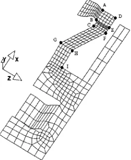
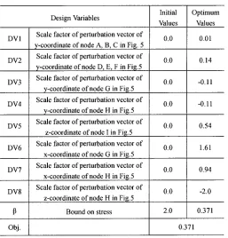
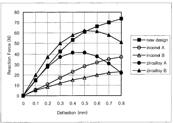
A quarter of the finite element model is illustrated in Fig 5. Eight design variables are selected. The design variables are indicated in Fig. 5 and Table 1. Optimization is carried out by GENESIS 6.0 [9]. The initial design for the optimization is the design result of the conceptual design. The results of the optimization are shown in Fig. 6 and Table 1. The maximum stress exceeds the yield stress of 0.382 GPa. Because a little plastic deformation is allowed, the design is considered acceptable. A nonlinear analysis is performed with the optimum design. The result is illustrated in Fig. 7. It is noted that the optimum design is more flexible than the initial design. The new design is compared to current existing designs by nonlinear analysis. The comparison is illustrated in Fig. 8. The performance of the spring is quite improved.
G t:
-- initial design - optimal design I
80
7O
60 J ~ " " ~ ~ "
50 t " ' " ~
p u_ 40
c-" =o
30 "
r r "
20
o!
~..._.~119
0 0.1 0.2 0.3 0.4 0.5 0.6 0.7 0.8 Deflection (ram)
Fig. 7 Result of Spring Characteristic Curve
Table 1 Result of Shape Optimization
DV1 DV2 DV3 DV4 DV5 DV6 DV7 DV8 Obj. Design Variables
Scale factor of perturbation vector of y-coordinate of node A, B, C in Fig. 5 Scale factor of perturbation vector of y-coordinate of node D, E, F in Fi8.5 Scale factor of perturbation vector of
y-coordinate of node G in Fig.5 Scale factor of perturbation vector of
y-coordinate of node H in Fig.5 Scale factor of perturbation vector of
z-coordinate of node I in Fig.5 Scale factor of perturbation vector of
x-coordinate of node G in Fig.5 Scale factor of perturbation vector of
x-coordinate of node H in Fig.5 Scale factor of perturbation vector of
z-coordinate of node H in Fi8.5 Bound on stress
.g
0
0
0
0
0
o o
o!
,,•...I
I/,£/-q..
0 0.1 0.2 0.3 0.4 0.5 0.6 0.7 0.8 Deflection (mm)
new design 0 inconel A
• ~. inconel B zircalloy A ~,, zircalloy B
Fig. 8 Comparison with Commercial and Developing Spring
CONCLUSIONS
I. New design requirements for spacer grid spring are defined for manufacturing and working conditions.
II. A design process is proposed for the spacer grid design in a practical way. Conceptual and detailed designs are defined appropriately with linear and finite element analyses and optimization. Basically, the design is directed to enhance the flexibility of the spring.
III. In the conceptual design, the overall shape of the grid spring is determined. Nonlinear analysis is exploited to help the decision making process which is made based on engineering sense.
IV. Shape optimization is employed for the detailed design. The maximum stress of the spring is minimized while the design requirements are satisfied.
g . Because the shape optimization is conducted in a linear range, the nonlinear performance of the optimum design is evaluated. It is found that the new design is much more excellent than the current designs.
VI. More investigation is needed for the design requirements because they are only defined for a linear range.
ACKNOWLEDGEMENTS
This Project has been carried out under the nuclear R&D program by MOST. And also, this research was supported by Center of Innovative Design Optimization Technology, Korea Science and Engineering Foundation and Brain Korea 21 Project in 2001. The authors are thankful to Mrs. MiSun Park for her correction of the manuscript.
REFERENCES
Atomic Energy Research Institute, Korea, 1999. (In Korean)
2. Walton, L.A., "Zircaloy Spacer Grid Design," Transactions of the American Nuclear Society, Vol. 32, 1979, pp. 601-
602.
3. Larson, J.G., "Optimization of The Zircaloy Spacer Grid Design," Transactions of the American Nuclear Society, Vol.
43, 1982, pp. 160-161.
ABAQUS/Standard Version 5.8 User's manual, Hibbitt, Karlsson, and Sorensen, Inc., Pawtucket, Ill, 1998.
5. Arora, J.S., Introduction to Optimum Design, McGraw-Hill Book Company, New York, 1989.
6. Haftka, R.T., Gurdal, Z., Elements of Structural Optimization, Kluwer Academic Publishers, Netherlands, 1992.
7. Choi, S.K., Design of a Nuclear Fuel Rod Support Grid Using Axiomatic Design, M.S. Thesis, Hanyang University,
Korea, 2001. (In Korean)
8. Park, G.J., "Impact Analysis of Spacer Grid Assembly and Shape Optimization of Spacer Strap," KAERI Research
Report, Hanyang University, Korea, 2001. (In Korean)
9. GENESIS Version 6.0 User's Manual, VR&D, Colorado Springs, CO, 2000.
10. I-DEAS Master Series 7, Online Help Bookshelf, SDRC, Milford, OH, USA, 1999.
11. Taylor, J.E., and Bendsoe, M. P., "An Interpretation For Min-Max Structural Design Problems Including a Method for
Relaxing Constraints", Int. J. Solid Structures, Vol. 20, No. 4, 1984, pp. 301-314.