Division V
Seismic SSI Analyses in the Nuclear Industry: Comparative Case Study for
Time Domain vs. Frequency Domain
Payman Khalili Tehrani1, Benjamin Kosbab1, Huy Tran2
1
Principal Engineer, SC Solutions Inc., USA
2
Senior Engineer, SC Solutions Inc., USA
ABSTRACT
The nuclear industry has been a pioneer in recognizing the importance of Soil-Structure Interaction (SSI) and its effects on the dynamic response of structures and components during an earthquake. Equivalent linear analysis in frequency domain (ELFD) is the current state of practice for performing seismic SSI analysis of nuclear facilities. While the ELFD method produces reliable results for small to moderate intensity ground motions, it may not be suitable to analyze structures under large seismic events. Nonlinear analysis in time domain (NLTD) is more suitable for a wide range of seismic events by allowing explicit modeling of soil and structure material nonlinearities, including degradation and damage, as well as soil-structure interface nonlinearities.
It is recognized that the key to building industry-wide confidence in time domain approaches is to verify them by making the modeling assumptions equivalent to those of the ELFD approach. In other words, there is a need for a successful equivalent linear analysis in time domain (ELTD). In this study, a typical partially-embedded Pressurized Water Reactor (PWR) nuclear containment building under a seismic event, scaled to various intensities, is analyzed with various approaches. A novel treatment of damping is used for ELTD to achieve nearly frequency-independence and thus allow direct comparison with ELFD. Material and interface nonlinearities are then introduced into the time domain model to perform the NLTD analysis and compare the results to equivalent linear analyses. The time domain response history analyses (i.e. ELTD and NLTD) are performed in LS-DYNA while the ELFD analyses are performed in SC-SASSI using the direct method of substructuring. The study is “blind” in the sense that no post-analysis model iteration was performed to calibrate or refine the response alignment.
It is shown that the obtained seismic responses, presented as in-structure response spectra (ISRS) at different locations within the containment building, are equivalent for both ELTD and ELFD analyses, while the seismic response from NLTD deviates for large seismic events. Linear analyses generally over-predict the response versus nonlinear analysis, but the observed differences are dependent on the frequency range of interest, the site soil and structural properties of the SSI system, as well as the characteristics of the ground motion under study.
INTRODUCTION
that may be encountered in nuclear applications. Even though the time domain SSI approaches have been evolving and used in other industries, e.g. oil and gas, transportation, and water [11], they have not gained enough momentum for widespread use in the nuclear industry. The latter has persisted despite recent advancements in nuclear industry itself ([4] and [9]). Extensive industry investments in the development and validation of ELFD approach over decades have built a body-of-knowledge for confidence of its use that has not yet been matched by nonlinear methods. Therefore, the transition to accepting nonlinear methods will be aided by utilizing verification which draws upon that ELFD investment. As such, the authors believe that the development of a successful equivalent linear approach in time domain (ELTD) can play an important role for the industry to make the transition towards nonlinear approaches.
There have been two main issues with the time domain SSI approaches impeding its widespread use in the nuclear industry: (1) efficient and reliable modelling of an infinite soil domain; and (2) frequency independent hysteretic material damping. The development of perfectly matched layers [2] acting as non-reflecting boundaries for the soil FE domain has resolved the first issue for linear domains. Alternatively, utilizing the computational efficiency afforded today, one can make the domain boundaries far enough from the structure to utilize the radiation damping within the soil domain itself and alleviate the undesired reflections. The latter approach can be used for nonlinear analyses as well. The hysteretic damping is explicitly modelled in the NLTD approach but formulating a frequency independent damping in time domain is necessary for the success of the intermediate ELTD approach. The conventional simplified treatment of damping in time domain, e.g. Rayleigh formulation, is not able to resolve this issue. Drawing upon the original work in the area of viscoelasticity by Biot [3] and more recent developments by other researchers ([14], [17], and [21]), the authors successfully simulated the frequency independent viscoelastic response of soils in time domain.
In this study, the SSI analysis results using all three approaches (i.e. ELFD, ELTD, and NLTD) for a typical PWR reactor building are compared. The ELTD approach will be verified against ELFD. Furthermore, the limitations of equivalent linear approaches will be highlighted in the comparative study and through analyses with scaled ground motions. Finally, the explicit modelling of structural concrete cracking will be demonstrated and the results will be compared to those based on recommendations of ASCE 43-05 [1] for equivalent linear approaches.
CASE STUDY DETAILS
In order to compare the results of the three different seismic SSI analysis approaches, i.e. ELFD, ELTD, NLTD, a typical PWR reactor building was selected for analyses. It was embedded in a typical U.S. nuclear site and subsequently excited with a ground motion scaled to different intensities. The details of the model components are briefly described in this section.
PWR Structure
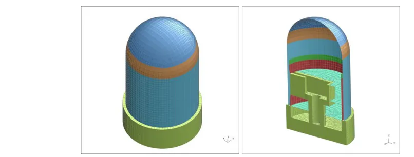
Figure 1. Finite Element model of the PWR building used for the comparative study
Soil Site
The generic shear wave velocity profiles for representative U.S. nuclear power plant sites as reported in NUREG/CR-6865 [18] were used to define the site soil properties. The generic profiles and the one selected for this study are presented in Figure 2. In order to trigger SSI effects and the potential effect of site nonlinearities on the ISRS the “Lower Range” velocity profile for “Site IV” was selected for the comparative study. The selected site is 250ft deep and is comprised of relatively soft soil deposit among typical nuclear sites. It was assumed that the soil deposit is underlain by an elastic half-space with a shear and compressive wave velocities of 2000ft/sec and 4250ft/sec respectively.
Figure 2. Typical shear wave velocity profiles for nuclear power plant sites per NUREG/CR-6865 (left), selected site for the comparative study along with employed layer discretization (right)
Input Ground Motion
Figure 3. Standard spectral shapes per US NRC Regulatory Guide 1.60
SSI ANALYSIS IN TIME DOMAIN
Both structure and soil domain are discretized and represented via finite elements in time domain approaches. The global FE model used for time domain analyses is shown in Figure 4. The three components of ground motions are applied simultaneously at the base of the soil domain as rock outcrop. Transmitting boundary conditions are applied at the base and the side boundaries are modeled far enough from the structure so their response does not affect the SSI behavior to efficiently model an “infinite” soil domain. The seismic waves propagate through the continuum soil domain and excite the PWR reactor building through soil-structure interfaces. The equations of motion are solved through direct integration in time domain.
The passing frequency requirements for SSI analysis are governed by the FE layer thicknesses and the soil stiffness as they relate to transmission of vertically propagating plane waves. For each soil layer, the maximum FE layer thickness was calculated based on the desired minimum passing frequency of 30Hz and the degraded shear-wave velocity.
Equivalent Linear Time Domain Analysis (ELTD)
In the ELTD approach both structure and soil are modelled using a viscoelastic material model with hysteretic damping. The soil and structure response, where in contact, is fully coupled by tying their FE meshes together at their interface. The main challenge associated with the equivalent linear analysis in time domain is achieving a frequency independent damping, i.e. true hysteretic material response.
Hysteretic Material Damping in ELTD analyses: The equivalent linear analyses in time domain have historically suffered from simplified treatments of damping in civil engineering practice. This has played an important role in lack of confidence in time domain approaches for SSI analyses in nuclear industry and prevented them from being seriously considered as a viable alternative.
Rayleigh damping has been widely used in the linear analysis of structures in other industries, e.g. transportation industry. Utilizing the Rayleigh formulation and its derivatives/extensions, the analyst can control damping at a limited number of target frequencies. This may be appropriate for the analysis of structures whose dynamic response is governed by significant contribution from a limited number of modes as in a simple highway overpass. On the other hand, seismic SSI analyses in nuclear industry are usually performed on relatively complicated structures to obtain demands not only on the structural components but also (and perhaps more importantly) on the mechanical and electrical equipment and distribution systems. These equipment and systems are necessary for the safety of the plant during and following a major event. As such, damping should be controlled over a wide range of frequencies which makes the incorporation of frequency-independent damping into linear SSI analyses a necessity. This can be done by modelling the hysteretic response of soil and structure.
The consideration of cyclic energy dissipation, i.e. loss as part of the material response has long been formulated in viscoelastic material models. The loss modulus would be frequency independent in an ideal hysteretic model. The challenge with ideal hysteretic models is that they are non-causal which means that the system response precedes the excitation which is not physical. It is understood that the storage and loss of a dynamic system cannot be defined independently in order to have a causal hysteretic model. In order to circumvent the non-causality of the ideal model, Makris [13] modified the loss modulus of the ideal model and formulated a causal hysteretic model. The shortcoming of Makris’s model is that it is singular at the static limit (ω = 0) and its storage modulus may become negative which is not physical. The compromise seems to be the Biot model which is a causal and physical linear model. Both loss and storage of the Biot model are frequency dependent but one can achieve a nearly frequency-independent response by carefully selecting the values of the input parameters of the model. The latter model was used for ELTD analyses in this study.
Nonlinear Time Domain Analysis (NLTD)
In the NLTD approach an effective pressure dependent plasticity model was used to model the soil response where the response of the granular material under building’s weight is different in comparison to the free-field soil outside the structure’s stress zone of influence. The Masing rule [16] is used in the selected plasticity model to define the hysteretic response of the soil. Additionally, penalty based contact algorithms were used at the interfaces to couple the soil-structure response. The contact surfaces would allow for modelling the potential nonlinear sliding and gapping at the interface. Finally, the structure was assumed to be linear elastic.
larger strains where the stress in the soil approaches a limiting strength, and linearization becomes problematic.
The shear stress versus shear strain curve is the key property in time domain analysis, and this has to be derived to best replicate the behavior of the soil over the expected range of shear strains. Degradation curves reported in literature are usually used for dynamic analyses with an inherent assumption that the soil shear strength would not be mobilized during seismic events. The stiffness degradation curves reported in the literature are valid up to shear strain values of approximately 0.35 to 0.5% [5] and usually do not produce correct shear strength values. On the other hand for limit state analyses, e.g. slope stability and foundation bearing capacity, the focus is shifted to accurate characterization of material shear strength along with approximate secant stiffness. In general, and for large seismic events and/or soft sites in particular, the stress-strain curve should be valid from very small strain consistent with the material’s initial stiffness to very large strain consistent with the dynamic shear strength of the soil.
Recognizing the limitations of conventional simplifications, a hybrid method was proposed in [22] whereby the stress-strain relationship is built by combining the small- and large-strain constitutive relationships.
T
he transition from small strain region to large strain region in the methodology presented in [22] results in a tangent slope discontinuity on the shear stress versus shear strain curve. This discontinuity may be problematic when used in FE material models especially if tangent stiffness is not degrading with shear strain. A new formulation has been devised for the large strain region so that the final hybrid curve has a smooth transition from small strain to large strain region [12].The latter hybrid stress-strain relationship was used for NLTD analyses in this study. Soil stiffness degradation curves from EPRI 1993 [6] along with the shear strength parameters of the soil were used to define the yield surface for the plasticity model. Reasonable values of shear strength parameters, i.e. cohesion and friction angle, were assumed for soil layers consistent with their shear wave velocity. An example of the application of the hybrid approach to combine the small strain response of the soil (G/Gmax curve) with the dynamic shear strength of the soil (corrected for strain rate effects) is shown in Figure 5.
Figure 5. Hybrid approach for obtaining soil shear stress vs. shear strain
SSI ANALYSIS IN FREQUENCY DOMAIN
free-field soil, frequency-dependent transfer functions are generated. Input motions consistent with base rock motion and the soil layering are applied as free-field response (at the surface in this study), and seismic waves are propagated through the soil to excite the structure through the soil-structure interface at the interaction nodes. The equations of motion are solved in the frequency domain. The Fourier transform of the input motion is multiplied by the transfer function for the output location of interest to obtain the response in frequency domain. Subsequently, the inverse Fourier transform is applied to produce the output response in the time domain.
The direct method of sub-structuring, i.e. flexible volume method was utilized for the ELFD analysis in this study. There were a total of 34 soil layers in the model and the structure was embedded in the top 12 layers. The analysis had approximately 11,000 interaction nodes.
SEISMIC WAVE PROPAGATION VERIFICATION – SITE RESPONSE
Prior to performing 3D SSI analyses, the employed soil constitutive models for ELTD and NLTD approaches were verified through 1D Site Response Analyses (SRA) and comparison to the results obtained from standard SRA tools. SHAKE [20] was used to produce the reference free-field site response via the ELFD approach while DeepSoil [8] was used to produce reference free-field response via NLTD. The seismic wave propagation problem was also analysed in LS-DYNA [7] by shaking a soil column discretized with solid finite elements in which each soil layer was represented with a single solid element. Boundary conditions were applied to simulate the infinite layer system. The results at the base of the mat foundation level (-44.3ft) and for a horizontal component of the ground motion are presented in Figure 6 as a representative case. The plot on the left shows a good agreement between the response spectra obtained from SHAKE (ELFD) and the ELTD soil column in LS-DYNA. The latter verifies the nearly frequency independent response of the viscoelastic model devised for ELTD analyses. Additionally the plot on the left shows that the response obtained from NLTD soil column analysis is different than the equivalent linear response for this ground motion and site. In order to verify the NLTD wave propagation, the SRA was repeated in DeepSoil and the result was compared to that of the NLTD soil column as presented in the plot on the right. It can be seen that there is a good agreement between the two NLTD responses over a wide range of frequencies. Observed differences are in part due to the internal curve fitting that DeepSoil performs on the user-input soil stiffness degradation curves. Furthermore the soil response pressure dependency was deactivated for the latter comparison due to different formulation in DeepSoil in comparison to the material model used for NLTD. The latter explains the difference between the NLTD curves obtained from LS-DYNA and presented in the two plots in Figure 6.
3D Soil Domain Size Verification for Time Domain Analyses
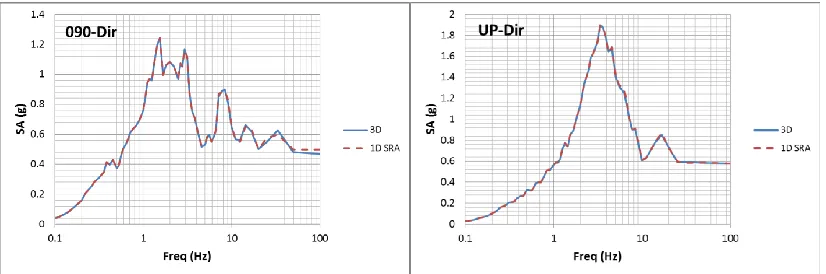
The free-field response obtained from 1D wave propagation analyses was used to verify the 3D soil domain extent for time domain analyses. A sample comparison for NLTD model is shown in Figure 7 for one horizontal component and the vertical component at the base of the foundation elevation. The nearly perfect agreement between the 1D soil column response shaken in all three directions and the far-field response of the 3D soil domain verifies the proper modelling of the remote boundaries in the SSI model.
Figure 7. Comparison of the free-field response from 3D model vs. 1D SRA shaken with three components simultaneously
COMPARATIVE STUDY RESULTS
The results obtained from three SSI approaches, i.e. ELFD, ELTD, and NLTD are compared in this section. Comparison is mainly made using ISRS at a variety of locations inside the PWR reactor building. Additionally the time histories of the mat foundation rocking are compared. It should be noted that the ground motion used in the comparative study was obtained by linearly scaling the motion which was matched to the spectra presented in Figure 3 by a factor of 0.5. The latter scaling was necessary to successfully obtain the equivalent linear properties from SHAKE due to convergence issues. This will be further discussed in the response to ground motion scaling section of the paper.
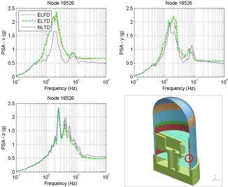
ISRS Comparison
Figure 8. ISRS comparison at the centre of the base mat – ELFD vs. ELTD vs. NLTD
Foundation Rocking
The rocking time history of the mat foundation was obtained from the vertical displacement time histories of two opposite nodes on the foundation perimeter in both x and y directions. The results for all three approaches are presented in Figure 10. There is a good agreement between the ELFD (SC-SASSI) and ELTD (LS-DYNA) results. On the other hand, larger foundation rocking amplitudes are calculated during the main pulses of the ground motion via NLTD approach in comparison to the equivalent linear approaches. Furthermore, there is a permanent rotation of the structure due to soil plasticity and interface nonlinearity at the end of the NLTD analysis which is believed to be a more realistic response.
Figure 10. Rocking time history of the mat foundation – ELFD vs. ELTD vs. NLTD
RESPONSE TO GROUND MOTION SCALING
Both ELFD and NLTD analyses were repeated with varying ground motion intensities and ISRS were calculated. The original spectrally matched ground motion was linearly scaled to obtain analysis input motions of different intensities. The linear scaling of amplitude would not correlate with realistic seismic events at a site due to ignoring the effect of the event magnitude on the frequency content and some other important ground motion characteristics, e.g. directivity etc. Nonetheless, performing SSI analyses with varying motion amplitude can reveal some inherent limitations of the analysis methodology which is the main goal of this section.
Figure 11. Scaled ISRS at the base of the reactor building
CONCRETE CRACKING AND STRUCTURAL NONLINEARITY
The structure was assumed linear elastic in the NLTD analyses. In order to study the effect of structural nonlinearities on the vertical response of concrete slabs (trampoline effect), the highest interior slab modelling was modified in the ELTD model. The relatively coarse slab mesh notwithstanding, layered shell elements with nonlinear material properties were used to model the nonlinear response of the slab. In this modelling approach a number of integration points through the shell thickness, each of which having a different constitutive behaviour, is used to model the composite section. This would allow the modelling of the nonlinear response of composite shell structures like a reinforced concrete slab. The layered shell structure is schematically presented in Figure 12. Confined concrete constitutive law is used for the core layers of the slab confined within the rebar layers while unconfined concrete model is used to model the cover. Mander equations [15] were used to define the constitutive laws for confined and unconfined concrete in this study. A plasticity model with a piecewise linear plastic response capable of capturing the Baushinger effect was employed to model the cyclic response of rebars. The monotonic response of concrete and steel is schematically shown in Figure 12. Further details of the structural constitutive laws are excluded for brevity.
The ELFD analysis was also repeated after replacing the properties of the slab with its cracked section properties as simplistically idealized per ASCE 43-05 [1]. This involved reducing the elastic stiffness by half and increasing the damping from 4% to 7%.
The three components of the same ground motion used for the comparative study were applied to both models.
-45 -40 -35 -30 -25 -20 -15 -10 -5 0 5 10
-4E-3 -3E-3 -2E-3 -1E-3 0E+0 1E-3
Str
ess
(
MPa)
Strain (%)
Figure 12. Nonlinear modelling of the reinforced concrete slab via layered shell approach
indicates two perpendicular cracks in the FE element, i.e. fully cracked. It can be seen that the bottom of the slab is fully cracked in the mid-span while the top of the slab remains elastic (mostly in compression). The cracking in the middle shows that the neutral axis has moved up closer to the top as expected.
Figure 13. Contour plots of concrete cracking at different layers over the shell thickness – slab bottom (Left), slab centre (Middle), and slab top (Right)
The ISRS at a node located at the mid-span of the cracked slab was calculated and plotted against the uncracked results for both the ELFD and ELTD analyses with nonlinear slab. The results are presented in Figure 14. In order to better facilitate the comparison between the equivalent linear and nonlinear modelling of the slab across the two plots, the results in both plots are normalized with respect to the dominant frequency and the maximum spectral acceleration value at the dominant frequency. It can be seen that both the frequency shift and the spectral deamplification due to concrete cracking are similar in both approaches. The latter may suggest that the ASCE 43-05 [1] guidelines for concrete cracking is appropriate when the slab experiences heavy cracking but the results should not be generalized to other areas of the slab with different levels of cracking.
Modelling of nonlinear components using the equivalent linear approach is an iterative process. In this approach a level of cracking, incorporated as an equivalent stiffness and damping, should be assumed a priori and cracking level should be checked based on the stress analysis results afterwards. This iteration is rarely done in practice and even if it is properly done it will be costly. The nonlinear modelling of structural components on the other hand would directly address the extent and distribution of cracking in real time with no need for assumptions and iterations.
CONCLUSIONS
SSI is a key component of the seismic evaluation of nuclear facilities and other critical infrastructure. In this study a typical partially-embedded PWR containment building under a seismic event, scaled to various intensities, was analyzed with various SSI analysis approaches. Equivalent linear approaches in both frequency domain (ELFD) and time domain (ELTD) as well as the nonlinear approach in time domain (NLTD) were used for SSI analyses.
The ELFD approach has been the long-accepted state-of-practice in the nuclear industry. In this study, an equivalent linear analysis with nearly frequency-independent damping formulation was successfully performed in time domain (ELTD). The demonstrated agreement between the ELFD and ELTD results verifies that time domain approaches may provide an attractive alternatives to frequency domain due to their computational efficiency for deeply embedded structures and utility to incorporate more realistic complexities in the analysis. The NLTD analysis results presented in this paper demonstrated that the equivalent linear approaches (ELFD and ELTD) may over-predict the response for large intensity ground motions. Risk analyses and evaluations of existing facilities necessitate realistic response evaluations under large beyond-design-basis and varied seismic events where the site, interface, and structural members may experience large strains and deformations. As such, serious consideration should be given to nonlinear approaches to obtain more representative demands for seismic risk assessment of nuclear facilities.
ACKNOWLEDGEMENTS
The authors would like to thank Michael Perez and Jinquan Zhong of SC Solutions for their support in site response analyses and ground motion preparation respectively.
Some of the results of this study were orally presented at 2016 ASCE-EMI conference in Nashville, TN [10]. The EMI conference had no proceedings so the results, partially or otherwise, have never been published before.
REFERENCES
[1] ASCE/SEI 43-05 (2005). “Seismic Design Criteria for Structures, Systems, and Components in Nuclear Facilities”, ASCE Publications.
[2] Basu, U. and Chopra A. K. (2004). “Perfectly matched layers for transient elastodynamics of unbounded domains,” Int. J. Numer. Meth. Engng; 59:1039 – 1074.
[3] Biot M. A. (1958). “Linear thermodynamics and the mechanics of solids,” Proceedings of the 3rd US national congress of applied mechanics, ASME, New York, NY; 1-18.
[4] Coleman, J. L., Bolisetti, C., and Whittaker, A. S. (2016). “Time- domain soil-structure interaction of nuclear facilities,” Nuclear Engineering and Design,
Vol. 298 : 264-270, ISSN 0029-5493.
[5] Darendeli, M. (2001). “Development of a new family of normalized modulus reduction and materialdamping curves.” Ph.D. Dissertation, Dept. of Civil Eng., Univ. of Texas, Austin.
[6] EPRI. (1993). “Guidelines for Determining Design Basis Ground Motions.” Electric Power Research Institute, Palo Alto, California, USA, Report number: EPRI TR-102293.
[7] Hallquist, J. (2006). “LS-DYNA Keyword User’s Manual, Version 971,” Livermore Software Technology, Livermore, CA.
[8] Hashash, Y. M. A., Musgrove, M. I., Harmon, J. A., Groholski, D. R., Phillips, C. A., and Park, D. (2016). “DEEPSOIL 6.1, User Manual,” Urbana, IL, Board of Trustees of University of Illinois at Urbana-Champaign.
[10] Khalili Tehrani, P. and Kosbab, B. (2016). “Seismic soil-structure interaction analysis of nuclear power plants: time domain versus frequency domain,” ASCE EMI/PMC Conference Book of Abstracts, Nashville, TN, USA.
[11] Khalili Tehrani, P., Kozak, A., Cheng, P., Sedarat, H., Krimotat, A., Bennett, W., and McHenry, M. (2014). “Nonlinear Response History Analysis of Seismic Soil-Structure and Fluid-Structure Interactions for Buried Reinforced Concrete Fluid Storage Structures,” ASCE Engineering Mechanics Conference Book of Abstracts, Hamilton, Ontario, Canada.
[12] Khalili Tehrani, P. and Willford, M. (2012). “A consistent method of defining soil stress-strain curves for seismic site response analysis,” Unpublished manuscript.
[13] Makris, N. (1997). “Causal hysteretic element,” Journal of Engineering Mechanics (ASCE); 123(11):1209 -1214.
[14] Makris, N. and Zhang, J. (2000). “Time domain viscoelastic analysis of earth structures,” Earthquake Engineering and Structural Dynamics.; 29:745 -768.
[15] Mander, J. B., Priestley, M. J. N., and Park, R. (1988). “Theoretical Stress-Strain Model for Confined Concrete.” J. Struct. Eng., 114(8), 1804–1826.
[16] Masing, G. (1926). “Eigenspannungen und verfestigung beim messing,” Proceedings of the Second International Congress for Applied Mechanics, Zurich, Switzerland, pp. 332 – 335 (in German). [17] Muscolino, G., Palmeri, A., and Ricciardelli, F. (2005). “Time-domain response of linear hysteretic
system to deterministic and random excitations,” Earthquake Engineering and Structural Dynamics.; 34:1129 -1147.
[18] NUREG/CR-6865. “Parametric Evaluation of Seismic Behavior of Freestanding Spent Fuel Dry Cask Storage Systems,” U.S. Nuclear Regulatory Commission Office of Nuclear Regulatory Research, Washington, DC 20555-0001.
[19] SC- SASSI Manual, Version 2.1.12, SC Solutions, Inc., August 24, 2016.
[20] SHAKE91 Version 1.10, Department of Civil & Environmental Engineering, University of California, Davis CA, November 1992.
[21] Spanos, P. D. and Tsavachidis, S. (2001). “Deterministic and stochastic analysis of a nonlinear system with a Biot visco-elastic element,” Earthquake Engineering and Structural Dynamics.; 30:595- 612.
[22] Stewart, J. P. and Kwok, A. O. L. (2008). “Nonlinear seismic ground response analysis: code usage protocols and verification against vertical array data,” Geotechnical Engineering and Soil Dynamics IV, ASCE Geotechnical Special Publication No. 181, 181, 1 - 24.