Charlotte, NC, USA, August 4-9, 2019
Division IX (include assigned division number from I to XII)
VISUAL POST-PROCESSING OF ENGINEERING DATA AND REBAR
OPTIMIZATION TOOLS IN THE NUCLEAR FIELD
Vladimir Cerisano Kovačević1, Michele Betti23, Luigi Paone3, Alessandro Valli3, Marina Bottoni45,
Luca Dall’Olio4, Jérôme Beaurain5, Guillaume Hervé-Securgeon5, Ioannis Christovasilis6, Dimitris
Papaevagelou6
1 CEO, Kobe Innovation Engineering, Sesto Fiorentino, Italy ([email protected])
2 Dept. of Civil and Environmental Engineering, Università degli Studi di Firenze, Firenze, Italy
3 Kobe Innovation Engineering, Sesto Fiorentino, Firenze, Italy
4 Alter Ego Engineering, Sceaux, France
5 EDF R&D - Département ERMES, Palaiseau, France
6 Aether Engineering, Firenze, Italy
ABSTRACT
The design of new reinforced concrete (RC) structures is set on a workflow of code-compliant checks which require a huge amount of design and load combinations. Usually the minimum amount of rebar or even the geometric dimensions of the structural elements are unknown when performing the structural analyses, being this data the result of the whole design workflow. This makes the whole process quite demanding and particularly complex when nuclear facilities are to be considered, for which standard regulations (f.i. the Eurocode 2 and 8) are integrated by national annexes and specific recommendations (f.i. the French RCC-CW code).
Preliminary design approach is intended to provide minimum areas of rebar in each section of the structure. In this respect, standard qualified formulations for the verification of 1D elements (mainly columns and beams) and 2D elements (mainly walls and slabs) are often mandatorily proposed in codes and regulations. The need of these implementations must meet both ergonomic purposes, in the pre-processing and, especially, in the post-pre-processing phase, and solve optimization issues, which can be demanding especially in highly congested rebar zones. EDF (Électricité de France), a leader actor in the nuclear energy field, has promoted a partnership with AETHER Engineering (an Italian based company, responsible for the pre-processing part) and KOBE Innovation Engineering (a Spin-off and Start-up from the University of Florence, responsible for the post-processing) in order to deal with those issues inside a dedicated tool (Civil Works Tool).
Regarding the afore-mentioned objectives, the approach here discussed, implemented at this stage and integrated in the Civil Works Tool (CWT), allows, in terms of i) ergonomics, to fully exploit the current web-based technologies in order to handle the interface and the interactivity with the visually represented objects and the related data (mainly reinforced concrete structural elements, their internal forces and reinforcement amounts for each component), and, in terms of ii) optimization, to accompany the standard solution with optimization methods such as the section cut method.
INTRODUCTION
The civil engineering field increased sharply during the last few years with the development of new concepts, the feedback of the previous projects and the evolution of the current regulations. Improvements asking for a constant training of the engineers and leading to the use of more and more complex tools, often from multiple sources and developed only for internal purpose. Tools which need to be imperatively under control in order to ensure the full safety and security of the facilities (we can quote as major examples the nuclear facilities which are in the responsibility of EDF).
At the same time, for economic reasons, the schedule of the construction needs to be always optimized imposing shorter and shorter deliveries for the engineers to express their requirements to the constructors.
This is why it is essential to have a qualified, efficient and user-friendly tool which facilitates the work of the engineer with the automatization of numerical processes linked to the solver (meshing, writing the data and the command files) and proposing optimal solutions for each case. Especially focused on the reinforcement optimization, a major topic impacting both cost and construction, for which several methodologies are used and which may be difficult to fully understand and to properly apply.
To address this challenging, AETHER Engineering, KOBE Innovation Engineering and EDF started a partnership of development on 2018 with the goal to develop a tool based on web technology, also in constant evolution and allowing to take advantage of the latest advances in terms of HMI (Human Machine Interface), and which relies on a mock-up drafted by user-experience. For increased flexibility, the tool exploits the mechanical solver code_aster, which is free, open-source and in constant evolution, to take into account the needs expressed by the users.
In this partnership:
▪ AETHER Engineering is in charge of the development of the interface of the tool and also on the development of all the algorithms regarding the pre-processing part, that contains all the procedures needed to perform the numerical analysis with code_aster,
▪ KOBE Innovation Engineering is in charge of the development of all the algorithms regarding the post-processing part, that contains all the procedure needed to process and evaluate the results of the numerical analysis, including some development in code_aster,
▪ EDF is in charge of the requirements, validations and also of some developments in code_aster, sharing this responsibility with KOBE.
Today, this tool integrates pre-design of reinforced concrete structures and is intended to integrate steel carpentry, masonry structures, timber structures, and more widely, to propose a consensus on the engineering methods of optimization and also on the format of the data to be furnished to the constructors. Always with a goal of mutualization, some works of R&D have begun to find the best solutions to be developed for the import and export functionalities not limited to the solver used (here code_aster).
The whole package was developed with an agile approach, fostering an ongoing exchange with the final users, prioritizing ergonomic requests, allowing to save time and to increase the level of control of the engineer.
THE ENGINEERING AND THE COMPUTATIONAL MECHANICS PROBLEM
account even inside linear analyses; third, because codes and regulations prescribe a high number of possible combinations for each Limit State and impose safety factors to be adopted on material mechanical properties, assuring a very low probability of failure. Inside the sectional verification approach (which differs from the element verification approach, Figure 2), two types of outputs can be produced by the design process: i) the minimum amount of reinforcement necessary to verify the structural element in each section or ii) the verification factor for each section.
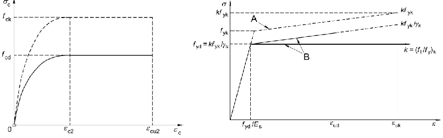
Figure 1. Typical material properties for RC design (ULS): concrete (left) and rebars (right).
In computational mechanics, the problem of the reinforced concrete design is faced inside the classical input-output workflow, based on the results produced by completely agnostic linear elastic finite elements, which are then enriched in significance during the design itself. This will generate point-by-point results for both 1D and 2D elements (even if the principles can be adopted also for 3D elements).
Figure 2. Typical design procedure assumptions for RC elements.
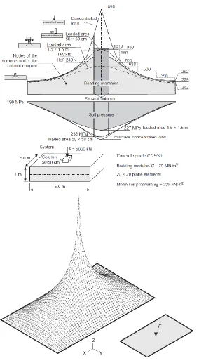
Figure 3. Interpretation of results for a point load and corresponding peaks over singular points. From Rombach (2011).
ALGORITHMS FOR REINFORCED CONCRETE VERIFICATION
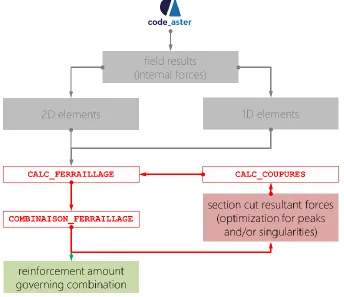
The algorithms developed for the verification of reinforced concrete structural elements are based on the “minimum reinforcement area” calculation method and are implemented inside the EDF’s code_aster open source solver operators and data structures (Figure 4). They comprise:
▪ CALC_FERRAILLAGE, with the enhancement of the existing command through the inclusion of the possibility to perform calculation over 1D elements;
▪ COMBINAISON_FERRAILLAGE, which enables the fast calculation of the reinforcement based on the methods implemented in the CALC_FERRAILLAGE command, giving as output the minimum reinforcement amount for each combination and the governing combination id;
▪ CALC_COUPURES, a macro command which allows the calculation of resultant forces over a section line, chosen for the optimization of reinforcement in that point of the model.
Figure 4. Workflow for the calculation and optimization of reinforcement for 1D and 2D elements. In red the commands that were developed inside this project so far.
My, Mz, N) must be considered when dealing with design automation, such as in a FE code. First, some hypotheses on the longitudinal reinforcement distribution on the cross-section can be considered. For beams, we compute only the reinforcement in tension, while the compressed area is being neglected. For columns, we consider that reinforcement is equally distributed on the cross-section (double symmetry). The general case being too complicated to be solved numerically (or demanding too much computational time), an analytical domain proposed by Bresler (Bresler, 1960) is used:
(
𝑀
𝑦𝑀
𝑅𝑦)
𝑎
+ (
𝑀
𝑧𝑀
𝑅𝑧)
𝑎
≤ 1
(1)where 𝑀𝑟𝑦, 𝑀𝑟𝑧 are the ultimate bending moments around local axes 𝑦 and 𝑧 under the normal effort 𝑁 and 𝑎 depend on 𝑁 and the cross-sectional shape. Also, the Bresler formula – eq. (1) – is suggested by the European standard EC2 for verification of columns.
Computation of 𝑀𝑟𝑦, 𝑀𝑟𝑧 is done for beams by writing the equilibrium of moments with respect to
the steel area in tension, which gives the height of neutral axis; the steel area is found straightforwardly from equilibrium to translational forces (Perchat, 2017). For columns, an iterative method is proposed which finds the limit domain containing the loading point (𝑁, 𝑀𝑟𝑦) or (𝑁, 𝑀𝑟𝑧) (Figure 5).
Next steps in the reinforced concrete algorithms will be to include SLS states for 1D elements, as per Eurocode, and introduce in the future the capability to check given amounts of reinforcement, as per construction detailing.
OPTIMIZATION: THE SECTION CUT METHOD
Concerning the command CALC_COUPURES, it computes resultant forces and moments on a section cut (Figure 6): normal effort, in-plane and out-of-plane bending moments and shears. These resultants and resultant moments can be used for further optimization of reinforcement, with the advantage with respect of the Capra-Maury method of smoothing stresses on the section cut. Moreover, when modes and response spectra are given as input to the command, the combination of modal resultants are provided as output. For now, Complete Quadratic Combination (CQC) together with the Newmark method for combining directions are available.
Figure 6. Section cut on plane elements. On the right, the section cut development choice.
Two possibilities were given for this kind of optimization method: considering an alignment of mesh nodes between the selected ones (Figure 6 – on the left), or freely being able to select two nodes on the same plane of the elements (Figure 6 – on the right). The second option was chosen, allowing to act directly on the fields and their interpolation with function forms, with no constraints related to the mesh.
DATA VISUALIZATION AND MANIPULATION
scientific data and results also on the web, both in remote rendering mode (Visualizer) or local rendering mode (vtk.js and Glance). However, for compatibility reasons inside the general tool ecosystem and due to the possibility to use lower level languages, the JavaScript based three.js library, which exploits the WebGL API, was adopted for the development of the 3D computer graphics environment (Figure 7).
Figure 7. Possible choices for the web-based implementation of mesh and field visualization and data manipulation coming from the FEM results in RMED format (code_aster). The three.js library adoption
implies the transformation of data with MED coupling techniques and a local rendering process.
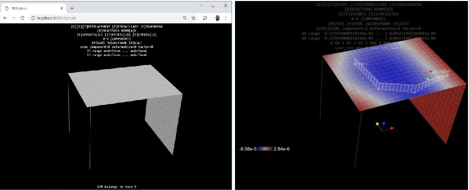
Despite the advantages of a low-level library, this choice implied some restrictions and had some consequences. First, the local rendering approach was necessary. Then, specific operations to make the data readable inside the three.js library environment was needed: for this scope, a parser, written in Python scripting language, was implemented with MED coupling prerequisite capabilities, in order to read .med or .rmed file formats produced by code_aster and salome_meca as meshes and results. It was possible to extract data and project it over the original mesh (Figure 8), even for complex geometries (Figure 9). The final result is a fully functional .med and .hdf5 based 3D engine for mesh and associated fields visualization, with three.js libraries, to be integrated in the generl Civil Works Tool interface.
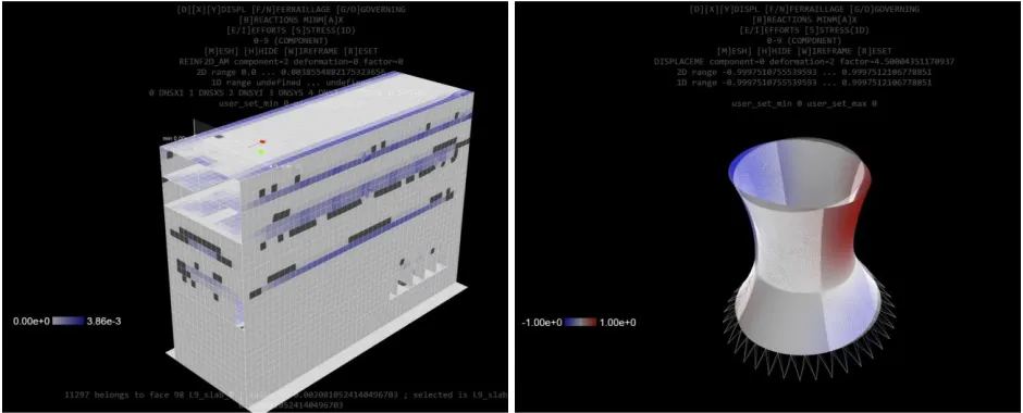
Figure 9. Testing the 3D visualization engine for real cases (left – calculated reinforcement amounts on a real EDF building) or typical nuclear facilities with complex shapes (right).
CONCLUSIONS AND FUTURE DEVELOPMENT
The ongoing EDF’s project (with KOBE and AETHER as partners) for the development of ergonomic tools for reinforcement calculation, described in this paper for the post-processing phase, under KOBE development responsibility, has already shown the great potential that modern visualization technologies can offer and, of course, the engineering content and utility implied in the design optimization phase, which has been revealed to be feasible in this context.
Further improvements are still needed in the visualization phase, as performance losses are encountered for big models and solutions should be investigated for this issue. However, huge steps forward are expected as a challenge for the completion of the optimization process in the design of new structures. Specifically, after the completion of the SLS checks, the implementation of local verifications (concrete nodes, punching shear, strut-and-tie and other regions where reinforcement congestion is an issue) is still expected, while new optimization methodologies should also be explored, including smoothing or redistribution effects or even optimal geometrical properties choice, based both on structural and economic considerations.
REFERENCES
Ahrens, J., Geveci, B., Law, C. (2005), “ParaView: An End-User Tool for Large Data Visualization”,
Visualization Handbook, Elsevier
Ayachit, U. (2015), The ParaView Guide: A Parallel Visualization Application, Kitware
Bresler, B. (1960), “Design criteria for reinforced columns under axial load and biaxial bending.” Journal
of the. American Concrete. Institute, 57(5), 481-490.
Capra, A., Maury J.F. (1978), Calcul automatique du ferraillage optimal des plaques et coques en béton armé, Annales de l’Institut Technique du Bâtiment et des travaux publics, n°367,
EDF (Électricité de France, 1989-2019), ASTER, Finite element code_aster, Analysis of Structures and Thermomechanics for Studies and Research
Fib (2008), Practitioners’ guide to finite element modelling of reinforced concrete structures, Sprint-Digital-Druck, Stuttgart, Germany
Leonhardt F., Moennig A. (1986), C.A. e C.A.P. – Calcolo di progetto e tecniche costruttive, Edizioni di Scienza e Tecnica, Milano, Italia
Pacoste P., Plos M., Johansson M. (2012), Recommendations for finite element analysis for the design of
reinforced concrete slabs, Chalmers, Stockholm, Sweden
Perchat, J (2017). Traité de béton armé selon l'Eurocode 2. Éditions du Moniteur, 3ème édition.
Rombach, G. A. (2011), Finite-element Design of Concrete Structures - Practical problems and their