Flow-Induced Vibration of Nuclear Components :
Future R & D Perspective Derived from the French Experience
Laurent Borsoi
Commissariat/t l'Energie Atomique, CEA - Saclay, DEN / DM2S / SEMT / DYN, F-91191, Gif-Sur-Yvette, France.
ABSTRACT
This paper tries to investigate what could be the future R&D work in flow-induced vibration (FIV) connected with the French nuclear activity. The first introductory part recalls some specificity of nuclear energy, and especially points out how FIV interacts with the design process of nuclear reactors. FIV or FSI (fluid-structure interaction) phenomena are anticipated as much as possible, but it is emphasized that many FIV / FSI issues have been evidenced only by the experience of real conditions, which could be interpreted as a counterpart of their subtlety.
For illustration, the second part of the paper makes use of some cases taken out of the French electro-nuclear project (PWR and FBR) during the two last decades. It is particularly evoked the Superph6nix weir instability, the FIV of control rods and in-core instrumentation, the design of Steam Generator tube bundle. Different aspects are briefly commented : anticipated or not FIV / FSI, involved damage connected with Safety, impelled R&D effort, practical engineering solution and cure, lesson for the future,...
Bearing the previous examples in mind, the third and last part of the paper attempts to elaborate a prospective of the FIV / FSI needs in the future. Two challenges are especially emphasized. Concerning some basic FIV configurations, such as tube bundle in cross flow or slender structure in axial confined flow, the challenge of the next decade is to deeply understand the physical mechanisms that control FSI. The progress in computational fluid dynamic (CFD) should significantly contribute to this fundamental understanding, but experimental tests will always be needed. The feedback of this understanding should impact the way of performing tests and reducing data, and permit to define new, but simple, design rules, like Connors' map, with well identified margins. Special attention must also be focused on two-phase flows given their large use in industry and inherent major difficulty.
An other challenge will be to fully anticipate FIV / FSI problems, if any, when facing new design without any previous experience. For this purpose, general "tool box" computational codes should be developed to be able to carry out rapid applications. One key problem is thus to adopt the good level of modeling since it has already been pointed out the subtlety and sensitivity of some FSI issues. So a severe effort of FIV / FSI classification should be undertaken in that sense, covering among others the birth of instability. In parallel it is noted these two challenges must not mask the other ones, especially related to non-linear dynamics, probabilistic approach, structural mechanics and CFD, treatment of highly coupled problems.
NUCLEAR SPECIFICITY
Are the flow-induced vibration (FIV) or fluid-structure interaction (FSI) problems encountered in nuclear reactors specific ? If yes, for what ? The answer to theses questions is of course varied. As for many industrial equipment, FIV or FSI issues are not of primary concern for engineers in charge of reactor design. It does not mean they ignore this kind of phenomena and their associated consequences, but they do have other priorities in elaborating such complex machines. First of all, a civil nuclear reactor is a thermal machine from which the central focus on the heat transfers that have to be optimized : heat source (core and fuel design, temperature,...), coolant fluids (to extract the thermal power from the core, transport and exchange it), mechanical structures (to support the core, conduct and canalize the fluids, facilitate the heat transfers). This design optimization phase is drastically complicated by the nuclear specificity which adds severe constraints, in particular with Neutronics (moderator,...) and Safety in a general way.
Nuclear Safety
Basically nuclear Safety has three objectives : 1/to ensure normal operation of the facility while restricting radioactive release in the environment, 2/to prevent from incidents or accidents, 3/to limit the consequences of incidents or accidents if any. The principle of defense in depth is to do "all" so that "it" does not occur, but even if "it" occurred, there would be the capability to control the situation (i.e. to control the nuclear reaction, to transfer the residual energy from the fuel, to keep the radioactive elements confined) and to avoid getting a more deteriorated one. Nuclear Safety impacts FIV or FSI at different levels, particularly through, i) the justification of the mechanical behavior of components during normal operation (prevention mode), ii) the introduction in design process of hypothetical events like high intensity earthquakes, pipe or pressure vessel ruptures, explosions, etc. (limitation of consequences).
SMiRT 16, Washington DC, August 2001 Paper # 1460
Complexity
No need to insist on the complexity of a nuclear reactor composed of the main fluid circuits ensuring the heat transfers, and so focusing attention, but also of a lot of auxiliary and secondary components and piping systems required for operating the reactor under normal, incidental or even accidental conditions • regulation and protection systems, engineered safeguard systems, emergency plant cooldown systems, etc.. This complexity makes that even the more standardized reactors may present new FIV / FSI configurations, without any feedback experience under real conditions, during their natural evolution (modified operation mode, up-to-date model, slight change). It is pointless noticing this lack of feedback experience is much greater for a reactor prototype with a completely new design.
FIV / FSI Issues
In short, a nuclear reactor is an extremely complex thermal machine, composed of a vast number of sub-components or systems with very various design, and having to satisfy a very high safety level. FIV or FSI issues are more "suffered" than expected - engineers would prefer they really do not exist ! - and are analyzed at different steps of the plant life :
- during the basic design phase, more for verifying the proposed design thafi for driving it, excluding some well-known and critical cases (e.g. vortex shedding around cylindrical structures),
- during the life of the facility, in a predictive way, following modifications of materials or operating conditions wanted (life extension, increasing of performance,...), or not (deteriorated situation),
- during the life of the facility, following unexpected incidents to attempt to explain them : this is the "famous" feedback experience, the only determining factor ("Juge de Paix") in industry, which sometimes evidences some very subtle FIV / FSI phenomena, absolutely not anticipated nor imagined.
O B J E C T OF THE P A P E R
This paper tries to investigate what could be the R&D effort during the next decade in FIV / FSI domain connected with the French nuclear activity. For this, it makes use of some real cases taken out of the French civil electro-nuclear project. These examples are not treated in depth - it is not the purpose of the paper - but synthesized in perspective : anticipated or not FIV, involved damage connected with Safety, impelled R&D effort, practical engineering solution and cure, lesson for the future, lack of basic knowledge, etc..
The choice of the French electro-nuclear project limits the examples to fast breeder reactors ( F B R " PMnix and Superph6nix) and pressurized water reactors (PWR, 58 units in France). So it is no question to be exhaustive, but just to illustrate some FIV / FSI issues. (Note that PWR are very popular in the world : at the end of 1999, 207 units for a total of 443 were PWR units). This paper is more descriptive than technically detailed. For a technical and more exhaustive overview of FIV progress and prospects, see the reference [ 1 ].
F L O W - I N D U C E D V I B R A T I O N M E C H A N I S M S
Different FIV mechanisms are hereafter shortly reviewed for clarity. They are divided in three classes, based on simple physical considerations, but this partition does not intend to cover all possible FIV mechanisms (see [1 ], [2], [5], [13]).
Structure-Still Fluid Coupling
It deals with the dynamic interaction between a vibrating structure and a still fluid, (i.e. the fluid is at rest if one excepts the oscillatory flow induced by the vibrating structure). The main physical phenomenon involved in such a coupling is added mass due to fluid, and at a less degree, viscous damping especially in case of squeeze film.
Turbulent Excitation
Fluid-Structure Interaction (FSI)
FSI concerns all the dynamic interaction which may occur between a flowing fluid and a moveable mechanical structure. When the structure is linear and elastic, the interaction is expressed in the so-called fluidelastic forces. FSI leads to an exchange of energy between the flow and the structure. In some favorable cases, the non-conservative energy transfer process has a stabilizing effect by providing an additional damping to the vibrating system. But it may act just at the opposite by inducing fluidelastic instability, which results in excessive and dangerous vibrations, only limited (if they are) by the non- linearity of the real system • impact against neighboring structure, structural plasticity, geometrical stiffness, destruction of the fluid organization due to high amplitude motions, etc.. Fluidelastic instability is always associated with the change of the dynamic characteristics of the coupled fluid-structure system with the flow velocity. When the mean flow velocity reaches some critical value, instability occurs, the root cause of which may be various. Roughly speaking, divergence is related to zero-stiffness in the fluid-structure coupled system (see eq.2), flutter to zero-damping (eq.2) or to the mix-up of two eigen- frequencies when the flow,velocity increases (the flow coupling makes two modes, initially separated, converge to the same frequency- one increases while the other decreases -, which produces a exponential "explosion"). More precisely, the expressions "zero-stiffness" or "zero-damping" must be understood in modal terms • zero-generalized-stiffness or damping. By extension, vortex shedding with lock-in phenomenon could also be ranged in FSI class, since it gathers - in opposition to the turbulent class - all the excitations produced by the fluid on the structure which depend on the motion of the structure.
Basic FIV Equation
Just for illustration, one considers the following schematic equation with classical notation •
ms.2(t) + Cs.k(t) + k s . x ( t ) = ft (t) + ffs(2,/(, x) (])
The left side represents the dynamic response of the "dry" structure, with contributions of inertia m s . 2 ( t ) , viscous damping Cs./~(t ) , and stiffness k s . x ( t ) . The right side gathers the action of the fluid on the dry structure, partitioned here into the turbulent forces ft (t)that are structural motion independent, and the fluid-structure forces ffs (2, /(, x) that are structural motion dependent. These last ones are often linearized : ffs (2,/~, x) = - ( m fs. 2 ( 0 + cf s./~(t) + k fs. x(t)) , i.e. into the dynamic standard form. The fluidelastic coefficients for damping Cfs and stiffness k fs generally depend on the mean flow velocity (v). Equation (1) is thus transformed into :
[m s + mfs].2(t) + [c s + Cfs(V)].:k(t) + [ks + kfs(V)].x(t)= ft(t) (2)
The turbulent excitation - right side - is applied on the coupled fluid-structure system - left side -, the dynamic characteristics of which depend on the flow velocity (v). Shortly and schematically, the first item of this section, "Structure- Still Fluid Coupling", is dedicated to the added mass term mfs , the second one, "Turbulent Excitation", to the right term
ft ( t ) , and the third one, "FSI", to the damping and stiffness fluid terms Cfs(V), kfs(V ) .
FIV Related Damage
Flow-induced vibrations, like most of mechanical vibrations, are studied because of the damages or nuisances they can generate • fatigue (low-cycle, elastic), wear (friction, impact-sliding, fretting), noise, flow perturbation, etc.. Some FIV phenomena are detected by a vibratory survey, but most of them are only evidenced through the induced damages. Some damages are so violent and devastating they are soon discovered during the first commissioning tests. But others, like elastic fatigue or wear, may require a long incubation period and so be only detected after a few years of operation. Risk of fatigue is usually estimated from Miner's law, integrating WOhler's curve and cycles counting. But when FIV generated stresses are much smaller than the material endurance limit, fatigue is not a real problem. On the other hand, wear prediction is commonly based on Archard's law, which connects the missing volume per unity of time V to the wear work rate •
T 1
~fn vt dt WR = T " "
I
0
; v = k . W a (3)
THE SUPERPHENIX WEIR INSTABILITY
General
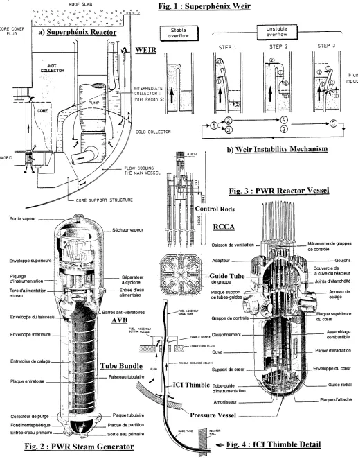
Superph6nix, located at Creys-Malville in France, is a 1300 MWe fast breeder reactor (FBR) of pool type, cooled by liquid sodium. Thin baffles arranged inside the reactor vessel separate sodium into different volumes, so-called collectors. The main collectors are of great capacity like the hot collector at the core outlet or the cold collector at the primary pumps inlets. But others, like the feed or restitution collectors of the main vessel coolant system constitute in fact thin fluid layers given their dimensions (see Fig.la). In October 84, during the first commissioning tests at hot flow conditions, unexpected vibrations of high amplitude were detected by the monitoring vibration general system. Their signature changed with t h e primary flow rate, but exhibited a clear low-frequency component at 0.3 N 0.4 Hertz. The weir shell separating the feed collector from the restitution one of the vessel coolant circuit was particularly affected.
Investigation
CEA/Saclay, in charge of the investigation, soon evidenced a subtle fluidelastic instability phenomenon. In a few weeks, it was successful in proposing a nonlinear analytical model capturing the essential features of the involved Physics, based on a very simplified plane mock-up and first numerical simulations. The FIV phenomenon is roughly schematized on Figure lb. Instead of being regular, the sodium flows over the weir in a discontinuous and pulsated manner, following the lateral motion of the weir shell, itself generated by the pulsating flow, more especially by the "impact" of sodium "clumps" expelled over the weir and dropping onto the free surface of the restitution collector. Thus gravity, as well as the weir shell flexibility which permits a feedback action from the restitution collector to the feed one, produce such a self-excited phenomenon, much more complicated in reality since involving different fluid-structure coupled modes, particularly of sloshing.
The derived model considers, i) a negative flow rate source over the weir • - q w (t, 0 ) = - k ~ h(t, 0)3/2, with h the fluid thickness passing over the weir (h _> 0) at the azimuthal angle 0, g the gravity and k a constant related to the weir geometry, ii) a positive flow rate source at the restitution collector: qr ( t , 0 ) = +q w (t - x, 0) , with z a time delay due to the sodium drop, and a pressure source : p(Az) = 9 g Az + qr Vf / e r , located at the elevation Az under the free surface, with Vf the sodium impact velocity and e r the collector width. These different sources were injected as excitation of the coupled fluid-structure system of both collectors, the response of which was calculated by modal synthesis.
In a first step, the linearized equations have permitted to build up a stability map in the 2-D space, steady flow rate versus drop height. It appeared two types of instability could occur :
1/flutter instability by frequency mix-up of two sloshing modes of feed and restitution collectors coupled through the weir shell (low frequency modes depending on the azimuthal index),
2/flutter instability by negative damping of weir shell modes (for higher frequencies).
In a second step, nonlinear modal calculations have been performed to determine the amplitude of limit cycles for operating conditions situated inside linearly unstable domains. (See [3] for details).
Cure And lesson
In a general way, the model and deduced stability map were confirmed by experiments carried out with three analytical mock-ups (the plane one above evoked and two cylindrical mock-ups, 1/12 and 1/4 scaled, studied at CEA and EDF), and by investigations performed on site with Superph6nix reactor. The instability observed during the commissioning tests was of the first type. The deep understanding of the physical phenomena involved in such an instability allowed to predict with a very high confidence level the flow conditions of the vessel coolant system which do not produce instability. Moreover it was possible to reach these safe operating conditions without any significant change in design, but just by properly adjusting the flow rate of the vessel coolant circuit through a simple additional pressure drop at fuel bottom. This small and low-cost modification was without any consequence on the reactor performance and also on the planed schedule for starting commercial operation.
F L O W - I N D U C E D V I B R A T I O N OF TUBE B U N D L E IN STEAM G E N E R A T O R
General
In PWR, steam generators (SG) ensure the heat transfer from the primary circuit to the secondary one (about 1 GW per SG). The pressurized primary water, heated by the nuclear reaction (155 bar, 320°C), circulates inside thousands of U-tubes (inverted U) of about 20 m length, 20 mm diameter and 1ram thickness. On contact with tubes, the up-flow secondary water is heated and vaporized (60 bar, 280°C). Then the produced steam passes through moisture separators for finally being injected into turbine generators. Primary circuit boundary constitutes the second containment barrier and so must be perfectly watertight for Safety reasons. But 80% of this barrier is made of the heat exchange area of SG tubes, which so are particularly watched. Tubes may be subjected to potential FIV since exposed to the secondary flow, which is transverse and single-phase at the bundle bottom, then axial and two-phase along the tubes, and finally transverse and two-phase (85% steam-water mixture) at the top in the U-bends area. Tubes support plates, regularly spaced, strongly restrain the tubes along their straight part. In the U-bends region, the less supported section and so the most critical, anti-vibration bars (AVB) are inserted between tubes to ensure lateral support. (See Fig.2).
Connors' Model
Contrary to the Superph6nix weir whose design is unique, heat exchanger with tube bundle is a common industrial equipment. Since the end of the 50's, it was known such tubes array could become unstable when subjected to severe cross flow. Under the pressure of the nuclear industry, with its high Safety requirement and enormous cost of plant shutdowns and repairs, numerous experimental and theoretical studies became to be intensively performed in the 70's in order to understand, model, predict, avoid,... Complexity of the involved phenomena has been underestimated, and 30 years later, the problem is largely still open although incontestable progresses have been made (e.g. see [4]).
Early from 1970, Connors from Westinghouse proposed a model for the instability of tubes array in cross flow. His model resulted from experiments carried out with a rigid tubes range subjected to air flow. By statically displacing a tube in the flow direction (x), he detected and measured a force induced on the neighbor tube along the perpendicular direction (y); and reciprocally by displacing a tube along y, he measured the force induced on the adjacent tube along x. Then introducing these static coupling forces into the dynamic system composed of the two quasi-identical tubes, he obtained the variation of the dynamic characteristics of the coupled system with the flow velocity V. More precisely the modal damping decreases when V increases. At the critical velocity Vc, the system becomes unstable by zero-damping. In a dimensionless form :
/2x.¢0"m
Vc = K. - - - or Vrc = K. x/A
f0.D ~ ~ f l D 2 , r (4)
with D, m, f0, ~0, respectively the diameter, mass (per length), frequency and damping ratio of the tube for V=0, Of the fluid density, K the "Connors' Constant", A r the reduced mass-damping parameter (Scruton number).
Other Models
In most cases, the experimental campaigns carried out for determining the critical velocity of tubes array for different configurations (structure and flow conditions) have also permitted to determine, on a case-by-case basis, the turbulent flow excitation. Attempts have been made to reduce all the rough available data under a dimensionless form, in order to build up an envelope dimensionless turbulent spectrum for design purpose ([1], [2], [13],...). Other relevant information have also been extracted from these tests, when possible, such as the flow velocity distribution in U-bends area.
Fluidelastic Coefficients
The last decade has been marked by significant progresses in handling FSI effects in tubes array. Connors' approach is still used in industry, but a R&D trend consists in more precisely measuring the fluidelastic forces in the whole range of flow velocity., sub-critical flow V< Vc, and even now over-critical flow V_> V c with the help of active control (e.g. see [ 11 ]). The fluidelastic coefficients that are to be identified are the added mass mrs, the damping term Cfs and the stiffness one k fs, see eq. (2). In general the added mass does not depend on the flow velocity and so is easier to determine. At the opposite, the damping and stiffness terms are flow velocity dependent - it is the reason for instability - and require relevant methods for identification, that may be classified into direct method - the tube motion is imposed and the FSI forces directly measured - or indirect one - the FSI forces are deduced from the tubes response -. Direct methods are implemented with difficulty given the bad signal-noise ratio. On the other hand indirect methods require advanced identification techniques as the turbulent excitation is generally unknown and the response of flexible tubes array exhibits close highly coupled modes [4]. Finally the global strategy concerning fluidelastic coefficients could be resumed as follows : 1) experimental identification from analytical mock-ups, 2) dimensionless reduction, 3) integration of reduced coefficients in codes to calculate real situations.
Current Situation
The design justification is always made using eq. (4) with relevant questions about damping and Connors' constant. Damping for two-phase flow of "zero-velocity" formally has no meaning and is debatable [10]. On the other hand Connors' constant is taken in a conservative way. The result is that stability is ensured but not with a well identified and quantified margin. Consequently the change of the dynamic characteristics with the distance to instability is not strictly controlled. Moreover the incidents that have happened in different plants, notably at Indian Point (1988), North Anna (1990) and Mihama (1991), have surprised although elucidated in great part after.
According to a more physical point of view, it has to be noted the following items. 1) The Physics of the "two-phase turbulence" is not apprehended. Its characterization in term of envelope loading spectrum applied on the tubes is not satisfactory, contrary to the single-phase case. 2 ) T h e interaction of a two-phase flow with a structure, even an elementary one (single tube), is not understood, especially about damping greater in two-phase flow than in single-phase. 3) In a general way, the Physics of instability in tubes array is not captured in single-phase flow, even less in two-phase flow. 4) Roughly speaking, fluidelastic coefficients are sort of "ignorance coefficients"; their prediction as well as their reduction are not satisfactory although understood in a qualitative way. 5) Wear by impact (at the contact tube / AVB ) is not well represented by the classical wear approach of work rate and Archard's law - see eq.(3).
ROD CLUSTER C O N T R O L ASSEMBLY (RCCA)
General
U n d e r - C a r d W e a r
In 1986, a highly abnormal silver activity was detected in the primary system of a French 900 MWe PWR, the origin of which was a punctured RCCA rod. The RCCA was in its 4th cycle and had been in the extracted position most of the time. The investigations soon evidenced a generalized wear vibration phenomenon, named under-card wear, the importance of which had been previously underestimated as attention was entirely focused on axial wear due to RCCA stepping motion. Rod wear is acceptable as long it does not compromise the efficiency and operability of the RCCA during stepping and shutdown. It becomes unacceptable when it reduces the rod structural stiffness too much and thus induces a risk of rod rupture, which could stop the RCCA from dropping. In order to face this problem, French nuclear partners, EDF, Framatome and CEA, launched different actions that cannot be related here in detail; briefly : 1) immediately adopted disposals to can operate reactors with rod wear : smoothing the axial wear distribution by shifting the position of the parked RCCA, periodic survey of RCCA by eddy current testing and ultrasonic examination, systematic RCCA replacement based on a rejection criteria; 2) material study for increasing the cladding wear resistance by appropriate surface treatments and coatings; 3) initiation of various R&D actions to understand, model, predict, avoid,... (See [6], [7]).
Concerning the point 3), difficulty has clearly been underestimated. A first hydraulic mock-up (full-scale, full-flow, cold testing facility involving real components) was soon erected and confirmed that control rods were subjected to FIV. Consequently the logical approach that dominated at the end of the 80's for handling vibration-wear problem was followed. That is : a) identification of hydraulic sources; b) quantification of the associated excitations; c) nonlinear (gap) time history calculation of RCCA vibrations given the previous excitations; d) deduction of the wear work rate at the different card elevations, eq.(3); e) experimental determination of the wear coefficient in wear-machine; f) estimate of worn material volumes from Archard's law, eq.(3).
Cure And Lesson
This analytical approach, although it has produced some interesting results, did not succeed in satisfactorily explaining rod wear obtained in reactor : weir spatial distribution, rods discrimination according to their location in the spider, wear kinetics, etc.. Moreover examinations made in 97 have shown the wear profiles of rods extracted from reactor noticeably differed from the ones obtained in simulators (at a microscopic scale). This clearly indicated the real wear mechanisms were poorly captured and reproduced in laboratory machines. In defense of this general statement, it should be noted the under- card rod wear is a formidably complex problem given the RCCA geometry and their erratic contact points with the guide systems, the flow distributions and FSI mechanisms, the physico-chemical environment and other parameters not still fully identified which make certain reactors more "wearing" than other ones. Finally it has to be mentioned the under-card wear, even if not satisfactorily understood, has been solved by introducing in reactors nitrided control rods that are impossible to wear. So the material solution has "won" for the moment.
IN-CORE INSTRUMENTATION (ICI)
General
In PWR, neutron detectors are inserted inside the fuel assemblies by moving into thimble guide tubes that penetrate into the vessel bottom head from the in-core instrumentation room. ICI thimble guide tubes are long (~ 15 m), flexible, of typically 7.5 mm diameter and 1 mm thickness, and are themselves restrained by guide tubes along their whole length. The leakage of a thimble was detected at Paluel, first-off 1300 MWe in France, eight months after starting. The investigations soon revealed numerous wear traces on most thimbles at different locations (vessel penetration, fuel assembly lower nozzle,...). Wear was attributed to FIV phenomena, which was rapidly confirmed by an hydraulic mock-up. A small pressure drop between the two ends of the instrumentation thimble guide (inside the vessel) created an annular axial flow surrounding the thimble of velocity up to 10m/s. Such a configuration may be favorable to severe FSI effects [8]. A particularly suspected region was the outlet conduct of the thimble guide just under the lower end of the fuel assembly. The studies that have been performed [9] confirmed previous results related to advanced gas reactor (AGR), that is the extreme sensibility of diffuser angle on FIV in confined axial flow. In the present case, a 15 ° (hal0 angle generated excessive vibrations, while a squared end conduct (0 ° angle) significantly reduced them, all the more as it was provided with radial slits that "broke" flow recirculation. But FIV analysis was greatly complicated by the contact conditions of the thimble inside the guide which changed on a case-by-case basis given the thimble flexibility. (See Figure 4).
Cure
reactor confirmed the validity of such a design, which a priori was not so obvious as reduced gap could intensify FSI effect through confining.
OTHER EXAMPLES
Due to the space limitation, the other examples are not developed but are just quoted for memory. The list is not exhaustive.
Flow-Induced Vibration Of Piping System Due To Turbulence
Basically a piping component that induces a sudden change either in the cross-area or the direction of the mean flow can be considered as a flow singularity which generates random fluctuations of pressure and mass flow. These fluctuations produce random vibrations, either directly by the turbulence taking place in a restricted zone downstream from the singularity or principally, but indirectly, by the low frequency acoustic noise that is generated in the circuit (see [5], [13]). The piping vibrations may induce fatigue damage, particularly at the nozzle of small branches connected to big ones and ruptures are sometimes observed. The issue covers the quantification of the different acoustical sources as well as the evaluation of the structural response which is very sensitive to frequency coincidence and various uncertainty (like the local nozzle stiffness).
Seismic Core Modeling
For obvious safety reasons, seismic loading has to be taken into account in reactor design. Seismic modeling of PWR and FBR reactors has been the object of various developments. To treat the fluid-structure coupling was particularly of primary importance for Superph6nix given the large flexible shells and the presence of sodium. Concerning more especially the seismic modeling of cores, different difficulties may be noted : i) the seismic excitation transmitted to the core by the supporting structures must be correctly evaluated, ii) the core is made of different assemblies (fuel assembly, neutronic protection) generally non linear and impacting each others, iii) accounting for the fluid must be compatible with the core modeling which is obviously simplified. Numerous experimental tests have been performed on shaking table to validate the seismic core modeling, notably the ones based on homogenization methods. The frequency shift due to the presence of fluid may reach -30%, which illustrates the importance of added masses.
Fluid damping may also be important. Experiments have shown that PWR fuel assembly is strongly damped by the primary axial flow with possible ratios over 20-~25%. FSI is also involved in squeeze fluid film due to impact.
Shafts Of Primary Pumps
The shaft of Superph6nix primary pumps is set inside a concentric cylindrical sleeve in order to avoid gas entrainment from the argon/sodium free level. This design leads to the specific FSI configuration of a rotor immersed in a moderately confined flow, which is quite different from the usual case of hydrostatic or hydrodynamic bearings. Such a configuration has been extensively (experimentally and theoretically) studied at CEA/Saclay, with main concerns about instability and the fluidelastic forces (stiffness and gyroscopic terms proportional to the added mass) that are developed (taking into account flow friction or not). (See [2], [13]).
FUTURE R&D W O R K
Tubes Array In Cross-Flow
Given the previous statement, a challenging task should be to deeply understand the basic Physics that governs FSI, especially the fluidelastic instability, in tubes array in cross-flow. For this purpose, recent and future progress in computational fluid dynamics (CFD) should be an appreciable aid. CFD methods are various and the object of a lot of numerical developments. So the first step consists in choosing a method, an existing one or one to be developed, that is a priori a "good" candidate (see next section : FSI Classification). Then this method has to be tested and evaluated by simulating basic FSI experiments on tubes array in single-phase cross-flow that could be so-called "crucial": Connors' range, one single flexible tube,... In this context, new FSI experiments that are currently missing for a basic comprehension should also be completed and simulated (e.g. 1, then 2,..., then N flexible tubes in a rigid forest to catch on the tubes mutual interaction process). Numerical approach, once closely validated by experimental results and so made reliable, permit of new experiments impossible to carry out into practice and fine examinations of fluid fields of pressure, velocity, vortex,... This should permit to identify the pertinent physical parameters that control FSI and to establish physical models that are predictive (involving, if relevant, these famous "ignorance" fluidelastic coefficients that are Cfs et k fs ).
(with respect to single-phase flow) since the similitude laws are not fully apprehended. So progress passes through a deeper understanding of the Physics based on analytical experiments, especially to appreciate the influence of mixture topology (void fraction, granularometry, regime,...) on induced vibrations (notably to understand the two-phase damping). As for the single-phase case, numerical approach may be an appreciable aid, but it is suspected much time will be needed just for modeling the elementary interaction of a single tube with fluid.
Basic FSI Configuration
Tubes array in cross-flow is one example of basic FSI configuration. Others exist in reactor or nuclear facility : slender tube in axial flow (isolated tube or arranged in array, flow confined or not, etc.), shell or plate system in parallel flow, flexible structure in typical flow singularity like abrupt widening or narrowing, shell for deviating flow, bluffbody of regular geometry in cross-flow, etc.. These configurations are found, among other components, in fuel assembly, regulation and control system, internal equipment, piping system. Some of them have been analyzed since the 70's and are well understood (e.g. flexible pipe conveying fluid). But most of them have been studied on a case-by-case basis just after incidents have occurred, and so are far from being fully apprehended (see ICI ex.). First the question is to clearly identify some very generic situations : slender structure in axial-confined flow whose instability strongly depends on boundary conditions [8] or flexible structure in recirculation flow due to singularity seems good candidates. Then, as for tubes array in cross-flow, the challenge is to deeply understand the involved Physics with also the support of numerical simulations (and new experimental tests).
To capture the Physics - root cause of interaction and instability - is one key step, but not the f'lnal goal. FSI complex phenomena, once dominated, must be the object of simplified rules, tabulated or integrated in an appropriate form for engineering practice, like Connors' map, but with margins clearly identified and quantified. The ultimate goal would be to reach dimensionless reduction that would satisfy "any structure, any flow", with all the relevant and appropriate H-terms... All theses effort of comprehension / reduction of FSI phenomena must go in parallel with a severe effort of classification.
FSI Classification
An effort of classification must be done about the physical mechanisms that pilot the interaction, particularly the ones
which give birth to instability. In other words, the question is to know if the interaction is "fine" or not. Classification is of course strongly connected with the profound understanding of the Physics that governs FSI, and is notably essential to adapt the numerical modeling to the treated problem. Indeed numerical model must not be too refined, and so unnecessarily expensive and tractable with difficulty, but it must not be too crude either, which risks to deform the interaction and even to cancel the instability birth. For instance, a "by-hand" calculation is almost sufficient to explain hosepipe instability. In the same way, it is suspected that some FSI problems should be understood and explained through very simplified modeling. At the opposite, other ones should require sophisticated and refined models to be captured, especially for the instability triggering in shear layer. But all graduation must exist between these two extreme cases. Classification should also deal with the post-unstable behavior since instability is sometimes followed by a return to stability.
FSI modeling involves, i) the solution of the Navier-Stokes equations (NS) with moving boundary conditions, ii) the computation of the structural response due to the fluid interface loading, and iii) the mutual interaction process at interface. These three items - fluid, structure, interaction - have been here artificially separated for clarity, but they should be solved all together at the same time for a rigorous FSI modeling; (nevertheless a lot of time history resolutions may support step-by- step separated solutions for fluid and structure with output-input chaining). Generally the structural part does not set serious problems compared to the fluid one. To solve the NS equations with fixed boundary conditions is always an active research area, especially at practical Reynolds numbers (finite-elements method, finite-volumes, large eddy simulation (LES), vortex- in-cell method,...). Of course taking into account moving boundary conditions increases difficulty, and is all the more difficult as a precise solution is searched at the interface, i.e. in the region of shear layers where fluid modeling and response is the more delicate and complicated. The arbitrary Lagrangian-Eulerian (ALE) method appears very attractive because of its formulation that involves a moving mesh following the structural displacement and so facilitates the interface modeling. Other attractive methods are based on fixed but transmissible or "breathing" frontiers for the fluid mesh, the conditions of which depend on the structural response. Large displacement applications with such methods seem a priori difficult (due to the wall law) but must be studied. It should also be mentioned all the integral formulation whose purpose is, roughly speaking, to totally report the fluid contribution on the structural motion or to significantly reduce the fluid modeling with respect to the structural one (number of degrees of freedom of the same magnitude for fluid and structure). Of course this list is not exhaustive, and a lot of other methods are "good candidates" for handling FSI.
Turbulent Excitation
The action of turbulent flow on structure must be quantified in order to calculate the structural response. This action depends on the turbulence (in a wide sense) developed in the fluid, but also on the spatiotemporal filter the structure is forming. Based on experiments and taking profit from some assumptions (homogeneity, correlation lengths,...), this quantification is now satisfactory in some cases • basic singularity in piping system, tubes array in single-phase flow, slender tubular structure in axial flow,... But in most cases, this quantification is not acceptable or does not exist at all. Given the recent progress in CFD for simulating/modeling turbulence, the idea is quite natural to try to compute the turbulent excitation instead of measuring it as it has been done for 30 years. It is all the more attractive as the problem in purely fluid for this kind of application (with rigid structural walls, see eq. 2).
For example, LES method has been recently used with success to calculate the load turbulent spectrum that is exerted on a tube by a single-phase annular axial flow [12]. But the work for this kind of application must be amplified and consolidated. The final goal is to compute turbulent forces that are applied on structure (per unity of length or surface), but in a reliable and robust way and without resorting to any experimental data. Theses calculations should permit either to determine envelope spectra which are currently missing for design of some generic configurations, or to treat particular geometry and situation.
Just as for FSI classification, a special attention shall be focused on the different methods for simulating/modeling turbulence (DNS, LES, k-e, 2 nd order, shear layer modeling...) in view of their resulting action on the structure (especially to take benefit from the structural filter as well as the low frequency structural response which often pilots the involved damage).
FIV / FSI "Tool Box" Code
An other challenge will be to fully anticipate FIV / FSI problems, if any, when facing new reactor design without any previous experience (see Superph6nix example). For this purpose one should have some "tool box" code for FIV / FSI general modeling which would permit rapid applications. As already stated, one key problem is thus to adopt the good level of modeling and this passes through the severe, but indispensable, effort of classification that has been pointed out for FSI as well as for turbulence. The "tool box" expression must not be a source of confusion. It just does mean the initial FIV or FSI problem must be modeled in the most appropriate way, neither too ref'aned nor too crude. This research of optimization does not always convince people given the Continuous growth of computer power, and indeed one must not take the wrong era I But generally the appropriate degree of modeling goes with an increase of the physical understanding, the possibility of quick applications, which is essential during a design phase where the parameters are not fixed, and a better ability for taking into account randomness and uncertainty.
Mock-ups will be still used in the future to analyze FIV / FSI issues, but in a different and limited way with respect to the past. Mock-ups should be more analytical and guided by the confrontation with computation, and so less expensive and not for a purely rough design qualification, although this way of doing will be still inevitable in the next future.
Efficient Prediction of FIV Involved Damage
Most of structures are nonlinear and uncertain (i.e. not very accurately known) for various reasons : presence of small gaps, contact stiffness, localized plasticity, hysteresis, local effect, membrane effect,... Moreover they are subjected to FIV excitations that are either random per nature (turbulence) or uncertain (turbulence, fluidelastic forces). The FSI coupling process, or others like the parametric excitations, increase the general uncertainty attached to the structural response. So in most cases the induced vibrations are nonlinear, random, non gaussian and uncertain. To know how to calculate, then characterize, the response process in term of the involved damage is still an open challenge although not often pointed out. Realistic computations of nonlinear vibrations, with comparison to experimental data, have made significant progress in the 80's, notably for the structures with gaps. But some questions need to be visited again in relation with specific items (e.g. impact with squeeze fluid), the uncertainty above evoked and also the better knowledge and control of involved damages.
For elastic fatigue, it deals with the very high cycle WOhler's curves, the new criteria (multi-stress state, energetic approach,...) that have appeared for two decades, as well as the cycles counting. For wear-vibration, it deals with the identification and statistics of the pertinent parameters that really pilot the damage since the work rate approach, illustrated by equation (3), is suspected to be not so universal as it was believed. This observation is as more reinforced as the damage is not purely mechanical but coupled with the physical-chemistry (see RCCA example).
confidence (see above), ii) to have at one's disposal relevant information about the damage quantification (worn depth,...). This should permit, through Bayesian techniques, to update crucial basic data that are currently missing or too uncertain such as the real turbulent sources or the precise structural geometry (gap size,...). The interest lies in a better knowledge for the future reactors, but also and mainly in an increase of reliability for the predictive analyses with the current reactors, which could impact the monitoring and maintenance operations and the issues about the life extension of the plants.
CONCLUSION
In a general way, but derived from the French experience, this paper has tried to investigate what could be the R&D work about flow-induced vibration or fluid-structure interaction in the next decade connected with the nuclear activity. Of course projection in the furore is always a very uncertain and limited exercise, and no need to insist on the fragility of the opinions that have been emitted.
In the past, the only way to handle FIV / FSI issues was to carry out experiments, generally as closed as possible of "reality". Then analytical mock-ups were more and more used for a better understanding and the proposal of predictive models when possible. May be in a far future FIV / FSI issues will be entirely treated by computations. But this time is not still arrived, and a lot of CFD calculations will remain out of reach in the next decade for industrial applications (high Reynolds number, two-phase flow, complex geometry,...). Nevertheless the CFD support should be an appreciable aid for FIV / FSI issues, and this in three complementary ways : a) to compute complex and specific situations, b) to help for a deep understanding of the involved Physics, c) to permit the emergence of new simplified rules and/or dimensionless data for design. First, FIV / FSI computations must be consolidated and made reliable through the confrontation with basic experiments. Then they will be performed for the different purposes evoked : specific configurations of turbulence and FSI, fimdamental understanding of the Physics (basic FSI configurations, FSI classification, identification of relevant dimensionless parameters for reduction), creation of simplified rules and envelope data for design (for FSI and turbulence).
The "dream" of an universal "FIV / FSI tool box code" for rapid applications when confronted to new reactor design, without any feedback experience, has also be noted. This "tool box" concept must be in coherence with FSI classification and at a less degree with turbulence classification. It has also been pointed out that a better knowledge of FIV induced damages (fatigue, wear,...) is essential to cope with FIV issues, and this is as more crucial as the damage has a long period of incubation, and is not purely mechanical but strongly coupled with physico-chemical phenomena. At last it is clear that FIV / FSI issues should integrate all kind of progress made in connected fields such as non-linear dynamics, probabilistic approach, structural mechanics and CFD, treatment of highly coupled problems, experimental processing, etc..
REFERENCES
[ 1 ] D.S Weaver, S.Ziada, M.K.Au-Yang, S.S.Chen, M.P.Pa'fdoussis, M.J.Pettigrew: "Flow-Induced Vibrations in Power and Process Plant Components - Progress and Prospects". Journal of Pressure Vessel Technology, August 2000, Vo1.122. [2] F.Axisa: "Flow-Induced Vibration of Nuclear System Components", in Technology for the 90's, ASME, 93. [3] S.Aita, R.J.Gibert: "Fluidelastic instability in a flexible weir : a theoretical model. ASME, PVP vol. 104, 1986.
[4] S. Granger, E.de Langre: "Vibrations sous 6coulements et instabilit6s dynamiques des faisceaux de tubes des 6changeurs de chaleur". Revue Frangaise de M6canique, (1) : 38-47, 1995.
[5] R.J.Gibert: "Vibrations des structures. Interactions avec les fluides. Sources d'excitation al6atoires". Paris. Editions Eyrolles, 1988.
[6] L.Borsoi, Ch.Canteneur, G.Barbe :"Experimental and computational investigation into vibration wear of control rods in french PWRs". 4 th International Symposium on FSI, AE, FIV & Noise (ASME); Nov. 1997; Dallas, Texas.
[7] M.Zbinden, M.Dragon-Louiset : "Usure induite par vibrations sous 6coulement : le cas des grappes de commande des r6acteurs/l eau pressuris6e. Des 6redes th6oriques aux applications industrielles". Mec. Ind. (2000) 1, 581-592.
[8] E.de Langre, S. Granger: "Couplage structure-6coulement axial confin6". Rev.Frangaise de M6canique, (1): 49-55, 1995. [9] D.J.Gorman, J.L.Godon, J.Planchard: "Analytical and experimental study of the vibratory response of a flexible robe subjected to external annular flow part away along its length". Int.Conf. on FIV (BHRA), May 1987, England.
[10] F.Baj, PhD thesis (Paris VI, 1998) • "Amortissement et instabilit6 fluide-61astique d'un faisceau de tubes sous 6coulement diphasique".
[11] S.Caillaud, PhD thesis (Paris VI, 1999) :"Excitation forc6e et contr61e actif pour la mesure des forces fluide- 61astiques".
[ 12] M.Marti Moreno, PhD thesis (Paris VI, 2000) : "Simulation num6rique des efforts al6atoires exerc6s par un 6coulement turbulent annulaire".
C O R E C O V E R PLUG
DIAGRID
'Sortie vapeur
ROOF SLAB
o o ~ o o o G c o o o 1 1 o • ."; r, 0 o o o o
a) S u p e r p h 6 n i x R e a c t o r
-HOT
: ,COLLEC'rOR :
. .
Enveloppe sup6rieure
C O R E S U P P O R T S T R U C T U R E
S6cheur vapeur
P i q u a g e t ' ~ S6parateur
d'instrulentatio ~ - - ' .; ii i._~ ~ cyclone Tore d'ahmentatlon . . . . Entr6e d'eau
en eau ~ 1 ~ alimentaire
_ Barres anti-vibratoires
Enveloppe du faisceau --i AVB
Enveloppe inf6rieure
Fig. 1 • S u p e r p h 6 n i x W e i r
Stable 1 overflow
W E I R
INTERMEDIATE C O L L E C T O R • Inter Redan SI:
COLD C O L L E C T O R
S T E P I
F L O W COOLING THE MAIN V E S S E L
Entretoise de calage
Plaque entretoise
Unstable overflow
STEP 2
®
L | i
®
qlb) Weir Instabili .ty M e c h a n i s m
STEP 3
Fig. 3 " P W R R e a c t o r V e s s e l
. Adapteur
, ~ ; / ~ . ~ ~ - - - G u i d e Tube-!
~ / ~ ' I ~
de grappe~ ~ ~ Plaque support
de tubes-guides,,
,.~.~
FUEL ASSEMBLY
GUIDE TUBE
Grappe de contrBle -
~UEL ASSEMBLY
BOTTOM NOZZLE
. . . ,o, onn meot--
ITS__
THIMBLE GUIDANCE COLUMNDove_
T u b e B u n d l e ~,.0w support de ceeur _
tubulaire
_ _ Faisceau
~
J ~ - I C I Thimble Tube-guide ~
dinstrumentationAmortisseur
Pressure Vessel
Collecteur de purge ~ ~-_i ... ~ , ~ Plaque tubulaire !
Fond h6misph6rique Plaque de partition
REACTOR
Entr6e d'eau primaire ~ Sortie eau primaire WALL
:,,~;". 2 • P W R S t e a m G e n e r a t o r ~-- Fi~. 4 • I C I T h i m b l e D e t a i l
Fluid impact
M6canisme de grappes de contrSle
Goujons Couvercle de - la cuve du r6acteur
_ Joints d'6tanchdit6
~
____ Anneau de
calagePlaque sup6rieure du cceur
Assemblage combustible
Panier d'irradiation
Enveloppe du coeur
Guide radial