University of Windsor University of Windsor
Scholarship at UWindsor
Scholarship at UWindsor
Electronic Theses and Dissertations Theses, Dissertations, and Major Papers
1-1-2007
Implementing IPsec using the Five-layer security framework and
Implementing IPsec using the Five-layer security framework and
FPGAs.
FPGAs.
James Wiebe
University of Windsor
Follow this and additional works at: https://scholar.uwindsor.ca/etd
Recommended Citation Recommended Citation
Wiebe, James, "Implementing IPsec using the Five-layer security framework and FPGAs." (2007). Electronic Theses and Dissertations. 6985.
https://scholar.uwindsor.ca/etd/6985
Implementing IPsec using the Five-Layer Security Framework and FPGAs
by
James Wiebe
A Thesis
Submitted to the Faculty of Graduate Studies through Electrical and Computer Engineering in Partial Fulfillment o f the Requirements for the Degree of Master of Applied Science at the
University o f Windsor
Windsor, Ontario, Canada
2007
Library and Archives Canada
Bibliotheque et Archives Canada Published Heritage
Branch
395 W ellington Street Ottawa ON K1A 0N4 Canada
Your file Votre reference ISBN: 978-0-494-35010-2 Our file Notre reference ISBN: 978-0-494-35010-2 Direction du
Patrimoine de I'edition
395, rue W ellington Ottawa ON K1A 0N4 Canada
NOTICE:
The author has granted a non exclusive license allowing Library and Archives Canada to reproduce, publish, archive, preserve, conserve, communicate to the public by
telecommunication or on the Internet, loan, distribute and sell theses
worldwide, for commercial or non commercial purposes, in microform, paper, electronic and/or any other formats.
AVIS:
L'auteur a accorde une licence non exclusive permettant a la Bibliotheque et Archives Canada de reproduire, publier, archiver,
sauvegarder, conserver, transmettre au public par telecommunication ou par I'lnternet, preter, distribuer et vendre des theses partout dans le monde, a des fins commerciales ou autres, sur support microforme, papier, electronique et/ou autres formats.
The author retains copyright ownership and moral rights in this thesis. Neither the thesis nor substantial extracts from it may be printed or otherwise reproduced without the author's permission.
L'auteur conserve la propriete du droit d'auteur et des droits moraux qui protege cette these. Ni la these ni des extraits substantiels de celle-ci ne doivent etre imprimes ou autrement reproduits sans son autorisation.
In compliance with the Canadian Privacy Act some supporting forms may have been removed from this thesis.
While these forms may be included in the document page count,
their removal does not represent any loss of content from the
Conformement a la loi canadienne sur la protection de la vie privee, quelques formulaires secondaires ont ete enleves de cette these.
ABSTRACT
( A VHDL implementation o f 128-bit AES on a Xilinx Virtex-4 FPGA (lowest
speed grade) and ML403 development board is developed from a Verilog design that
adheres to the FIPS-197 standard, adding innovative features: automatic start of
transform, CBC mode, key permutation value readout and store, and output of each
intermediate state value. Core processing rate achieves 640 Mbps; 27 Mbps is achieved in
practice, via peripheral register access. A non-linear, cryptographically secure LFSR-
CASR pseudo-random number generator with a cycle length of 280-243-237+ l is
translated into C and C++ from Verilog and evaluated. A C design and implementation of
IPsec, based on the Five-layer security framework, using these primitives, is presented.
The rate o f IPsec packet processing achieved is 2 Mbps, determined by direct pulse
measurement. A PC-based GUI drives the IPsec implementation and serves it policies,
with a framework for flexibly choosing services, mechanisms and primitives using the
SMIB.
Index Terms: IPsec, Virtex-4, FPGA, AES, pseudo-random number generator,
DEDICATION
To my mother, for a staggering amount o f love, that is so great, that it is as
ACKNOWLEDGEMENTS
I would like to thank the members of my thesis committee, Dr. Shervin Erfani,
Dr. Huapeng Wu, and Dr. Arunita Jaekel, for their support, advice and encouragement
and patience in arranging the times of my seminars! My advisor, Dr. Erfani, also
provided funding and printed and read all of my published and presented work done
during the time o f my Master’s project work; as well, he helped me bum my seminar
CDs on a last-minute basis. Dr. Wu also kindly printed a copy of my thesis for me.
I gratefully acknowledge the assistance of the department technologists, Mr.
Frank Cicchello and Mr. Don Tersigni, for support in ordering and providing equipment
and tools, and setting up presentations. The University of Windsor ECE (Electrical and
Computer Engineering) department secretary, Andria Turner, was absolutely wonderful
in chairing my defence, in providing other support during the time of my defence that I
needed due to an extensive power failure that occurred that day, and in providing much
other support during the time of my Master’s work. Also, Dr. Roberto Muscedere
provided equipment. Liviu Danaila, and George Granata, the FAEs (Field Applications
Engineers) employed by the ML403 development board vendor, Nu Horizons, were
invaluable. Liviu was the local FAE, and helped me considerably. Jennie, the Nu
Horizons sales representative, made sure that I received the ML403 board by keeping
track of the order. The following Xilinx technical support personnel were helpful with
“webcases”: Jonney Zhao, James Broadhead, Enda Behan, Yolanda Xu, Ricky Su and
Zhaojin (“Michael”) Ye. “KJ” on the comp.arch.fpga Usenet “newsgroup” helped me set
simulation timing values so that the “post-map” simulation of my AES encryptor
succeeded.
Some o f my initial training was done on the Xilinx “Microblaze” boards using
Xilinx training “lab” exercises from Xilinx and also as hosted by Dr. Paul Chow on his
website at the University of Toronto [UTXILT]. The various tutorial documents provided
by Xilinx were very useful - see the “Books, General Papers and other Resources” sub
section in the References section: the reference codes beginning with “XIL”, particularly
Thanks are due to my fellow students, Nima Bayan, Fang Chen, Amir
Yazdanshenas, Raymond Lee, Kevin Banovic, Ian Anderson, Mohammed Tarique and
Wenying Zheng, for technical assistance and advice and encouragement. Dr. Mohammed
Khalid also provided advice and support, and his course, “Reconfigurable Computing,”
provided some useful background. Dr. Xiang Chen provided advice and encouragement
that helped lead me to pursue this area of study.
This work is largely based on the Five-Layer framework for designing security
systems, patented by Dr. S. Erfani. The AES implementation presented is based on the
design by Rudolf Usselmann on the “Open Cores” website [USS2002], [OPENCORES].
The module hierarchy figure, used in section 3.1.7., “AES Design Done in this Work,”
was modified from Figures 6 and 7 in [USS2002], The pseudo-random number generator
implementation presented is a translation from the Verilog design by Javier Villar on the
“Open Cores” website [VILL2005]. This material found on the “Open Cores” website is
in the public domain. The serial communication package used with MSVC++ V 6.0
(Microsoft Visual C++ Version 6.0) is from “The Code Project” website, is by Ramon de
Klein, and is used under the terms of the LGPL (Lesser GNU Public License)
[KLE2003].
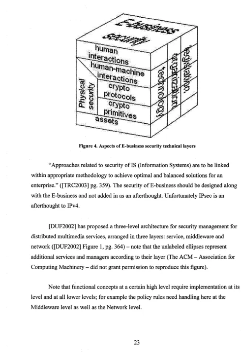
The “E-Business Security” figure used in section 2.3.1., “Other Management
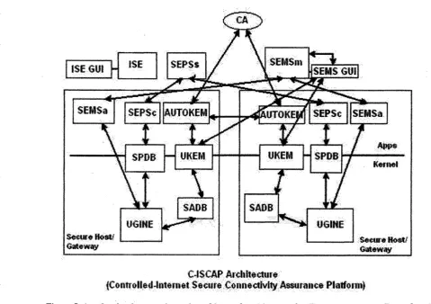
Proposals”, is redrawn from [TRC2003] with permission from Elsevier. The “C-ISCAP”
figure used in section 2.3.1. is reproduced (redrawn) with kind permission of Springer
Science and Business Media ([PAR2002], Figure 1, pg. 383, © Springer-Verlag Berlin
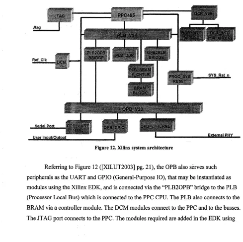
Heidelberg 2002). The figure illustrating the Xilinx system architecture in section 3.1.4.,
“Architecture Provided by Xilinx” ([XILUT2003] pg 21), was published by Xilinx in
order that it “may be used in any form that would benefit the professor and students,”
[XILTMAT]. The figures illustrating AES in section 3.1.1.1., “Overview o f AES”, are
TABLE OF CONTENTS
ABSTRACT... iii
DEDICATION ...iv
ACKNOWLEDGEMENTS...v
LIST OF TABLES... xiv
LIST OF FIGURES... xvi
LIST OF ABBREVIATIONS... xx
A B.l. Acronyms... xx
AB. 1.1. General...xx
A B .l.2. Technical...xx
AB.2. Abbreviations... xxiv
AB.2.1. General...xxiv
AB.2.2. Technical...xxv
Chapter...1
I. INTRODUCTION... 1
1.1. Motivation... 1
1.2. Overview of IPsec... 2
1.2.1. Key Exchange... 4
1.2.1.1 .Main M ode...4
1.2.1.2.Aggressive M ode... 4
1.2.1.3.Quick Mode... 5
1.2.1.4.Key Exchange - Conclusions...5
1.2.2. Security Policy Database and SM IB... .l5 1.2.3. Security Associations...6
1.2.4. Services...7
1.2.4.1 .Authentication Header Protocol... 7
1.2.4.2.Encapsulating Security Payload Protocol...7
1.2.4.3.Anti-Replay Service... 8
1.2.5. Modes of Operation...8
1.3. Previous W ork ...8
1.4. Problem Statement...9
1.7. Embedded Systems... 12
1.8. O bjectives... 13
1.9. Thesis Organization... 13
II. R EV IEW O F LITERA TU RE... 15
2.1. Introduction... 15
2.1.1. History of IPsec...15
2.1.2. Government Politics...16
2.1.3. The Standards Process - Outcome... 16
2.1.4. Applicability o f IPsec... 17
2.1.4.1 .Neighbour Discovery Protocol (NDP)... 17
2 .1.4.2.IP Mobility... 17
2.1.4.3.Network Management Protocols... 18
2.1.4.4.Streaming Multimedia... 18
2.2. Operational Aspects o f IPsec...18
2.2.1. Key Exchange...18
2.3. Management and Architecture... 22
2.3.1. Other Management Proposals... 22
2.3.2. The Erfani Patent... 26
2.4. Implementations o f IPsec...28
2.4.1. Software Implementations...28
2.4.2. Hardware Implementations... 29
2.4.2.1.FPGA Implementations...29
2.4.2.2.FPGA Implementations of Primitives...30
2.4.2.2.1.AE S ...30
2.4.2.2.2.Hashe s ...31
2.4.2.3.ASIC (Application-Specific Integrated Circuit) Implementations... 31
2.4.2.4.ASIC Implementations o f Primitives...32
2.4.3. Conclusion of the “Implementations” Section i... 32
2.5. An IPsec Application... 33
2.6. High-Level Synthesis for Hardware Implementations...33
2.7. Random Number Generators... 34
III. DESIGN AND M ETH O D O LO G Y ...37
3.1. Design o f an FPGA AES Hardware Accelerator... 37
3.1.1. Introduction... 37
3.1.1.1 .Overview o f A E S... 37
3.1.1.1.2.Substitute (“Sub”) Bytes... 40
3.1.1.1.3.Shift Rows... 40
3.1.1.1.4.Mix Columns...41
3.1.2. Technology... 42
3.1.2.1.Specific Virtex-4 FX12 FPGA Features... 43
3.1.2.2.ML403 Board Features...44
3.1.3. Selection o f the Base Design... 44
3.1.3.1.Some Aspects of the Usselmann Design... 45
3.1.4. Architecture Provided by X ilinx...45
3.1.5. VHDL in Xilinx... 48
3.1.6. Working with the Xilinx T ools...51
3.1.6.1 .Simulation Test Methodology... 53
3.1.6.2.Software Loading, Running and Debugging... 53
3.1.7. AES Design Done in this W ork...54
3.1.7.1.Core Design and other Modifications...54
3.1.7.2.Additional AES Implementation Features... 61
. 3.1.7.2.1. Autoload... 61
3.1.7.2.2.Key Expand Readout, Storage and Readback.61 3.1.7.2.3.Cipher-Block Chaining (CBC) M ode... 63
3.1.7.2.4.Timing Diagnostic Output for Test... 64
3.1.7.2.5.A “Stepper” Version of the Decryptor... 65
3.1.8. Test and Demonstration Software... 66
3.1.8.1 .CLI and Simpler Programs...66
3.1.8.2.The AES Demonstration GUI, “AESfile” ... 69
3.1.8.2.1.The ML403 Board C ode... 69
3.1.8.2.2.The PC Demonstration GUI, “AESfile” ... 70
3.2. Design of a Combination LFSR-CASR Pseudo-Random Number Generator... 72
3.2.1. Selection of the Base Design...72
3.2.2. Description of the Tkacik-Villar LFSR-CASR PRNG ...72
3.2.3. Test Methodology and Use in this Work... 73
3.3. Design of an IPsec Implementation, “IPsecImp”, Using the Five-Layer Security Framework... 74
3.3.1. C vs. C++ for Embedded Systems... 74
3.3.2. Top-Level Design of a Peer...74
3.3.3. SMIB (Security Management Information Data Base)...80
3.3.3.1 .The Policy Layer... 80
3.3.6. Board-GUI Reliable Data Transfer...83
3.3.7. The Services Layer... 86
3.3.7.1.The ESP Service...87
3.3.7.2.The AH Service...89
3.3.8. The Mechanisms Layer... 90
3.3.8.1. The Encryption Mechanism...90
3.3.8.1. The HMAC Mechanism...92
3.3.9. The Primitives Layer...92
3.3.9.1.The Hash Prim itive... 92
3.3.9.2.The Encryption Primitive... 93
3.3.9.3.The RNG Primitive... 95
3.3.10. Versions...96
3.4. Design of a Test and Demonstration GUI, “IPsecGUI” ... 98
3.4.1. Test Methodology... 106
3.5. Design o f a CLI Version, “IPsecLoop,” to Facilitate Testing 108 3.5.1. Test Methodology... 109
IV. ANALYSIS OF RESULTS...112
4.1. The AES Accelerator... 112
4.1.1. Simulation Results... 112
4.1.2. FPGA Usage...113
4.1.3. AES Performance Results... 114
4.1.3.1.AES Core Performance using Small Software Test Programs...114
4.1.3.2.AES Performance with the “AESfile” G U I...117
4.2. The LFSR-CASR PR N G ...118
4.3. Performance Results from “IPsecImp”, “IPsecGUI” and “IPsecLoop” ... 121
4.3.1. Demo, of Processing the Largest Possible Packet 121 4.3.2. Demo, of Correct AES Encryption in “IPsecGUI” 123 4.3.3. “IPsecLoop” Results... 125
4.3.3.1 .Version 4, with “IPsecLoop” and “IPsecGUI” Comparison... 12*6 4.3.3.2.Version 6 Compared to Ver. 4 ... 128
4.3.3.3.Version 7 Compared to Ver. 6 and 4 ...130
4.3.3.4.Version 8 Compared to Ver. 7 ... 134
V. CONCLUSIONS AND RECOMMENDATIONS...141
5.1. The AES Implementation... 141
5.2. The LFSR-CASR PRNG Implementation... 143
5.3. The IPsec Implementation... 143
5.4. Recommendations for Future Work...146
5.4.1. The AES Implementation... 146
5.4.2. The LFSR-CASR PRNG Implementation... 147
5.4.3. The IPsec Implementation... l47 APPENDICES ...151
A. Pseudo-Code... 151
A.I. IPsecIm p... 151
A.1.1. The SMIB...151
A. 1.1.1 .The Overview and Top Two L ayers... 151
A. 1.1.2.The Policies... 151
A.1.1.3.The Lower Three Layers (within the Overview) ..152
A. 1.2. The SADB... 153
A .I.3. Top-Level Loop... 153
A. 1.4. Packet Processing, or OSI Layers... 154
A. 1.4.1.IP Layer...154
A. 1.4.2.IPsec Layer... 154
A. 1.4.3 .Link Layer... 155
A. 1.5. Reliable Data Transfer...155
A. 1.5.1 .Send Algorithm... 155
A. 1.5.2.Receive Algorithm ...156
A. 1.6. The AH Service... 156
A. 1.7. The ESP Service... 157
A. 1.8. The HMAC Mechanism...157
A. 1.9. The Encryption Mechanism... 158
A.1.10.L4 (Mechanism) SPI Tracking Storage... 159
A. 1.11.The Hash Primitive... 159
A .I.12.The RNG Prim itive...159
A. 1.12.1.Get or Set the State...159
A.1.12.2.Resetthe State (to all “ l ”s ) ...159
A .I.12.3.Seed the RNG...160
A. 1.12.4.Generate a Random Number...160
A .I.13.The AES-128 Primitive...160
A. 1.13.2.IV Load to the Core... 160
A.1.13.3.The Encrypt or Decrypt Function... 161
A.2. IPsecLoop... 161
A.2.1. Top-Level Loop... 161
A.2.2. Packet Processing, or OSI Layers...162
A.2.2. l.IP Layer... 162
A.2.2.1.IPsec Layer... 162
A.3. IPsecGUI... 162
A.3.1. Packet processing test setup... 162
A.3.2. Packet processing timer processing...163
B. Experimental D ata ...164
B. 1. Simulation Results... 164
B.1.1. Encryption...164
B. 1.1.1.Encryption-w ith All Intermediate Step Results.. 164
B.1.1.2. Autoload... 1& B.1.1.3.Cipher-Block Chaining M ode...170
B.1.2. Decryption...171
B.2. Tabulated Data from “IPsecLoop” Oscilloscope Testing 172 B.2.1. Version 4, with “IPsecLoop” and “IPsecGUI” Comparison... 172
B.2.1.1.AH Transport...172
B.2.1.2.AH Tunnel... 173
B.2.1.3.ESP Transport... 173
B.2.1.4.ESP Tunnel... 174
B.2.2. Version 6 Compared to Ver. 4... 175
B.2.2.1.ESP Transport...175
B.2.2.2.ESP Tunnel... 176
B.2.3. Version 7 Compared to Ver. 6 and 4 ... 177
B.2.3.1.AH Transport... 177
B.2.3.2.AH Tunnel... 178
B.2.3.3.ESP Transport...179
B.2.3.4.ESP Tunnel... 180
B.2.4. Version 8 Compared to Ver. 7... 180
B.2.4.1.AH Transport... 180
B.2.4.2.AH Tunnel... 181
B.2.4.3.ESP Transport... 182
B.2.4.4.ESP Tunnel... 183
R. 1. Journal and Conference Papers...185
R.2. Books, General Papers and other Resources...190
R.3. R F C s ... 194
R.4. Websites...195
L IS T O F T A B L E S
Ta b l e 1. Ke y e l e m e n t so fa Se c u r i t y Po l ic y Da t a b a s e ( S P D ) ... 6
Ta b l e 2 . Ke ye l e m e n t s o fa Se c u r i t y As s o c i a t i o n Da t a b a s e...6
Ta b l e 3 . Th e A E S r o u n dc o n s t a n t (h e x) ... 3 9
Ta b l e 4 . IE E E V H D L s t d_l o g icv a l u e s... 4 9
Ta b l e 5 . X C 4 Y F X 1 2 d e v i c eu t i l i z a t i o n s u m m a r y (m o s tr e c e n tb u i l d - Ma r. 1 2 ,
2 0 0 7 ) ... 113
Ta b l e 6 . Ob s e r v e d A E S p e r f o r m a n c ei n-c o r ea n da s u s e db y s o f t w a r e 1 1 5
Ta b l e 7 . A E S c o r er a t e sa c h i e v e d i nt h isw o r ka n d i nt h el i t e r a t u r e... 1 1 7
Ta b l e 8. Pa c k e tp r o c e s s i n g t im e sc o m p a r e d t o ar e s u l tf r o m t h e l i t e r a t u r e
[ K E R 1 9 9 7 ] ... 1 3 8
Ta b l e 9 . (g r o u p): Pa c k e tp r o c e s s i n g r a t e s a n d c o m p a r i s o nw it h t h el i t e r a t u r e
...1 3 9
Ta b l e 10. A H Tr a n s p o r tt a b u l a t e d d a t a - v e r. 4 , w it h “IPs e cLo o p” a n d
‘T Ps e cG U I ” c o m p a r i s o n... 1 7 2
Ta b l e 11. A H Tu n n e lt a b u l a t e d d a t a - v e r. 4 , w it h “IPs e cLo o p” a n d “IPs e cG U I ”
c o m p a r i s o n... 173
Ta b l e 1 2 . E S P Tr a n s p o r tt a b u l a t e d d a t a- v e r. 4 , w it h “IPs e cLo o p” a n d
“IPs e cG U I ” c o m p a r i s o n... 1 7 4
Ta b l e 13. E S P Tu n n e l t a b u l a t e d d a t a - v e r. 4 , w it h “IPs e cLo o p” a n d “IPs e cG U I ”
c o m p a r i s o n... 1 7 5
Ta b l e 14. E S P Tr a n s p o r tt a b u l a t e d d a t a - v e r. 6 c o m p a r e dt ov e r. 4 ... 1 7 6
Ta b l e 1 5 . E S P Tu n n e l t a b u l a t e d d a t a - v e r. 6 c o m p a r e dt ov e r. 4 ... 1 7 7
Ta b l e 17. AH Tu n n e l t a b u l a t e d d a t a - v e r. 7 c o m p a r e d t ov e r. 4 ... 179
Ta b l e 18. ESP Tr a n s p o r tt a b u l a t e d d a t a - v e r. 7 c o m p a r e dt o v e r. 6 a n d 4 ....179
Ta b l e 19. ESP Tu n n e l t a b u l a t e d d a t a - v e r. 7 c o m p a r e dt o v e r. 6 a n d 4 ... 180
Ta b l e20. AH Tr a n s p o r tt a b u l a t e d d a t a - v e r. 8 c o m p a r e d t ov e r. 7 ...181
Ta b l e 21. AH Tu n n e l t a b u l a t e d d a t a - v e r. 8 c o m p a r e d t ov e r. 7 ... 182
Ta b l e 22. ESP Tr a n s p o r t t a b u l a t e d d a t a - v e r. 8 c o m p a r e dt o v e r. 7 ...183
LIST OF FIGURES
Fi g u r e 1. Th e O S I m o d e la d a p t e d t o f iv el a y e r s f o rt h e In t e r n e t - a l s o s h o w i n g
IPs e c... 3
Fig u r e 2 . Qu i c k m o d e... 5
Fig u r e 3 . Fu n c t i o n a lv s. t e c h n i c a ll a y e r s... 10
Fi g u r e 4 . As p e c t s o f E -b u s i n e s s s e c u r i t yt e c h n i c a ll a y e r s... 2 3
Fig u r e 5. An o t h e rim p l e m e n t a t i o n-o r i e n t e d l a y e r e da r c h i t e c t u r e f o r IPs e c
m a n a g e m e n t. Re p r o d u c e d w it hk i n d p e r m i s s i o n o f Sp r i n g e r Sc i e n c e a n d
Bu s i n e s s Me d i a...2 4
Fig u r e 6 . Th ef i v e-l a y e r s e c u r i t yf r a m e w o r k, a p p l i e dt o IPs e c...2 7
Fig u r e 7 . A E S a d d r o u n d k e y...3 9
Fig u r e 8 . A E S "s u b"-b y t e s... 4 0
Fig u r e 9 . A E S s h if tr o w s... 41
Fig u r e 1 0 . A E S m i xc o l u m n sa p p l i c a t i o n... 4 2
Fig u r e 11. A p h o t o g r a p h o ft h e Xil i n x M L 4 0 3 b o a r d... 4 3
Fig u r e 12. Xi l i n x s y s t e m a r c h i t e c t u r e... 4 6
Fig u r e 1 3 . A E S e n c r y p t o r a n d d e c r y p t o rm o d u l e s a n d h i e r a r c h y... 5 4
Fig u r e 1 4 . Big-e n d i a n d a t a o r i e n t a t i o na n d c o r e 1 0 r e g is t e ru s a g e... 5 5
Fig u r e 15. A E S e n c r y p t o r t im in gp l a n... ..5 8
Fig u r e 16. A E S d e c r y p t o r t im in gp l a n ...5 9
Fig u r e 17. Co n t r o l b i tl o c a t i o n s i n s l v_r e gO f o r b o t h A E S u s e rp e r i p h e r a l s....6 5
Fig u r e 18. A "s c r e e n s h o t" o ft h e “A E Sf il e” d e m o n s t r a t i o n...71
F i g u r e 19. T h e P o l i c y l a y e r a n d u p p e r p o r t i o n o f t h e M a n a g e m e n t l a y e r - a n
Fig u r e 2 0 . Th e l o w e rp o r t i o n o f t h e Ma n a g e m e n tl a y e r - a n a m b i t i o u sd e s i g n.7 5
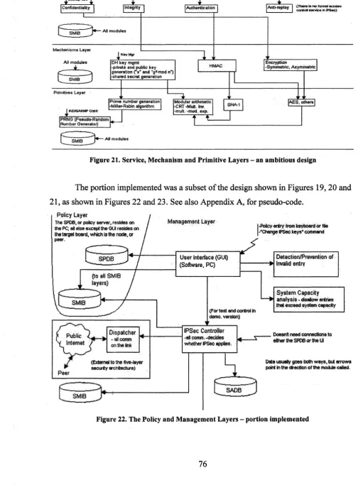
Fig u r e 2 1 . Se r v i c e, Me c h a n i s m a n d Pr im it iv e La y e r s - a n a m b i t i o u sd e s i g n...7 6
Fig u r e 2 2 . Th e Po l ic ya n d Ma n a g e m e n t La y e r s - p o r t io ni m p l e m e n t e d... 7 6
Fig u r e 2 3 . Th e Se r v i c e, Me c h a n i s ma n d Pr im it iv e l a y e r s - p o r t i o n i m p l e m e n t e d
... 7 7
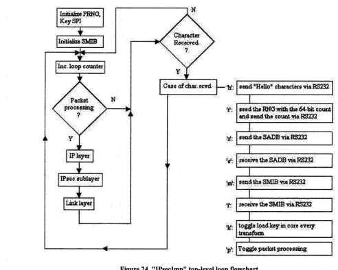
Fig u r e 2 4 . "IPs e cIm p" t o p-l e v e ll o o pf l o w c h a r t...7 8
Fig u r e 2 5 . Th e IPs e c l a y e rf l o w c h a r t...83
Fig u r e 2 6 . Th er e l i a b l e d a t a t r a n s f e r "s e n d" f l o w c h a r t... 8 5
Fig u r e 2 7 . Th er e l i a b l e d a t a t r a n s f e r "r e c e i v e" f l o w c h a r t...8 6
Fig u r e 2 8 . Th e E S P s e r v i c e f l o w c h a r t...8 8
Fig u r e 2 9 . Th e A H s e r v i c e f l o w c h a r t...9 0
Fig u r e 3 0 . Th ee n c r y p t i o n m e c h a n i s m f l o w c h a r t... 91
Fig u r e 3 1 . Th e H M A C m e c h a n i s m f l o w c h a r t... 9 2
Fig u r e 3 2 . En c r y p t i o n p r im it iv e I V a n d k e y l o a d f l o w c h a r t s... 9 4
Fig u r e 3 3 . Th e e n c r y p t i o n p r im it iv ef l o w c h a r t... 9 5
Fig u r e 3 4 . Th e h a s h a n d p s e u d o-r a n d o m n u m b e rg e n e r a t o r f l o w c h a r t s... 9 6
Fig u r e 3 5 . Op e r a t i o no f "Ke yIsAl w a y sTr e a t e dAsNe w" a n d t h e s e e d i n go ft h e
R N G in “IPs e cG U I ” ... 9 9
Fig u r e 3 6 . Th e “IPs e cG U I ” h e l pw i n d o w... 1 0 0
Fig u r e 3 7 . Th e “IPs e cG U I ” S M IB d i a l o g... 101
Fig u r e 3 8 . Th e “IPs e cG U I ” S A D B d i a l o g...1 0 2
Fig u r e 3 9 . "IPs e cG U I" p a c k e tp r o c e s s i n g s e t u pf l o w c h a r t... 1 0 4
Fig u r e 4 1 . A "s c r e e n s h o t" o ft h eo p e r a t i o no f "IPs e cG U I " ...1 0 6
Fig u r e 4 2 . Os c i l l o s c o p em e a s u r e m e n t o f A H Tr a n s p o r to u t g o i n gp r o c e s s i n g
TIME WITH A 40-BYTE PACKET... !...I l l
Fig u r e 4 3 . Di s t r i b u t i o n o ft e n t h o u. 3 2 -b i tn u m b e r sf r o m t h e L F S R - C A S R P R N G
i n 2 5 6 r a n g e s... 1 1 9
Fig u r e 4 4 . Di s t r i b u t i o n o fa h u n. t h o u. 3 2 -b i tn u m b e r s f r o m t h e L F S R - C A S R
P R N G IN 4 0 9 6 RANGES... 1 1 9
Fig u r e 4 5 . Di s t r i b u t i o n o ft e n t h o u. 1 2 8 -b i tn u m b e r s f r o m t h e L F S R - C A S R P R N G
i n 2 5 6 r a n g e s... 1 2 0
Fig u r e 4 6 . Di s t r i b u t i o n o fa h u n. t h o u. 1 2 8 -b i tn u m b e r sf r o m t h e L F S R - C A S R
P R N G i n 4 0 9 6 r a n g e s...121
Fig u r e 4 7 . Pa c k e tp r o c e s s i n g u s i n g t h el a r g e s t IPs e cp a c k e tp o s s i b l e in E S P ,
Tu n n e lm o d e... 123
Fig u r e 4 8 . "IPs e cG U I" "s c r e e n s h o t" s h o w i n g c o r r e c te n c r y p t i o n... 1 2 4
Fig u r e 4 9 . S A D B s e t t i n g su s e d i nt h ep r e v i o u s f i g u r e... 125
Fig u r e 5 0 . A H Tr a n s p o r tp a c k e tp r o c e s s i n g t im e s (v e r 4 ) , c o m p a r i n g
MEASUREMENTS MADE USING “IPSECLOOP” TO THOSE MADE USING “IPSE C G U I” . . . 1 2 7
Fig u r e 5 1 . E S P Tr a n s p o r tp a c k e tp r o c e s s i n g t im e s - v e r. 6 v s . v e r. 4 ...1 2 8
Fig u r e 5 2 . E S P Tu n n e l p a c k e tp r o c e s s i n gt im e s - v e r. 6 v s . v e r. 4 ... 1 2 9
Fig u r e 5 3 . A H Tr a n s p o r tp a c k e tp r o c e s s i n g t im e s - v e r. 7 v s . v e r. 4 ...1 3 0
Fig u r e 5 4 . A H Tu n n e l p a c k e tp r o c e s s i n g t im e s - v e r. 7 v s . v e r. 4 ... 131
Fig u r e 5 5 . E S P Tr a n s p o r tp a c k e tp r o c e s s i n g t im e s - v e r. 7 v s . v e r. 6 a n d 4 ...1 3 2
Fig u r e 57. AH Tr a n s p o r t p a c k e tp r o c e s s i n g t im e s - v e r. 8 vs. v e r. 7 ...134
Fig u r e 58. AH Tu n n e l p a c k e tp r o c e s s i n g t im e s - v e r. 8 vs. v e r. 7 ... 135
Fig u r e 59. ESP Tr a n s p o r tp a c k e tp r o c e s s i n g t im e s - v e r. 8 vs. v e r. 7 ...136
Fig u r e 60. ESP Tu n n e l p a c k e tp r o c e s s i n g t im e s - v e r. 8 vs. v e r. 7... 137
Fig u r e 61. En c r y p t i o n s i m u l a t i o n "s c r e e n s h o t" - u p p e r l e f tq u a d r a n t o fv i e w ...165
Fig u r e 62. En c r y p t i o n s i m u l a t i o n "s c r e e n s h o t" - l o w e rl e f t q u a d r a n to f v i e w 166 Fig u r e 63. En c r y p t i o n s i m u l a t i o n "s c r e e n s h o t" - u p p e r r ig h tq u a d r a n t o fv i e w ... 167
Fig u r e 64. En c r y p t i o n s i m u l a t i o n "s c r e e n s h o t" - l o w e rr ig h t q u a d r a n to fv i e w 168 Fig u r e 65. En c r y p t i o n s i m u l a t i o n “s c r e e n s h o t,” s h o w i n g a u t o l o a d...169
Fig u r e 66. En c r y p t i o n s i m u l a t i o n “s c r e e n s h o t,” s h o w i n gCBC m o d e...170
LIST OF ABBREVIATIONS
AB. 1. Acronyms
AB.1.1. General
AKA - Also Known As
BC - British Columbia - the Western-most Canadian province. DST - Daylight Saving Time
DUANWKWYM - Don’t Use Acronyms; Nobody Will Know What You Mean! IBM - International Business Machines: a very large and famous company ID - Identity
NA - Not Applicable PC - Personal Computer S W -S o ftw are
US - United States
USA - United States o f America
A B .l.2. Technical
3DES - Triple-DES - see DES
ACK - Acknowledgement: a non-printing ASCII control character ACM - Association for Computing Machinery
AES - Advanced Encryption Standard - Rijndael, as of Fall 2000.
AH - Authentication Header - authenticating the packet contents in IPsec ANSI: American National Standards Institute
ASCII - ANSI Standard Code for Information Interchange ASIC - Application-Specific Integrated Circuit
b - bit(s) - single binary digit(s)
B - Byte(s) - fundamentally defined as a group o f eight bits, i.e., an “octet” of bits. Also, the “B” programming language, which stands for Bell labs, where it was invented. BDM - Background Debug Mode - see PCIV
BE - Big-Endian (see LE)
BIOS - Basic Input-Output System
BITS - Bump-In-The-Stack - the addition of processing by insertion and integration into existing layered protocols. Compare BITW.
BITW - Bump-In-The-Wire - the addition of processing devices placed downstream in the dataflow from the originator. Compare BITS.
BRAM - Block RAM
bps - bits per second. Compare Bps. Usually about ten times the latter due to parity and other bits included with every byte.
Bps - Bytes per second. Compare bps.
BSB - Base System Builder - a “wizard” in Xilinx EDK
C++ - an object-oriented programming language; successor to C CA - Certificate Authority
CASR - Cellular Automata Shift Register - see LFSR
CBC - Cipher-Block Chaining - a cipher feedback mode in which the output o f the previous encrypted block is XORed with the next block of plaintext before that is encrypted. See ECB.
C-ISCAP - Controlled Internet Secure Connectivity Assurance Platform - author- specific; see [PAR2002].
CLI - Command-Line Interface - compare GUI CMOS - Complementary Metal-Oxide Semiconductor
COPS-PR - Common Object Policy Service for PRovisioning - RFC 3084 CPLD - Complex Programmable Logic Device
CPU - Central Processing Unit
CSPRNG - Cryptographically-Secure PRNG DCM - Digital Clock Manager
DH - Diffie-Hellman dDoS - Distributed DoS
DES - Pronounced “Dez” (short “e”) - (The) Data Encryption Standard, US National Bureau of Standards, FIPS Publication 46, January 1977
DMA - Direct Memory Access
DNS - Domain Name Service - the protocol used on the Internet, for the WWW, for translation between IP addresses and website names.
DOI - Domain O f Interpretation DoS - Denial of Service
DOS - Disk Operating System (owned and developed by Microsoft, Inc.) DSP - Digital Signal Processing
E - Electronic, as in “E-business,” “email,” etc.
ECB - Electronic Code Book - a block cipher mode that uses no feedback. Each block is encrypted independently of the others. Pipelining or parallel encryption is possible, but is cryptographically, weaker, since identical blocks o f plaintext will result in identical blocks of ciphertext. See CBC.
ECC - Elliptic Curve Cryptography
ECE - Electrical and Computer Engineering - still a fairly new amalgamation as of the 2000s
EDK - Embedded Development Kit - Xilinx software - see ISE
EEPROM - Electrically-Erasable PROM - often pronounced “E-squared PROM” ESP - Encapsulating Security Protocol - encrypting the packet contents in IPsec ETX - End-of-Text: a non-printing ASCII control character
FAE -Field Applications Engineer
FIPS - Federal Information Processing Standard - a US (United States) establishment FPGA - Field-Programmable Gate Array
FSL - Fast Simplex Link FTP - File Transfer Protocol GF - Galois Field
GDB - GNU DeBug - an open-source debugger for embedded systems
GPIO - General Purpose - or Parallel - 1 0 GPL -GNU Public License
GUI - Graphical User Interface - compare CLI
HAS-160 - a cryptographic hash function designed for use with the Korean KCDSA digital signature algorithm [WIKIP].
HDL - Hardware Design Language, such as VHDL or Verilog HLS - High-Level Synthesis
HMAC - Hashed Message Authentication Code HO - High-Order - see LO
HOB - High-Order Byte
HTTP -HyperText Transfer Protocol IC - Integrated Circuit
IDE - Integrated Development Environment
IEEE - Institute of Electrical and Electronics Engineers
IETF - Internet Engineering Task Force - see References - Websites. IIC - Inter-IC bus
IKE - Internet Key Exchange 10 - Input-Output
IP - Internet Protocol; also Intellectual Property (used to refer to HDL implementations) IPIC - IP Interconnect, Xilinx - IP: Intellectual Property
IPIF - IP InterFace, Xilinx - IP: Intellectual Property IPsec, IPSec - IP Security
IPSP - Internet Protocol Security Policy
IPSPE - unknown: see IPSP, and [KEN1994]; possibly IPSP Extended. IPv4 - IP version 4 - see IP
IS - Information Systems
ISAKMP - Internet Security Association and Key Management Protocol [STA2003], pg.
202
ISE - Integrated Software Environment (Xilinx software - see EDK); also Internet Security Evaluation system [PAR2002].
IV - Initial (or Initialization) Vector
JTAG - Joint Test Action Group, IEEE standard 1149.1 L - Layer, Laptop
LAN - Local Area Network LCD - Liquid Crystal Display LE - Little-Endian (see BE) LED - Light-Emitting Diode
LFSR - Linear Feedback Shift Register - see CASR LGPL - Lesser GNU Public License
LO - Low-Order - see HO
LSI - Low Scale Integration (or Large Scale Integration) - see MSI and VLSI LU T -L ook-U p Table
MAC - Message Authentication Code - see HMAC
MD5 - Message Digest algorithm 5 - one of a series of message digest algorithms designed by Professor Ronald Rivest of MIT.
MITM - Man In The Middle, or Monkey (saboteur) In The Middle MS - Microsoft (company) - see MSVC++V6
MSI - Medium Scale Integration - see LSI and VLSI MSVC++V6 - MS Visual C++ Version 6.0
NAK - Negative Acknowledgement: a non-printing ASCII control character NDP - Neighbour Discovery Protocol
NGM - New Group Mode, an IPsec key exchange utility mode. NRE - Non-Recurring Engineering (costs)
OP - OutPut
OPB - On-Chip Peripheral Bus, Xilinx OS - Operating System
OSI - Open Systems Interconnection
P - PC: Personal Computer, often intended to mean an “IBM” (now generic) PC. PAR - Place And Route
PCB - Printed-Circuit Board
PCIV - the Xilinx “Parallel Cable IV” (pronounced “PC-four”) cable. (Used for BDM) PDA - Personal Digital Assistant
PGP - Pretty Good Privacy, a software package that provides confidentiality and authentication at the application layer [PGPI].
PIB - Policy Information Base - RFC 3159. PLB - Processor Local Bus, Xilinx
PPC - Power PC, i.e., “Power Personal Computer”, a microprocessor that can perform as Intel x86 as well as Motorola 68x CPUs.
PRNG - Pseudo-RNG - see CSPRNG
PROM - Programmable ROM - see EEPROM PSTN - Public Switched Telephone Network
PU - frequency of occurrence Per Unit (per each one), as “percent” is per each hundred. QoS - Quality of Service. Types of: “Hard”: specific numerical guarantees are made and
kept. “Soft”: higher-priority data flows are given higher-priority access to the system. RACE - Research and development in Advanced Communications technologies in
Europe. Used in RIPEMD-160 (qv). RADAR - RAdio Detection And Ranging
RAM - Random-Access Memory - see ROM, BRAM, SRAM RC - ReConfigurable (hardware) such as FPGAs and CPLDs.
RFC - Request For Comment: an IETF document that can be informational, a proposed standard, or an IETF standard.
RIPEMD-160 - RACE (qv) Integrity Primitives Evaluation Message Digest - a 160-bit message digest algorithm (and cryptographic hash function) developed in Europe.
[WIKIP]
RNG - Random-Number Generator - see PRNG, CSPRNG ROM - Read-Only Memory - see PROM, EEPROM, RAM
RTP - Real-time Transport Protocol: i.e., a Transport Protocol designed for real-time communications such as streaming multimedia, or possibly telepresence.
S - Substitution, as in S-Box SA - Security Association
SHA-1 - Secure Hash Algorithm 1 - successor to MD5. SLA - Service Level Agreement
SMIB - Security Management Information Database SPI - Security Policy Index - uniquely identifies an S A SPD or SPDB - Security Policy Database
SRAM - Static RAM
STX - Start-of-Text: a non-printing ASCII control character SWAN - Secure WAN - see WAN
TCP - Transmission Control Protocol - the main Transport-level protocol used on the Internet, providing a guarantee of reliable delivery and correct packet ordering. TTL - Time To Live - field of an Internet Protocol (IP) datagram
UART - Universal Asynchronous Receiver-Transmitter - an integrated device that can perform such communication protocols as RS232
UDP - User Datagram Protocol - a simple Transport-level protocol used on the Internet UML - The Unified Modeling Language
VHDL - VHSIC HDL
VHSIC - Very High-Speed Integrated Circuit - see VHDL VLIW - Very Long Instruction Word
VLSI - Very Large Scale Integration (see MSI and LSI) VPN - Virtual Private Network
XMD - Xilinx Microprocessor Debug
XOR - Exclusive-OR - a common operation in cryptography, since it is its own inverse WAN - Wide-Area Network
WEP - a standard for protecting 802. IX communications, “Wired Equivalent Privacy” - so-called; it is not really very strong.
WWW - The World-Wide Web, AKA, in some circles, as “The World-Wide Wait”. XST - Xilinx Synthesis Tool
AB.2. Abbreviations
AB.2.1. General
approx. - approximately demo. - demonstration dept. - department
Fig. - Figure, i.e., illustration. hun. - hundred
inc. - incoming out. - outgoing
rev. - revision (often synonymous with “ver.”, but sometimes used to denote sub-version levels)
sub. - substitute, or substitution; “sub” is also a complete word or prefix meaning “below”, “under” or “smaller”,
thou. - thousand
AB.2.2. Technical
app. - application dec. - decryption enc. - encryption F lash -F lash EEPROM hex. - hexadecimal
Hz - Hertz - cycles, or any repetitive occurrence, per second. The repetitive occurrence is simply a dimensionless count, so this unit has a dimension only o f inverse time. Rcon - Round constant
Chapter I
INTRODUCTION
1.1. Motivation
To begin with the virtually self-evident, companies need communications. In any
economy beyond that o f the 1700s (in the USA), electronic communications are needed.
Indeed, these are valuable to individuals for personal use, as well. Telegraph, telephone,
telex and facsimile systems performed all the services of electronic communication
systems in their day, for decades, since the 1800s, and it was not until the 1990s that the
Internet began to rise to predominance, replacing and supplementing those systems with
the mass ability to transmit documents. The facsimile machine has been largely rendered
redundant by email and the WWW (World Wide Web), and telephony is in the process o f
becoming an Internet application at the time of this writing, although it is not now
known, of course, if the entire legacy PSTN (Public Switched Telephone Network) will
be replaced by the Internet and if so, how long that will require.
Partly due to its public nature, and partly due to economies of scale, the Internet is
extremely economical to use, which gives a reason for companies and individuals to
make great use of it. However, since it is public, it is necessary to secure its use for
general privacy purposes. Today, generally only companies have the resources to perform
mass securing of Internet services, although personal software packages such as PGP
(Pretty Good Privacy) are available for individual use - PGP performs security services
at the user, or application layer [PGPI]. For mass use, companies use encryption to
implement VPNs (Virtual Private Networks), using the Internet as their own private
communication network. VPNs are technically available to individuals, since Microsoft
Windows XP, for one, is equipped to perform IPsec (Internet Protocol security), but its
setup still requires technical expertise and cooperation that are mostly beyond the abilities
o f unorganized individuals. Notably, the “Free S/WAN” movement and software package
Use of a public network gives some of the strongest possible reasons to adopt
security measures against attacks that threaten, although managers of private networks
are well advised to adopt additional security measures beyond the physical. Some attacks
and their countermeasures are as follows:
• Masquerade, unauthorized access, repudiation: need an authentication/access control service
• Message modification, replay: need an integrity service
• Spying: need a confidentiality service
• Denial of service (DoS)/unauthorized access: need an availability/access control service
These imply the existence of five basic services: authentication, integrity,
confidentiality, access control and availability. Two others are anti-replay (a form of
integrity, given that the time a message is sent should be counted as part o f its makeup),
and non-repudiation (which consists of authentication plus audit logging or message
retention).
The combination of “IP” (Internet Protocol) and “Security” creates the
abbreviation “IPsec”. Although it was originally intended to secure all IP transactions, it
found its most natural application in VPNs [FER1999]. IPsec can be thought of as an
adaptation o f the general concept of VPNs to the Internet [PER2000].
1.2. Overview of IPsec
The idea of IPsec dates back to 1994, and the most important four RFCs
(Requests For Comment) were issued in 1998 [STA2003]. They are: RFC 2401,
“Security Architecture for the Internet Protocol”, RFC 2402, “IP Authentication Header”,
RFC 2406, “IP Encapsulating Security Payload (ESP)”, and RFC 2408, “Internet Security
Association and Key Management Protocol (ISAKMP)” - see the “RFCs” subsection in
the References section - a full list of IPsec RFCs is available [IPS2005].
A brief overview of IPsec is presented here. A comprehensive and detailed
belongs, in the ECE department at the University of Windsor, by a previous Master’s
candidate; please see [FAH2005].
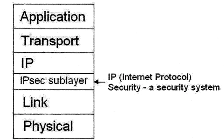
It is desirable to make the security system transparent to the user, for if the user
has to perform any operation to accomplish the security transform in addition to sending
the message, the additional burden will likely be refused, done carelessly, or, with the
best will in the world, absent-mindedly forgotten in the press of competing primary
duties. The IPsec layer or sublayer is located below the IP layer, just above the link layer
(see Figure 1 for the OSI model adapted to five layers for the Internet - OSI stands for
“Open Systems Interconnection”), and thus is transparent to the user, who generally deals
directly with only the Application layer.
(Internet Protocol)
Security - a security system
Figure 1. The OSI model adapted to five layers for the Internet - also showing IPsec
IPsec provides confidentiality, integrity, authentication, anti-replay services, and
can be used for non-repudiation and access control, although common implementations
of those two are typically weak (see the final paragraph in section 2.2.1. “Key
Exchange”). It does not provide a formal availability service, and suffers from weakness
in this area (see section 2.2.1., “Key Exchange”).
Application
Transport
I
p
IPsec sublayer
L .* •
ink
i p u f e i - »■ ' ;t
1.2.1. Key Exchange
There are three different modes of key exchange in IPsec: Main Mode, Aggressive
Mode, and Quick Mode. There are also some utility modes, such as NGM (New Group
Mode), used to negotiate a new group for Diffie-Hellman Key Exchange, carried out
under protection of IS AKMP (Internet Security Association and Key Management
Protocol) phase 1. Main Mode and Aggressive Mode are alternate modes that can be used
to establish the “Phase 1” SAs (Security Associations), whereas Quick Mode is an
exchange that uses the protection of the Phase 1 SAs to establish the Phase 2 SAs that are
the actual IPsec working SAs that protect the data packets ([ZH02000] pg. 1606).
1.2.1.1. Main Mode
The initiator sends a cookie and a proposed phase 1 SA. The responder replies
with a cookie and the accepted phase 1 SA. The initiator sends its Diffie-Hellman public
key and a nonce, and the responder replies with its Diffie-Hellman public key and nonce.
Both sides compute the Diffie-Hellman shared secret, or key. The initiator sends its
signed certificate to establish its identity and the responder replies with its signed
certificate ([AIE2002] Figure 3, pg. 55). Signing in this case means to encrypt a hash of
the message using the shared secret - in general, signing means encryption, using a
shared secret, or a private key in a public key cryptosystem, of the message itself or of a
hash of the message. A total of six messages are sent.
1.2.1.2. Aggressive Mode
In Aggressive Mode, only three messages are exchanged. The initiator cookie,
proposed Phase 1 S A, Diffie-Hellman public key and initiator ID (identity) are sent at
once, and the the responder replies with its own cookie, the accepted Phase 1 SA, its
Diffie-Hellman public k e y , its ID, as well as its signed certificate. The initiator then
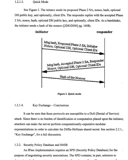
1.2.1.3. Quick Mode
See Figure 2. The initator sends its proposed Phase 2 SA, nonce, hash, optional
DH public key, and optionally, client IDs. The responder replies with the accepted Phase
2 S A, nonce, hash, optional DH public key, and optionally, client IDs. As a handshake,
the initiator sends a hash of the nonces ([ZH02000] pg. 1608).
It can be seen that these protocols are susceptible to a DoS (Denial o f Service)
attack. Since there is no burden of identification or computation placed upon the initiator,
attackers can make the server perform computationally-expensive modular
exponentiations in order to calculate the Diffie-Hellman shared secret. See section 2.2.1.,
“Key Exchange”, for a full discussion.
1.2.2. Security Policy Database and SMIB
An IPsec implementation requires an SPD (Security Policy Database) for the
purpose of negotiating security associations. The SPD contains, in part, selectors to
determine whether or not to process a packet, for a given policy of how to process the
in it ia t o r
responder
gash o f the
Figure 2. Quick mode
packet selected. The selectors can be set to “all”, as “wildcards”, and the sense o f the
selectors can be set as meaning either to select or not select the packets with the selected
characteristics. Using an SPI (Security Policy Index) to uniquely identify a Security
Association (SA), an SPD entry can refer to more than one SA, and a single SA can be
derived from more than one SPD entry, in which case more than one SPD entry would
have the same SPI - see Table 1 for an illustration.
From To Protocol Port Policy SPI(s)
1.1.1.1 2 2 2 .2 TCP 1000 ESP w. 3DES ! ’3
1.1.1.1 2 2 .2 2 * * ESP w.AES 2
Table 1. Key elements of a Security Policy Database (SPD)
In addition, it can be useful to define a Security Management Information
Database (SMIB), containing the SPD and other information useful to running a security
and communication system, such as the local address, clients served by the IPsec
operating entity, or node, the functional modules available to the system to do key
management and perform the other services noted before, and the parameters needed to
control them. See [KEN1994] for a list of ideas.
1.2.3. Security Associations
A security association (SA) defines the agreement under which two entities will
use IPsec to communicate, in a particular direction; i.e., two SAs are needed for
bidirectional communication. The S A contains, at a minimum, the addresses o f the
communicating entities, the protocol and mode to be used, the SPI, and the algorithms to
be used - see Table 2 for an illustration of a Security Association Database (SADB),
which contains the information specifying the node’s SAs.
From To Protocol Mode SPI Policy
2.2.2.2 1.1.1.1 ESP Tunnel 10 64-bit DES
1.1.1.1 2.2.22 ESP Transport 11 168-bit DES
1.2.4. Services
1.2.4.1. Authentication Header Protocol
The Authentication Header (AH) Protocol adds a header to IP packets, that
contains a signed hash of the message, to transform the packet into an IPsec packet. This
provides authentication and integrity services. The header also contains the SPI so that
the S A can be identified, a sequence number for anti-replay purposes, and some other
data, such as the type of header immediately following, and the “payload” length o f the
Authentication Header.
1.2.4.2. Encapsulating Security Payload Protocol
In the Encapsulating Security Payload (ESP) Protocol, each IP packet’s contents
are encrypted, providing confidentiality and encryption. The contents are first padded to
make them a natural number multiple of the encryption block size, and to provide space
for the padding length field itself, meaning that if the contents are already a multiple of
the block size, padding must still be added. A header is added that contains the SPI and
sequence number, and a variable-length authentication field is specified, following the
payload data. If an Initial Vector (IV) is included with the ciphertext, it is usually not
encrypted ([STA2003] pg. 183); in this work it was realized that if Cipher-Block
Chaining (CBC) were to be used, and the IV is first encrypted without chaining,
following which the IV is used, an attacker would be able to tell if the first block of data
happened to be all zeroes, because then the encrypted IV and the first encrypted block of
data would be identical (note that for the strongest possible security, security algorithms
are generally made thoroughly public in order to receive the most possible scrutiny). If
chaining were to be done from the encrypted IV, the encrypted IV would itself be the IV,
1.2.4.3. Anti-Replay Service
Each IPsec packet contains a 32-bit sequence number to prevent replay attacks. If
a packet with an identical sequence number is received, it is discarded. Also, if a packet
with a sequence number that is too old is received, it is discarded. O f course, if the packet
authentication fails, the packet is discarded. The foregoing are events that should be
logged for audit [STA2003]. A settable “window size” determines the lowest sequence
number that will be accepted, from the highest sequence number so far received. When
the sequence number overflows, the SA should be renegotiated, although whether that
will be done is generally also negotiated.
1.2.5. Modes o f Operation
Two modes of operation are defined for each of the AH and ESP protocol,
Transport Mode and Tunnel Mode. In Transport Mode, the IP packet’s header is modified
as needed for retransmission and the IPsec header is inserted following. Any transform,
such as ESP, is done only to the packet payload. In Tunnel Mode, a new IP header is
appended to the beginning of the IP packet, following which the IPsec header is added,
following which the entire IP packet is included, unchanged in AH protocol and
transformed only, in ESP. This allows the original IP packet to continue on unchanged
after its transmission as an IPsec packet, which is very useful when a gateway is
employed, and for VPNs.
1.3. Previous Work
As noted after, (see section 2.3.2., “The Erfani Patent”), in previous work in the
author’s group in the ECE department at the University of Windsor ([FAH2005] section
4.2, pp. 84-94, and Chapter V), a five-layer framework for the design o f a security system
was introduced. The five layers are: the Policy, Management, Services, Mechanisms and
Primitives layers (see section 2.3.2., after). These five layers were “fleshed out” into
modules and several operating scenarios were described. These are: an IPsec session
scenario, in which the security system is used to establish an S A and send a packet via
policies used for secure vs. very secure applications ([FAH2005] section 5.1.2, pg. 105),
and a description of a combination of SAs in which IPsec AH protocol packets are
tunnelled through an ESP SA between two routers ([FAH2005] section 5.1.3, pg. 106).
1.4. Problem Statement
Generally, the software approach to implementation is versatile, but resulting
implementations are relatively slow. Use o f “hardware”, or dedicated integrated circuits
(ICs) - or even LSI and MSI (Low Scale and Medium Scale Integration) ICs to perform
a task results in implementations that work much faster, but versatility suffers.
Cryptographic operations, such as encryption, decryption, hashing and random
number generation are generally extremely computationally intensive, making hardware
accelerators extremely desirable.
This leads to the question: How can the five-layer security architecture be used to
implement IPSec in hardware, given that the overhead of using cryptography mandates
hardware acceleration?
1.5. Motivation for General Layering
In implementation, breaking the task into implementation layers, from hardware,
to software drivers, middleware and user-interface layers is useful to make it manageable
and doable by a group of individuals or working groups, each o f which does his own
component. Modules can also be upgraded and replaced separately. Each layer uses the
services of the layer below (except for the lowest layer - in perhaps a system-limited
sense) to provide services to the layer above (except for the highest layer - again, in
perhaps a narrow sense). This was done in the seven-layer OSI model which specifies the
following layers, from top to bottom: Application, Presentation, Session, Transport,
Network, Link and Physical. The seven were reduced to five for the Internet: Application,
implemented via BITS (Bump-In-The-Stack), would fit at the bottom of the Network
(Packet), or IP layer, since IPsec is applied after packetization just before sending to the
Link layer - note that the diagrams in [FUM1998] (Figure 2, pg. 191), and in [HUN1998]
(Figure 11, pg. 1118), depicting IPsec between the IP and TCP (Transmission Control
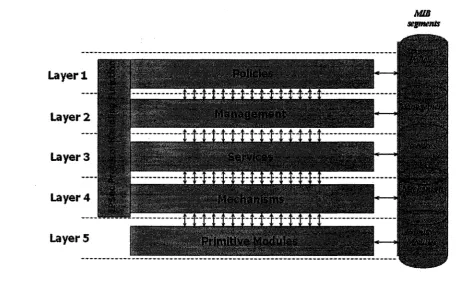
Protocol) layers, are not right.
It is also useful to break the task down into conceptual, functional, or managerial
levels, as in [ERF2003], which proposes five layers: Policy, Management, Services,
Mechanisms and Primitives (Figure 3).
Policies yanaaement Services f^sch&ftisms P iffn H m i User Interface;
Midcilwsre
(Sublayers)
Databases
Data control
Tasks -
H
Sub-tasks Math functions,
cryptography *1 /■' sVSfi?? y-*
'Drivers' . i f !>
M
Hardware
Figure 3. Functional vs. technical layers
As indicated in Figure 3, in a relation proposed in this work, a given functional
layer requires presence at its and all lower implementation layers; the lower
implementation levels have to contain “sub” functions to support the higher functionality.
Policies require entering from the user interface, presence in databases, and control of the
data. Management may require some entry from the user interface as well, but it at least
is specified by the data entered into the databases. Services and Mechanisms are tasks „
and subtasks, and primitives require the low-level math functions and cryptography.
Finally, in order for the electronic communications to proceed, the software must operate
the hardware via drivers.
It might theoretically be possible to be more efficient with an “ad hoc” unlayered
improvements or bug fixes would eventually become impossible, at some level of
complexity. Disadvantages of layering include the necessity of passing data down
through the multiple layers, which can slow down processing. Strict separation of layers
can prevent a successful system design if passing needed data is disallowed on the
grounds that it appears to “belong” only to one certain layer. A layer may duplicate
functionality present in another layer, perhaps due to insufficient communication and
planning between the respective working groups. An example of this latter inefficiency is
error checking and recovery, which is often done at the link layer as well as on “an end-
to-end basis” ([KUR2000], 3rd ed., pg. 47).
1.6. Motivation to use FPGAs
FPGAs (Field-Programmable Gate Arrays) contain thousands of blocks of
identical generic logic which can be configured via programming like a static RAM
(Random Access Memory) to operate in an extremely wide range of different behaviours.
They are cost-effective in production and testing since this can be done in-house with
affordable equipment, and devices are provided by manufacturers that make available
many resources (block RAM, clock dividers, etc.) in a structured way,
FPGAs offer some of the performance levels of hardware and also some o f the
versatility of software, since they can be reconfigured for different functionality, even
during runtime. Configuration files, or “bit files”, for programming the FPGA, can be
stored in memory, such as Flash EEPROM (Electrically-Erasable Programmable Read-
Only Memory), or “Flash”, and recalled at will. Stored configurations, such as encryption
schemes, can be compressed for storage [DAN2000]. Field upgrades for such things as
bug fixes and new standards are possible, even using pin-compatible devices [CHE2002].
FPGAs offer lower non-recurring engineering (NRE) costs compared to custom or
semi-custom ICs, such as ASICs (Application-Specific ICs), since they come ready
costs, such that if sales of more than 100,000 units occur, it would be more economical to
spend the NRE costs to produce an ASIC ([KHA2006] pg. 8, [OGA2004]).
Software running on a general-purpose processor can typically produce AES
(Advanced Encryption Standard - Rijndael is the name of the specific algorithm adopted)
throughputs of low tens o f Mbps (i.e., 30) [DAN2000], whereas FPGAs can achieve up to
176 Mbps implementing DES (the Data Encryption Standard) and up to Gbps rates
implementing AES; for example, speeds of 964 Mbps ([WOL2004] pp. 550, 554) and
1.197 Gbps [LUJ2005] have been reported (see section 2.4., “Implementations of IPsec,”
after). An ASIC processor achieved 2.29 Gbits/s of AES throughput in a 0.18pm CMOS
(Complementary Metal-Oxide Semiconductor) standard-cell technology in 2002
[SCH2002],
1.7. Embedded Systems
An embedded system is a computerized module or component containing built-in
software, usually on an IC chip, which is not changed in its normal course o f operation.
As part o f its computerization, it also contains a computer processor, but that is not a
defining characteristic, since non-embedded systems such as PCs (Personal Computers)
also contain processors. For example, in this work, the normal operation of the system
does not include loading and running the firmware, i.e., once the bit file, which contains
both the FPGA configuration (the “soft hardware”) and the (“firm”) software, has been
loaded to the board. Although this work involved loading the ML403 board on a regular
basis, every single time it was used, this can be seen as engineering development work,
not regular user operation, for which the bit file could be stored in the Flash EEPROM
(Electrically-Erasable Programmable Read-Only Memory) and automatically loaded at
bootup. The ML403 board can also be loaded by a user via a “flash card”, in which case
its status as an embedded system would be greatly mitigated. For another example, a PC
is not an embedded system, because the user operates it by loading programs to its RAM
IC chip or chips from its hard disk, such as by clicking with a “mouse”, in its normal
(the Basic Input-Output System), which historically could not be very easily changed by
the user at all (PCs first appeared in the early 1980s, and somewhat earlier, too, in a
general sense, before the IBM PC appeared on the market). Today, the BIOS chip can be
a Flash EEPROM, which can be changed by the user via a special procedure, not in its
normal course of operation. Another example of an embedded system might be a PDA
(Personal Digital Assistant), able to perform many applications. Another might be the
anti-lock braking module in a car. Yet another might be a coffee maker, in which the
software would most likely be present in a PROM, soldered directly to the PCB (Printed-
Circuit Board), to keep manufacturing costs low. Another might be a washing machine,
in which the PROM might conceivably be placed in a socket, for possible warranty
repairs. Another might be a “set-top box”, capable of having its software in its Flash
EEPROM updated “over the air” by the service provider. Clearly, the more easily the
software can be changed, and the more frequently it actually is, the less “embedded” the
system is.
1.8. Objectives
This work has the following objectives: (1) to produce a block-level design o f an
IPSec processor, (2) implementing each layer of the Five-Layer paradigm, and (3)
implement at least a key portion of it, using FPGA hardware accelerators; (4) to avoid
pitfalls - note that the implementation of a security system can detract from its maximum
theoretical strength as planned in corresponding standards - standards do not specify
implementation details; and (5) to compare the performance results achieved to those of
others.
1.9. Thesis Organization
This thesis is organized as follows: Chapter 2 presents a review of the literature
pertaining to IPsec and its implementations. A brief history of and background to IPsec
are presented and its applicability is discussed. IPsec key exchange, as a noteable point of
is presented, including the patent by S. Erfani, which is the background for this work.
Software and hardware implementations of IPsec and its primitives are surveyed, the
latter in FPGAs and ASICs, and an example application is presented. High Level
Synthesis is discussed, as well as random number generators. Chapter 3 presents the
design of an AES hardware accelerator in VHDL (Very High-Speed Integrated Circuits
Hardware Design Language), as ported, or translated, from Verilog and implemented on
a Xilinx Virtex-4 FPGA using the Xilinx ML403 development board, the design o f test
software for it, the design of a CSPRNG (Cryptographically-Secure Pseudo-Random
Number Generator) in C (the programming language), as ported from Verilog, the design
of an implementation of a portion of an IPsec implementation in C using the novel
security design framework proposed by S. Erfani (see [ERF2003] and [FAH2005]), the
design o f two demonstration GUIs (Graphical User Interfaces) using MSVC++V6
(MicroSoft Visual C++ ver. 6), and the design of a CLI (Command-Line Interface)
suitable for performance-testing of the IPsec implementation. The test methodologies are
also presented. In Chapter 4, the results acquired from testing the AES implementation,
the CSPRNG, and the IPsec implementation are presented and analyzed. Lastly, Chapter
5 presents conclusions and discusses areas for future work. In each of Chapters 3-5,
section 1 contains the AES implementation discussion, section 2 contains the CSPRNG
CHAPTER II
REVIEW OF LITERATURE
2.1. Introduction
This chapter presents an overview o f IPsec implementation and management in a
variety o f different areas: industry white papers, FPGA papers, papers on ASICs, papers
on implementation of primitives such as AES and Random Number Generators (RNGs),
papers on High-Level Synthesis (HLS), papers on IKE (Internet Key Exchange), and
system-wide, or "high-level" papers. The Erfani patent [ERF2003], which is the paradigm
for the present research, is presented. It is shown that the state o f the art in the literature
contemplates system-wide approaches to IPsec, but there is still room for improvement in
terms of explicit recognition of all layers of an IPsec system for the purpose of managing
its design and implementation (see the author’s overview paper [WIE2006]).
2.1.1. History of IPsec
IPsec refers to the “Secure IP” set of proposals published by the IETF (the
Internet Engineering Task Force) as RFCs [IETF]. The formal standards process in the
IETF began in 1992 (compare 1994 as stated in [STA2003] before, in section 1.2.) with
the publication of the first draft charter for the IPSEC working group [DUN2001], and as
of April 29,2005, there were 31 RFCs listed in the IPsec Charter [ITEF-IPSEC].
IPsec has now been in existence for so long that the pace of technological change
has obsoleted part of it - the original, or “single” DES (Data Encryption Standard)
specified only a 56-bit key and can now be broken by an exhaustive search attack in a
few days using publicly-published techniques. The FreeS/WAN [FSWAN] organization
has disallowed “56-bit” DES on the grounds that it is now too weak (even though that
level of security would prevent real-time monitoring of transmissions and could allow the
continuing accumulation of ciphertext faster than it could be cracked), which technically
places them in violation of the standard. In Oct 2, 2000,The US National Bureau of
competition to provide the Advanced Encryption Standard (AES), replacing DES
[JAR2003], [REJ2003], but the movement to replace DES as the minimal encryption
standard with 3DES did not succeed. However, DES expired as a standard in 1998
[ELB2000].
Another debate was over simplex vs. duplex data flows. Since data might need to
be transmitted in only one direction, it was decided to base IPsec on simplex connections;
hence Security Associations (SAs) are one-way [DUN2001].
2.1.2. Government Politics
The US government’s reaction to new encryption technologies was one o f the
strongest: it classified cryptographic hardware and software as “munitions” and forbade
its export. Furthermore, US nationals were forbidden from even providing any technical
assistance whatsoever to the development or maintenance o f cryptographic products that
would be available in other countries. This caused severe problems for the development
of IPsec in that most of the IPsec working group members were US citizens and could
only work on the standard, not provide any technical examples or do any testing.
Implementations of IPsec had to be developed with the input o f US citizens entirely
forbidden in order to keep US government regulations from preventing their distribution.
This resulted in the slowing of design and deployment of IPsec-compliant systems
[DUN2001].
2.1.3. The Standards Process - Outcome
Input to the standards process came from hardware vendors, who wanted “bump-
in-the-wire” (BITW - compare BITS) devices to tunnel IP packets through hardware
encryption systems. Adding this capability to the standards increased their extent
[DUN2001].
The standards produced are very complex. This is an inescapable consequence of
a committee process; a much more streamlined standard would be developed by having a