Modelling and Simulation of Torque
Hysteresis Controller for Brushless D.C Motor
Drive
Aboli Vijay Mohitkar, Dr. Harikumar Naidu, Prof. Pratik Ghutle
Integrated Power System (IPS), T.G.P.C. E .T, Nagpur, India
Head, Department of Electrical Engg, T.G.P.C. E .T, Nagpur, India
Assist. Professor, Department of Electrical Engg, T.G.P.C. E .T, Nagpur, India
ABSTRACT: Modelling and simulation of a torque hysteresis controller for brushless DC motors. Brushless DC (BLDC) motors can offer great advantageous compared to other machines used in industrial applications due to its compactness, high torque density, simpler controller and lower maintenance. At first the mathematical modelling of BLDC motor that is suitable to analyse the dynamic performance will be given. A method of torque hysteresis controller will be adapted to drive the motor such that the current (or torque) ripple can be restricted within the predefined band-gap. Moreover, a new current blocking strategy is proposed to prevent the current drained from DC supply when the torque demand is set to zero, that can prolong the capacity voltage of batteries. Some simulation results were carried out using MATLAB/ Simulink to verify the proper modelling as well as functionality of the controller.
KEYWORDS: component; brushless DC motor; hall effect; simulation, torque hysteresis controller.
I. INTRODUCTION
pedal of electric vehicle is released (i.e. T ref = 0) so that , it can preserve the capacity of voltage of batteries.
II. REVIEW OF LITERATURE
1. Dong-MyungLee: This paper proposes a new position sensorless drive for brushless DC (BLDC) motors. Typical sensorless control methods such as the scheme with the back-EMF detection method high performance only at a high speed range because the magnitude of the back-EMF is dependent upon the rotor speed. This paper presents a new solution that estimates the rotor position by using an unknown input observer over a full speed range. In the proposed method, trapezoidal back-EMF is modelled as an unknown input and the proposed unknown input observer estimating a line-to-line back-EMF in real time makes it possible to detect the rotor position. In particular, this observer has high performance at a low speed range in that the information of a rotor position is calculated independently of the rotor speed without an additional circuit or complicated operation process. Simulations and experiments have been carried out for the verification of the proposed control scheme.
2.Ching-Tsai, P. and C. Ting-Yu: This paper, an improved inverter hysteresis current controller is proposed. It coordinates the switching of the three phase switches in d-q phase plane. In addition to the current error, information of the current error derivative is further employed so that one can take more advantage of adding the zero voltage vector for reducing the switching frequency.
3. Sanita C S1, J T Kuncheria : Brushless DC (BLDC) motor drives are becoming more popular in industrial, traction applications. This makes the control of BLDC motor in all the four quadrants very vital- The motor is operated in four steady state operating modes of torque-speed plane. To control a BLDC machine it is generally required to measure the speed and position of rotor by using the sensor because the inverter phases, acting at any time, must be commutated depending on the rotor position. Simulation of the proposed model was done using MATLAB/ SIMULINK.
4. Mr.P.Nagasekhar Reddy : The Brushless DC motors (BLDC) find widespread applications in domestic and industries due to their low and high power density and ease of speed control. To accomplish desired level of performance the motor requires suitable speed controllers. In case of permanent magnet Brushless DC motors, usually control of speed is reached by using proportional integral (PI) controller. PI controllers are widely used in the industry due to their simple control structure and ease of implementation, these controllers pose difficulties where there are some control complexity such as nonlinearity, load disturbances and parametric variations. Moreover PI controllers require precise linear mathematical models. In this paper, the analysis and mathematical modelling of BLDC motor is implemented. Also, speed control of three phase BLDC motor drive using power electronic device is projected by using matlab/Simulink. The simulation result shows the improved performance of developed Brushless DC motor drive.
6. Salih Baris Ozturk : In this paper, the position-sensorless direct torque and indirect flux control of brushless dc
(BLDC) motor with non sinusoidal back electromotive force (EMF) has been extensively investigated. In the literature, several methods have been proposed for BLDC motor drives to obtain optimum current and torque control with minimum torque pulsations. Most methods are complicated and do not consider the stator flux linkage control,
therefore, possible high-speed operations are not feasible. In this study, a novel and simple approach to achieve a low-frequency torque ripple-free direct torque control (DTC) with maximum efficiency based on dq reference frame is
presented. The proposed sensorless method closely resembles the conventional DTC scheme used for sinusoidal ac motors such that it controls the torque directly and stator flux amplitude indirectly using d-axis current. This method does not require pulsewidth modulation and proportional plus integral regulators and also permits there gulation of varying signals.Furthermore ,to eliminate the low-frequency torque oscillations ,two actual and easily available line-to-line back EMFconstants (kba andkca) according to electrical rotor position are obtained offline and converted to the
dq frame equivalents using the new line-to-line park transformation.Then, they are set up in the look-up table for torque estimation.The validity and practical applications of the proposed sensorless three-phase conduction DTC of BLDC motor drive.
7. Kamalapathi.K1, Vinod Kumar.P2, Balaji.C3: Now a days BLDC motor is getting more attraction due to its high efficiency, good performance and ease of control for many applications. This paper proposes a model for Brushless DC (BLDC) motor drive for constant torque applications. At first, a theoretical analysis of a BLDC motor drive is presented and the validity of the proposed analysis is verified via simulation. The torque is controlled via current via current directly. The motor model is then simulated using MATLAB/SIMULINK, with trapezoidal waveforms of back-EMF.
8.Yong Liu:The application of direct torque control (DTC) to brushless ac drives has been investigated extensively. This paper describes its application to brushless dc drives, and highlights the essential differences in its implementation, as regards torque estimation and the representation of the inverter voltage space vectors. Simulated and experimental results are presented, and it is shown that, compared with conventional current control, DTC results in reduced torque ripple and a faster dynamic response.
III.METHEDOLOGY
There are different way to control speed of BLDC motor such as by with current controller and without current controller and torque controller ,but by using torque controller its is very easy to control speed of BLDC motor by PI controller, where by using hall effect sensors ,the sensor which can sense the phase shift of electromagnetic pole of BLDC motor.This method is very convenient and easy to work .
This section will present a new current blocking strategy to avoid waste of energy from the battery (due to the current drawn) when the torque pedal is released (i.e. Te,ref = 0) for electric vehicle applications. In the conventional THC method, the current is still drawn from the battery even the reference current is set to zero; as the phase current needs to be regulated within the hysteresis band at around zero Amperes(A). To block the current drawn from the battery, the proposed current blocking strategy will turn OFF all IGBTs/MOSFETs in the inverter, when the torque pedal is released (Te,ref = 0) and once the actual motor torque is completely reduced to zero. This can be simply established with minor modification on the original structure of THC using hysteresis comparator.
IV. MODELING OF BLDC MACHINE
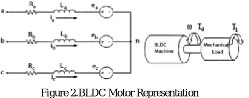
Mathematical modeling of a BLDC motor can be derived as similar manner as a brushes DC machine, where there have two equivalent circuits, i.e. electrical and mechanical equations. Figure 1 shows the basic building blocks of BLDC motor that contains three-phase stator circuit and mechanical part. Note that, the main different of BLDC machine to that of brushes DC motor is the construction of the machine where the BLDC motor has three phase windings at the stator (with n number of poles) and the rotor equipped with permanent magnet which is positioned at the center of the motor by the bearing. In such case, the rotor is not electrically connected to the stator that prevents the arcing phenomena which causes production of carbon and hence insulation failure.
Figure 2.BLDC Motor Representation
Figure 2.Three Phase Brushless D.C motor equivalent circuit model and mechanical model
For simplification, the electrical model is expressed for one phase of stator winding, e.g. phase k (k = a,b or c) as given by (1).
= + (1) where,
vkn(t) = instantaneous of k-phase voltage ik (t) = instantaneous of k-phase current
ek (t) = instantaneous of k-phase back-emf voltage Rk = k-phase resistance Lk = k-phase inductance .
On the other hand, the mechanical model of BLDC machine actually represents the production of torque as given by (2).
(2) where,
ω(t) = rotor angular velocity
B = viscous friction
J = moment of inertia
It should be noted that the production of torque is the summation of the torque produced for each phase; (3)
The production of torque and back-emf voltage for each phase are calculated as; , .,
(4)
(5)
where, the torque factor kT,k ( ϴ ) can be assumed equivalent to the back-emf voltage factor kV,k( ϴ ). The angular
velocity (ωe) is multiplication of rotor angular velocity and number of poles of the machine, i.e. ω x number of poles.
For trapezoidal operated in BLDC motor, the kT,k( ϴ ) and kV, k( ϴ ) are not constant as opposed to the constant field operated in brushes DC motor.
V.PRINCIPLE OF TORQUE HYSTERESIS CONTROLLER
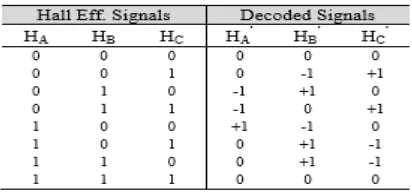
It is desirable to provide current limitation and fast torque dynamic control for many electric drive applications. A simple method that can offer these requirements is the use of torque hysteresis controller (THC) technique. Figure 3 shows the structure of torque hysteresis controller for BLDC motorThe control of torque can be established by controlling the three-phase current at its reference such that it will satisfy the equations (3) and (4). As shown by Fig. 3, the motor currentsneed to be controlled satisfying to their references (ia*, ib* and ic*). The generations of reference currents are based on the torque demand (i.e. Iref = Te,ref x G1) and decoded signals (HA’, HB’ and HC’) which are derived from the Hall Effect signals (HA, HB and HC) as given in Table 1.
Table 1.Derivation of Decoded signals effects on hall effect senor
Each phase current is controlled using a 2-level hysteresis comparator, which is responsible to produce appropriate switching status to be fed into the inverter, either to increase or decrease the phase current such that its error (or current ripple) is restricted within the hysteresis band (HB). In such a way, the reference current for each phase will have the same pattern waveform with the respective decoded signals.
VI. PROPOSED CURRENT BLOCKING STRATEGY
Figure 3.Structure of Torque Hysterisis Controller (THC) drive for brushless DC(BLDC) motor
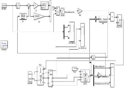
VII.MODELING OF TORUE HYSTERISIS CONTROLLER BY USING SIMULINK
Figure 4. Modelling of BLDC motor with Torque hysteresis controller
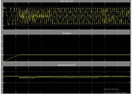
VIII.SIMULATION RESULT
Figure 6.Simulink results with Torque Hysteresis Controller
Figure 7.Simulink results with Torque Hysteresis Controller
IX.CONCLUSION
This paper has presented the modelling and simulation of torque hysteresis controller for BLDC motor in which comparison between with and without torque hysteresis controller work done . The ripple can minimize by using torque hysteresis controller at any load condition .Moreover, a new current blocking strategy to prevent the energy wastage from the batteries such that it can prolong the capacity of voltage battery is proposed. From the simulation results obtained, it showed that the hysteresis controller can offer inherent current protection/limitation and robustness in controlling the motor torque.
REFERENCES
[1] Yong Liu, “Direct Torque Control of Brushless DC Drives With Reduced Torque Ripple” IEEE TRANSACTIONS ON INDUSTRY APPLICATIONS, VOL. 41, NO. 2, MARCH/APRIL 2005.
[2] Kamalapathi.K1, Vinod Kumar.P2, Balaji.C3, “ TORQUE CONTROL OF BLDC MOTOR DRIVE USING MATLAB/SIMULINK ” International Journal of Emerging Trends in Engineering Research (IJETER), Vol. 3 No.6, Pages : 448 - 452 (2015) Special Issue of NCTET 2K15 - Held on June 13, 2015 in SV CollegeofEngineering,Tirupati http://warse.org/IJETER/static/pdf/Issue/NCTET2015sp80.pdf
[3] Ahmad Faiz Noor Azam , “TORQUE HYSTERESIS CONTROLLER FOR BRUSHLESS DC MOTOR DRIVES” Power and Energy Conversion Symposium (PECS 2012) Melaka, Malaysia 17 Dec 2012
[4] Mr.P.Nagasekhar Reddy , “ Modeling and Analysis of PI Controller Based Speed Control of Brushless DC Motor Drive” . INTERNATIONAL JOURNAL OF ENGINEERING SCIENCES & RESEARCH TECHNOLOGY,Reddy, 2(9): September, 2013.