Dtesting and Analysis of Weld Bead Profile of
TIG Welded Duplex Stainless Steel by Using
Taguchi Method
I.Stanly Ebenezer 1, K.Suriya1, S.Subash1 , R.Suthan1, P.Sathishkumar 2
U.G. Student, Department of Mechanical Engineering, Francis Xavier Engineering College, Vanarpettai, ,Tirunelveli,
Tamil Nadu , India1
Associate Professor, Department of Mechanical Engineering, Francis Xavier Engineering College,Vanarpettai,
Tirunelveli, Tamil Nadu, India2
ABSTRACT: The aim of the project is to study the effects of TIG welding on Duplex Stainless Steel welds. The aim
of the project is to study the effects of Tungsten Inert Gas Welding (TIG) on duplex stainless steel (DSS). Here butt joint is done on this type of welding. The weld bead is cut it in a transverse manner. The weld bead geometry is finally measured that is hardness and the percentage of ferrite. Using TIG welding butt type of joint is usually preferred for DSS. Weld bead geometry has great influence on mechanical strength. Welding speed, current and gap flow rate are some of the parameters which influence the welding process. Then the experiment is done by using. Taguchi method. Duplex stainless steel is a common structural material in the oil and gas industries, and has special applications in chemical, wastewater and marine engineering fields. The fabrication of metal structures requires the extensive use of TIG welding process welds. Generally, the single pass Tig welding with argon as shielding gas is limited to a 1.5 mm depth for the butt joint of stainless steels. One of the most notable techniques is to use activating flux with TIG welding to achieve single pass weld. If the weld current increases or the travel speed decreases, the weld bead becomes excessively wide with relatively little gain in the penetration capability. Therefore, it is necessary to improve the penetration capability and manufacturing productivity of TIG welding. TIG welding process are conducted for similar materials of 6mm thickness plates. The duplex stainless steel joined using automatic TIG welding machine. Single pass, autogenous, bead on plate TIG welds were made along the center line of the test specimens. A water cooled thoriated tungsten electrode rod with 45 degree angle
.
KEYWORDS:Tig Welding , Welding geometry, Taguchi method.
I.INTRODUCTION
TUNGSTEN INERT GAS (TIG WELDING)
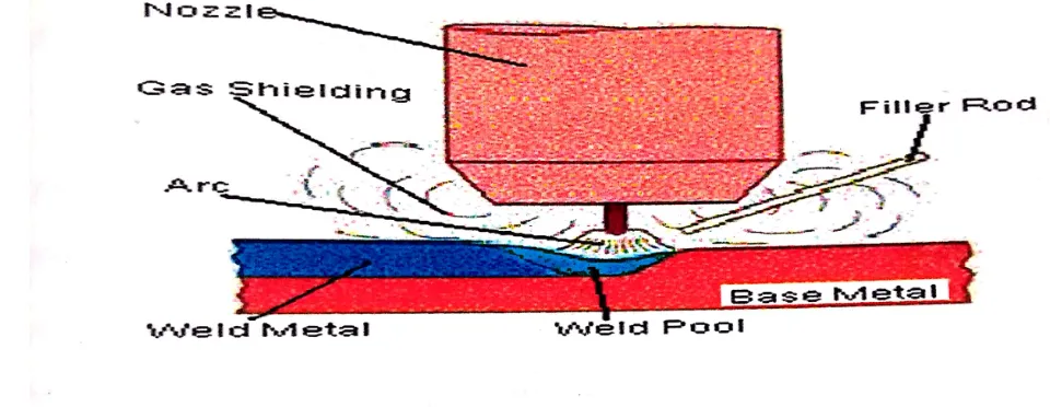
Figure 1- TIG Weld Area
Energy is supplied by a constant-current welding power supply and the end result is a conduction of highly-ionized gas and metal vapors (also known as plasma) across the welding arc. This energy is then transmitted over the arc, which forms a weld pool that connects the two metal pieces together.
II. WORKING
TIG welding is a welding process that uses the heat produced by an electric arc created between non consumable tungsten electrode and the weld pool. This electric arc is produced by the passage of current through a conductive ionized inert gas that also provides shielding of the electrode, molten weld pool and solidifying weld metal from contamination by the atmosphere.
The process may be used with or without the addition of filler metal using metal rods. Basic TIG welding process shown in fig4.
Fig 4 TIG Welding Process
1.1 EQUIPMENT IN TIG WELDING MACHINE
Power sources
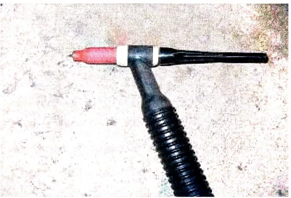
TIG torch
Regulators
Shielding gas
Power Sources
The preferred polarity of the TIG system depends largely the type of metal being welded. Direct current with a negatively charged electrode is often employed when welding steels, nickel, titanium, and other metals. The negatively charged electrode generates heat by emitting electrons which travel across the arc, causing thermal ionization of the shielding gas and increasing the temperature of the base material, and this can allow oxides to build on the surface of the weld. A TIG power source can be of the AC or DC types.
The principle of electric circuits will apply to only DC power sources. This means 70% of the heat is always on the positive side.
TIG Torch
The automatic and manual torches are similar in construction, but. Air cooling systems are most often used for low current operations up to about 200A, while water cooling is required for high current welding up to about 600A.
The torches are connected with cables to the power supply and with hoses to the shielding gas source and where used, the water supply. The internal metal parts of a torch are made of hard alloys of copper or brass in order to transmit current and heat efficiency. Ports around the electrode provide a constant flow of shielding gas. Collets are sized according to the tungsten electrode and to hold the electrode.
Regulator
A welding regulator is necessary to monitor the flow of shielding gas to the welding puddle. Gas must come out smoothly and controlled the welding arc. If you were to skip the regulator and hook up a hose directly to pressurized gas bottle, the gas could be released entirety in seconds. The regulator does just what it sounds like, it regulates the gas flow.
The pressure can then be set to usable and less wasteful level. The rate of flow can be adjusted by twisting a knob one way or the other to increase or decrease flow. Most TIG welding regulators will have two gauges which is shown in fig6 one to show the flow rate, the other to show the gas bottle pressures.
The gas bottle pressure reading will let you know how much gas is left in the bottle. As the gas is used, as the gas is used, the pressure will drop and the reading on the gauge will thus indicate.
TIG ARC
In D.C TIG welding, the tungsten electrode is usually connected to the negative polarity and the work piece to the positive polarity. According to the theory of electrons, the negatively charged electrons and the positively charged ions will migrate, when the arc is ignited.
The negative pole and approximately 70% to the work piece is connected to the positive pole.
Shielding Gas
As with other welding processes such as gas metal arc welding to protect the welding area from the atmospheric gases such as nitrogen and oxygen, which can cause fusion defects, porosity, and weld metal embrittlement if they come in contact with electrode ,the arc, or the welding metal. The gas also transfers heat from the tungsten electrode to the metal, and it helps start and maintain a stable arc. The selection of a shielding gas depends on several factors, including the type of material being welded, joint design, and desired final weld appearance. Argon is the most commonly used shielding gas for GTAW. Shielding gas mixture, argon hydrogen, is used in the mechanized welding of light gauge stainless steel, because hydrogen can cause polarity, its uses are limited. Similarly nitrogen can sometimes be added to argon helping to stabilize the austenite stainless steels and increase penetration when welding copper.
Electrode
An electrode in an electrochemical cell is referred to as either an anode or a cathode. The anode is now defined as the electrode at which electrons leave the cell and oxidation occurs, and the cathode as the electrode at which electrons enter the cell and reduction occurs. Each electrode may become either the anode.
III. LITERATURE REVIEW
Tsann-Shyi Chern, Kuang-Hung Tseng and Hsien-Lung Tsai (2010)
investigated the effects of the specific fluxes used in the tungsten inert gas(TIG) process on surface appearance, weld morphology, angular distortion, mechanical properties, and microstructures when welding 6mm thick duplex stainless steel. The applied flux increases the heat input therefore, there is an increase in the peak temperature of the weld metal and a reduction in the cooling rate. TIG weld metal produced using Sio2 flux possessed microstructures consisting of equal proportions of ferrite (52.3%) and austenite (47.7%) at room temperature. In this study, grade 2205 stainless steel TIG welding with Sio2 flux produced a full joint penetration and the greatest weld depth-to-width ratio. As a result, the angular distortion value was almost zero.
G. Ru”ckert, B. Huneau, S. Marya (2006)
the performance of silica coating on tig welding of AISI304L stainless steel by investigating the effect of coating geometry and thickness on weld penetrations. Two coating design technique were used, one is 20 mm wide continuous coating across the weld zone and second design technique is two parallel coatings 2mm apart around the joint. Activating flux mixing water and acetone or alcohol decides the particle size of the powder. Coating thickness will increase the penetration capability at their current level. This study investigates the design of fluxcoating. The optimized thickness in ATIG is observed to vary between 40 and 70 µm depending on the welding current.
S.C. Juang, Y.S Tarang (2002)
about the selection of process parameters for obtaining an optimal weld pool geometry in the TIG welding of S304 stainless steel plates with thickness of 1.5mm. Modified Taguchi method is adopted to analyze the effect of each welding process parameter on the weld pool geometry (front height, back height, front width, and back width). 3D-hommelewerk profilometer used to measure quality characteristic as lower the better adopted. Process parameter of arc gap, flow rate, welding current and welding speed are affecting the multiple quality characteristics.
Kuang-Huang Tseng, Nai-Shein Wang (2013) evaluated the potential of using gas tungsten arc welding assisted by FeS/FeF2 mixtures to improve joint penetration and weld quality in joining 316L stainless steel plates. The differences in surface appearance, geometric shape, and out of plane deformation of the elements made by using conventional and activated gas tungsten arc welding processes have been compared. The present study used mixtures of iron (ii), sulfide (FeS) and iron (ii) fluoride (FeF2) to systematically investigate the influence of specific components on the surface appearance, geometric shape, and out of plane deformation of the activated gas tungsten arc weldment. Author explored the application of GTA welding assisted by mixed compounds not only to increase joint penetration but also to improve the weld quality of stainless steel.
M.. Yousefieh, M. Shanmanian, A. Saatchi (2010)
It investigated corrosion resistance of super duplex stainless steel using pulsed current gas tungsten arc welding. Taguchi method was adopted to optimize the parameters of pulsed current gas tungsten arc welding. Among the parameters pulsed current was the most affecting parameter on corrosion resistance. Taguchi design experiment details and procedure are reviewed in this study.
V. Muthupandi , P. Bala Srinivasan, S.K. Seshadri, S. Sundaresan (2003) discussed the excellent combination of
strength and corrosion resistance in duplex stainless steels. This is due to their strict composition control and micro structural balance. To achieve the desired ferrite/austenite balance and hence properties, either the weld metal composition and the heat input is controlled. TEM studies, vicker hardness, charpy impact test were performed in this study. Nickel is very effective in controlling the ferrite/austenite ratio than the cooling rate for the range of composition studied.
IV.EXISTINGMODELINKUNDANPIPES
EXPERIMENTAL WORK
The rectangular specimens with length 250 mm, width 100 mm and thickness 6mm of duplex stainless steels are joined using TIG welding machine. TIG welding electrode was made by tungsten. The experiment was conducted only for a single experiment of TIG. Complete penetration has obtained at current (250 A), welding speed (100 mm/min) and gas flow rate (15 I/min). Fig 3.2 shows the welding process
DESIGN OF EXPERIMENT
The investigation of this study is to find the effect of TIG welding on tensile strength. The material selected is duplex stainless steel. By designing the experiment with the help of traditional or classical approach a lot of experiments have to be performed and it is a tedious process which leads to wastage of time and money, taguchi design is adopted. Taguchi method is systematic approach to design and analyze experiments for improving the quality characteristics. The parameter design based on the taguchi method can optimize the quality charaeristics through the settings of the
process parameter values.
Taguchi uses a special design of orthogonal array to study the entire parameter space with a small number of experiments.
The experimental results are then transformed into s/n ratio. The s/n ratio can be used to measure the quality characteristics deviating from the desired values.
And there are usually 3 characteristics higher the better; nominal the best lower the better for the static problem. For the dynamic problem. Slope and linearity are involved.
Finally a statistically level of ANNOVA is performed to see which process parameters are statically significant and based on the above analysis a confirmation experiment is made to verify the optimal process parameters, obtained from the parameter design.
The major steps required for the experimental design using taguchi method are
Establishment of objective function,
Identification of the factors and their levels,
Selection of an appropriate orthogonal array,
Experimentation,
Analysis of the data and determination of the optimal levels,
V. RESULTS AND DISCUSSION REGARDING TIG WELDING BY USING TAGUCHI METHOD
STEP-1
IDENTICATION OF FACTORS AND THEIR LEVELS
Table- 5.1
SI.NO FACTORS UNIT LEVEL1 LEVEL2 LEVEL3 LEVEL4
1 Current A 220 230 240 250
2 Welding speed Mm/min 100 110 120 130
3 Gas flow rate I/min 10 12 14 16
MECHANICAL PROPERTIES OF TIG WELDING
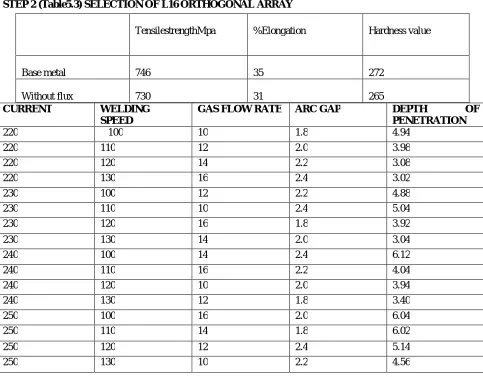
STEP 2 (Table5.3) SELECTION OF L16 ORTHOGONAL ARRAY
CURRENT WELDING
SPEED
GAS FLOW RATE ARC GAP DEPTH OF
PENETRATION
220 100 10 1.8 4.94
220 110 12 2.0 3.98
220 120 14 2.2 3.08
220 130 16 2.4 3.02
230 100 12 2.2 4.88
230 110 10 2.4 5.04
230 120 16 1.8 3.92
230 130 14 2.0 3.04
240 100 14 2.4 6.12
240 110 16 2.2 4.04
240 120 10 2.0 3.94
240 130 12 1.8 3.40
250 100 16 2.0 6.04
250 110 14 1.8 6.02
250 120 12 2.4 5.14
250 130 10 2.2 4.56
STEP 3
ANALYSIS AND CALCULATION OF S/N RATIO, AND GRAPH DISCUSSIONS
All the parametric design parameter and their values are converted to statistical data that is signal to noise ratio.
It is to analyze which parameters are significant and which would affect the depth of penetration and ferrite content and which influence the welding processes.
This is the use of calculating s/n ratio. The analysis and calculation of s/n ratio is briefly discussed in the following table which are listed as follows
TensilestrengthMpa %Elongation Hardness value
Base metal 746 35 272
EXPERIMENT CURRENT WELDING SPEED
GAS FLOW RATE
ARC GAP
DEPTH OF
PENETRATION
S/N RATIO
1 220 100 10 1.8 4.94 13.8745
2 220 110 12 2.0 3.98 11.9977
3 220 120 14 2.2 3.08 9.7710
4 220 130 16 2.4 3.02 9.6001
5 230 100 12 2.2 4.88 13.7684
6 230 110 10 2.4 5.04 14.0486
7 230 120 16 1.8 3.92 11.8657
8 230 130 14 2.0 3.04 9.6575
9 240 100 14 2.4 6.12 15.7350
10 240 110 16 2.2 4.04 12.1276
11 240 120 10 2.0 3.94 11.9099
12 240 130 12 1.8 3.40 10.6296
13 250 100 16 2.0 6.04 15.6207
14 250 110 14 1.8 6.02 15.5919
15 250 120 12 2.4 5.14 14.2193
16 250 130 10 2.2 4.56 13.1793
The above graph is plotted based on the calculation of s/n ratio and their appropriate parameters. Our assumption should be taken as the larger the better value.
1. From the welding speed versus mean of s/n ratio graph it is proved that when the welding speed increases the value of S/N ratio gradually decreases.
2. From the gas flow rate versus mean of s/n ratio graph it is proved that when the gas flow rate increases the value of s/n ratio first decreases and then maintained constant at sometime and then decreases.
3. From the arc gap versus mean of s/n ratio graph it is proved that when the arc gap increases the value of s/n ratio first decreases and then maintained constant at some time and then again increase.
STEP 4
OPTIMISED PARAMETERS AND THEIR LEVELS IN TERMS OF S/N RATIO Table 5.6
LEVEL CURRENT WELDING SPEED GAS FLOW RATE ARC GAP
1 11.31 14.75 13.25 12.99
2 12.34 13.44 12.65 12.30
3 12.60 11.94 12.69 12.21
4 14.65 10.77 12.30 13.40
CALCULATION OF OPTIMIZED PARARMETER IN TERMS OF S/N RATIO
The optimized parameters and their levels in terms of s/n ratio are tabulated. It is calculated based on the previous table. By calculating the average value at each parameter at each level the optimized parameters are listed. By our assumption the larger value should be taken as the better value.
So the larger one is considered as the standard optimized one. So the optimized parameter level is 1. Current-250 amps
2. Welding speed-100mm/min 3. Gas flow rate- 101/min 4. Arc gap- 2.4mm.
STEP5
ANOVA TABLE PERFORMANCE
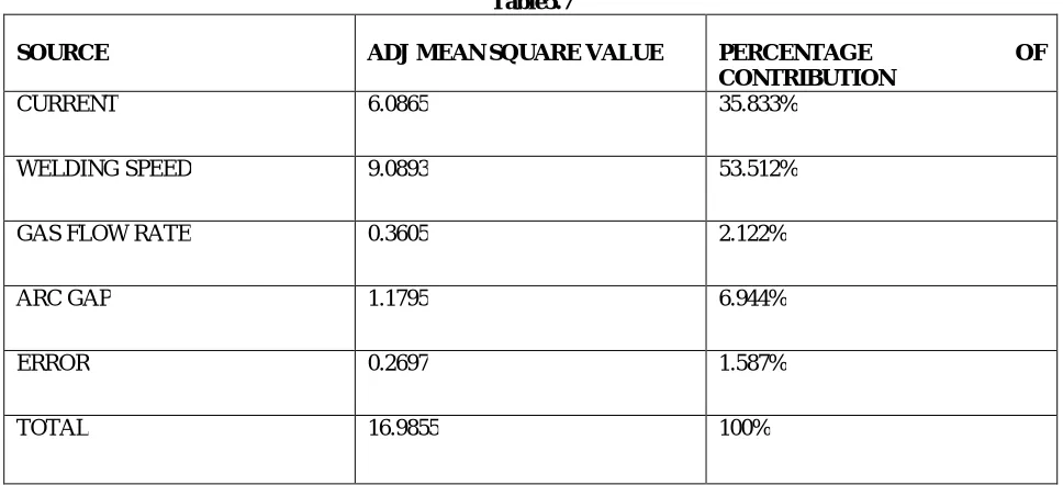
Table5.7
SOURCE ADJ MEAN SQUARE VALUE PERCENTAGE OF
CONTRIBUTION
CURRENT 6.0865 35.833%
WELDING SPEED 9.0893 53.512%
GAS FLOW RATE 0.3605 2.122%
ARC GAP 1.1795 6.944%
ERROR 0.2697 1.587%
CALCULATION OF PERCENTAGE OF CONTRIBUTION 1. CURRENT=(ADJ MS/TOTAL)*100=35.833%
2. WELDING SPEED=(ADJ MS /TOTAL)*100=53.512% 3. GAS FLOW RATE=(ADJ MS/TOTAL)*100=2.122% 4. ARC GAP=(ADJ MS/TOTAL)*100=6.944%
5. ERROR=(ADJ MS/ TOTAL)*100=1.587%
STEP 6
REGRESSION ANALYSIS BY PREDICTIVE METHOD
Regression analysis is a technique for finding the depth of penetration theoretically.
Before finding the depth of penetration experimentally by using video measuring system we can find the depth of penetration theoretical value must almost near or equal to the experimental value. By this way can check whether our experiment goes in a right path. The generational regression equation is explained as follows.
Y=b0+b1x1+b2x2+b3x3+b12x12+b13x13+b23x23+b11x1²+b22x2²+b33x3² Where b0=constant coefficient
B1= clamping pressure b2=amplitude of vibration b3=weld time
Where x1, x2, x3 are the regression coefficients.
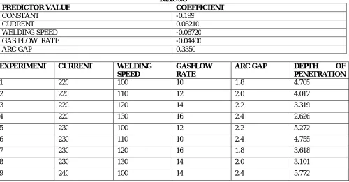
The coefficients of the regression equation are determined using Minitab 15.0 software. The regression equation is depth of penetration = -0.20+ 0.0521
CURRENT -0.0672 WELDINGSPEED -0.0440 GASFLOW RATE +0.335 ARCGAP. The table is listed as follows
Table 5.8
PREDICTOR VALUE COEFFICIENT
CONSTANT -0.199
CURRENT 0.05210
WELDING SPEED -0.06720
GAS FLOW RATE -0.04400
ARC GAP 0.3350
EXPERIMENT CURRENT WELDING
SPEED
GASFLOW RATE
ARC GAP DEPTH OF
PENETRATION
1 220 100 10 1.8 4.705
2 220 110 12 2.0 4.012
3 220 120 14 2.2 3.319
4 220 130 16 2.4 2.626
5 230 100 12 2.2 5.272
6 230 110 10 2.4 4.755
7 230 120 16 1.8 3.618
8 230 130 14 2.0 3.101
10 240 110 16 2.2 4.945
11 240 120 10 2.0 4.47
12 240 130 12 1.8 3.643
13 250 100 16 2.0 6.071
14 250 110 14 1.8 5.42
15 250 120 12 2.4 5.037
16 250 130 10 2.2 4.386
VI.CONCLUSION
In this present work, DUPLEX STAINLESS STEELS 2205 are taken as the base materials for joining to occur through TIG welding process. The TIG welding resulted in inferior mechanical properties of the welds. Hence the present work, a design of experiment technique, the taguchi method has been used to optimize the TIG welding parameters (current, welding speed, gas flow rate) for the tensile strength of duplex stainless steel. Microstructure studies have been carried out on welded specimen. The following conclusions are drawn from this work.
In this study 6mm thick DUPLEX STAINLESS STEELS 2205 PLATES were successfully welded using TIG welding using TIG welding machine.
TIG welding of DUPLEX STAINLESS STEEL 2205 was investigated with different process parameters and also developed the design matrix to optimize process parameters.Microstructure study was carried to reveal that ferrite phase of the welded duplex stainless steel 2205 higher than base material due to recrystallization
Microstructure study was carried to reveal that ferrite phase of the welded duplex stainless steel 2205 higher than base material due to re crystallization.
REFERENCES
1. G.Ru”ckert , B. Huneau, S. Marya, “ optimizing the design of silica coating for productivity gains during the TIG welding of 304L stainless steel”, journal of materials and design, Vol. 28, pp. 2387-2393,2007.
2. Hidetoshi fujii , Toyoyuki sato . shnping lua, Kiyoshi Nogi,” development of an advanced A-TIG (AA-TIG) welding method by control of marangoni convection”, journals of materials science and Engineering, Vol. A495, pp. 296-203, 2008
3. Iris Alvarez-Armas,” duplex stainless steel: brief history and some recent alloys”, recent patents on mechanical engineering, Vol. 1, pp. 51-57,2008.