ISSN (Print) : 2347 - 6710
I
nternationalJ
ournal ofI
nnovativeR
esearch inS
cience,E
ngineering andT
echnology Volume 3, Special Issue 3, March 20142014 International Conference on Innovations in Engineering and Technology (ICIET’14) On 21st & 22nd March Organized by
K.L.N. College of Engineering, Madurai, Tamil Nadu, India
Grid Synchronization by Estimation of
Positive Sequence Component in Three Phase
Signals
S.Manoharan, Dr.K.Gnanambal
, R .Girija, K.P.Ram Prasath
Department of Electrical and Electronics Engineering, K.L.N College of Engineering, Madurai, India Department of Electrical and Electronics Engineering, K.L.N College of Engineering, Madurai, India
Department of Electrical and Electronics Engineering, K.L.N College of Engineering, Madurai, India.
Department of Electrical and Electronics Engineering, K.L.N College of Engineering, Madurai, India
ABSTRACT— Distributed Generation (DG) System is a small scale electric power generation which is based on wind energy, fuel cell, photo voltaic system, hydro etc. Grid Synchronization is one of the most important issues in the control of inverters connected to the grid. The proper operation of grid connected inverter system is determined by grid voltage conditions such as phase, amplitude and frequency. A discrete phase-locked loop (PLL) is used to track the phase angle in order to improve the synchronization systems response in adverse grid conditions. Using the enhanced synchronization structure the fundamental positive-sequence component of grid voltages in asymmetric and distorted three-phase systems is estimated. The α-β stationary frame is used to obtain the pulsation for grid inverter using a space vector pulse width modulation (SVPWM). The performance of the proposed structure is verified through simulations using a grid set of ideal and non-ideal grid conditions (three-phase voltage unbalance, variation in frequency, variation in amplitude and phase shift).The simulation results demonstrates that the proposed method is very effective in digital structure synchronization .
KEYWORDS— Distributed Generation (DG), discrete phase-locked loop (PLL), synchronization systems, positive-sequence component, SVPWM, non-ideal grid conditions.
I. INTRODUCTION
The Distributed Generation (DG) systems are highly sporadic power generation system and their power output depends heavily on the natural conditions. Various grid code requirements must be met to connect the DG systems with the utility grid. To ensure safe and reliable operation of power system based on DG system [1], usually power plant operators should satisfy the grid code requirements such as fault ride through, power quality improvement, grid synchronization, grid stability and power control etc.
The grid synchronization techniques can be adversely affected by the application of a disturbing influence (influence quantity) on the electrical input signals. Due to the increase in number of Distributed Generation (DG) Systems has lead to complexity in control while integrating into grid. As a result requirements of grid connected inverters become stricter and stricter to meet very high power quality standards.
Grid voltage conditions such as phase, amplitude and frequency determine the proper operation of a grid connected system. In such applications, a fast and accurate detection of the phase angle, frequency and amplitude of the grid voltage is essential. These factors, together with the implementation simplicity and the cost are all important when examining the credibility of a synchronization scheme. Therefore an ideal phase-detection scheme must be used to promptly and smoothly track the grid phase through various short-term disturbances [2] [3] and long term disturbances to set the energy transfer between the grid and the power converter.
One of the earliest methods used for tracking the phase angle is Zero Crossing Detector (ZCD) method [4], but the performance of ZCD is badly affected by power quality phenomena [5]. The Linear PLL is mainly used to detect phase for single phase supply. Use of voltage controlled oscillators (VCOs) resulted in more rigid controllers such as the Phase Locked Oscillator systems and the Charge-Pump PLLs. However
with the development of discrete devices such as
microcontrollers, various high performance synchronization methods have been introduced.
Synchronous reference frame–phase-locked loops (SRF-s) are the most widely used systems for synchronizing signals [14].
A fast and accurate estimation of fundamental positive-sequence component [15] of grid voltage is essential for different applications involving FACTS, power devices and grid connected power converters. It is essential to estimate for both monitoring and control in order to satisfy grid codes, and to obtain high performance response.
This paper proposes an enhanced synchronization structure based on PLL and fundamental positive-sequence components which is used to synchronize the component of grid voltages in three-phase systems that can include distorted and asymmetric voltage terms. Finally, the performances of the digital synchronization structure are investigated in the presence of both ideal and non-ideal grid conditions such as amplitude variation, frequency variation, phase jump and improper phase shift. The analysis is carried out in MATLAB/SIMULINK environment and the obtained results are discussed for effectiveness of the study.
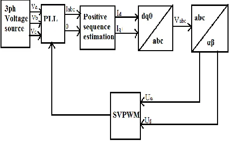
II.OVERVIEW OF PROPOSED SYSTEM
A. Synchronous reference frame based PLL
A phase-locked loop is a control system that generates an output signal whose phase is related to the phase of an input "reference" signal [5]. Frequency is the time derivative of phase. Keeping both the input and output phase in lock step implies keeping the input and output frequencies in lock step. Consequently it can track an input frequency or it can generate a frequency that is a multiple of the input frequency.
At present Synchronous Reference Frame PLL (SRF-PLL) is the one of the most employed PLL topology. If the single-phase voltage input Vα, is an internally generated signal that is a 90 degrees shifted version of Vβ .The transformation blocks as shown in fig. 1 changes the reference frame, bringing the voltages system from an α-β stationary reference frame to a d-q rotating synchronous reference frame.
The feedback loop controls the angular position of this d-q reference frame. In particular the utility voltage vector is totally lined up to the axis. In this way it coincides with all its q-component; consequently the d-component is made equal to zero. The q-component describes the voltage vector amplitude course.
After studying the various Phase Locked Loop schemes used today in modern power system, we observe that the Synchronous Reference Frame PLL method provides a simple yet effective way to measure the phase angle. In case of a single phase system we obtain the quadrature signal by delaying the available sinusoid or adopting some other similar structure, however in 3 phase system this problem is greatly reduced due to the availability of three phase shifted signals. Hence by using arithmetic manipulation we obtain the required orthogonal signal necessary for SRF-PLL implementation.
B.Fundamental positive-sequence component:
relevant disturbances such as voltage imbalance, frequency deviation, phase jumps and improper phase shifts.
C.Space vector pulse width modulation:
It is used for the control of pulse width modulation. To implement space vector modulation a reference signal is sampled with fundamental frequency. The reference signal needed is generated from the Clarke transformation from three phase
voltage source.
Fig. 1 Synchronization system structure.
III.PROBLEMFORMULATION
The operation of the proposed synchronized structure is implemented by considering three phase supply voltage source Va, Vb and Vc. In order to track the phase angle a discrete three phase PLL is used. It controls the internal voltage source. The output consists of estimated phase synchronous angle θ and (sin θ, cos θ) for the dq transformation blocks. In steady state sin θ will be in phase with the fundamental positive sequence of the α-component. The PLL also measures the frequency and generates a signal ωt locked on the variable frequency of system voltage. The sin θ, cos θ values estimated using the PLL are used to obtain d, q and zero components using Park transformation.
)) 3 / 2 sin( ) 3 / 2 sin( sin ( 3 /
2
V t V t V t
Vd a b c
(1) )) 3 / 2 cos( ) 3 / 2 cos( cos ( 3 /
2
V t V t V t
Vq a b c
(2)
)
(
3
/
1
0
V
aV
bV
cV
(3)Copyright to IJIRSET www.ijirset.com 589
Fig. 2 Simulation model for positive sequence estimation.
A SVPWM is used to obtain the pulsation for the DC-AC inverter with Uα and Uβ as the reference signal obtained by using Clark transformation.
)
5
.
0
5
.
0
(
*
3
/
2
Va
Vb
Vc
U
(4))
*
2
/
3
*
2
/
3
(
*
3
/
2
Vb
Vc
U
(5)IV.RESULTSANDDISCUSSION
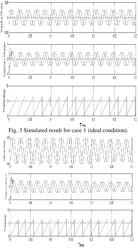
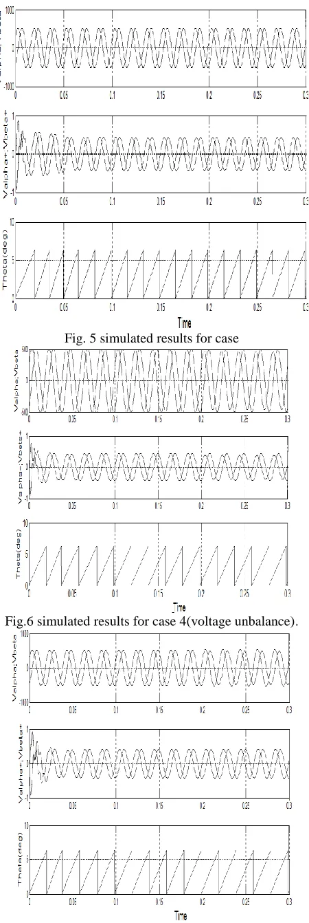
To verify the effectiveness of the proposed synchronization system structure, some significant cases have been simulated are performed using Matlab-Simulink software.
The main objective is to estimate the fundamental positive-sequence component from the three phase supply voltages which contains distortion asymmetries. The fundamental grid frequency is 50 Hz and the sampling frequency used is 5kHz.
1)
Case test-1: The proposed structure is initially tested with ideal condition without considering any distortion. The grid positive sequence voltage is set as 295.2) Case test-2: A three-phase voltage unbalance is applied with a voltage reduction of 50V in each phase.
3) Case test-3: A three-phase frequency unbalance is produced by a variation of 5 Hz from the fundamental grid frequency of 50 Hz.
4) Case test-4: The amplitude is varied by 50V in phase-A of the grid supply voltage.
5) Case test-5: Improper phase-shift is produced by having constant frequency but not the proper phase shift of 120° relative to each other. A phase shift of 5°variation is applied to the balanced three phase voltage.
Waveforms presented in Figs. 3-7 show the simulated output for the cases described. All of the cases first include (top plot) the Vα and Vβ that corresponds to the grid voltages in the α-β frame. The central plots show the fundamental positive sequence grid voltages Vα+ and Vβ+ in the α-β frame. The bottom plots show the phase angle of the fundamental positive sequence of grid voltages.
Fig. 3 Simulated result for case 1 (ideal condition).
Fig. 5 simulated results for case
Fig.6 simulated results for case 4(voltage unbalance).
Different non-ideal conditions were simulated and most were handled well by the system. Unbalances in the three phase input signals were overall handled well by the system. The estimation of fundamental positive sequence component and phase angle tracking was performed well by the system. Although the system could handle the non-ideal cases fairly well it was sometimes slow.
V.CONCLUSION
In the process of synchronization of DG generated power with the utility, phase tracking is very essential for proper grid synchronization. A PLL can be used to obtain magnitude, frequency and phase information for estimation of fundamental positive-sequence component of grid voltage. Accurate and fast estimation of these quantities can be used for control and protection of the system. Overall the grid synchronization system based on positive-sequence estimation is able to handle non-ideal conditions well. The positive-sequence phase angle is tracked within acceptable margins and therefore the PLL system as given with the positive sequence estimation could indeed operate in a real life application.
ACKNOWLEDGMENT
The authors are grateful to the principal and management of K.L.N college of Engineering, Sivagangai for providing all facilities for the research work.
REFERENCES
[1] F. Blaabjerg, R. Teodorescu, M. Liserre, and A. V. Timbus, ―Overview of control and grid synchronization for distributed power generation systems,‖ IEEE Trans. Ind. Electron., vol. 53, no. 5, pp. 1398–1409,Oct. 2006.
[2] J. Svensson, ―Synchronisation methods for grid-connected voltage source converters,‖ Proc. Inst. Elect. Eng., vol. 148, no. 3, pp. 229–235,May 2001.
[3] M. Karimi-Ghartemani and M. Iravani, ―A method for synchronization of power electronic converters in polluted and variable-frequency environments,‖ IEEE Trans. Power Syst., vol. 19, no. 3, pp. 1263–1270, Aug. 2004.
[4] F. M. Gardner, Phase Lock Techniques. New York: Wiley, 1979. [5] Francisco D. Freijedo, Jesus Doval-Gandoy, Oscar Lopez, Carlos
Martinez-Penalver, Alejandro G. Yepes, Pablo Fernandez-Comesana, Andres Nogueiras, JanoMalvar, Nogueiras, Jorge Marcos and Alfonso Lago, ―Grid-Synchronization Methods for Power Converters,‖ Proc. of IEEE 35th Annual Conference on Industrial Electronics, IECON 2009, pp. 522 – 529.
[6] FANG Xiong, WANG Yue, LI Ming, WANG Ke and LEI Wanjun, ―A Novel PLL for Grid Synchronization of Power Electronic Converters in Unbalanced and Variable-Frequency Environment,‖ Proc. of IEEE International Symposium on Power Electronics for Distributed Generation Systems: pp. 466-471, 2010.
[7] C. Lascu, L. Asiminoaei, I. Boldea, and F. Blaabjerg, ―High performance current controller for selective harmonic compensation in active power filters,‖ IEEE Trans. Power Electron., vol. 22, no. 5, pp. 1826–1835,Sep. 2007.
[8] M. Routimo, M. Salo, and H. Tuusa, ―Comparison of voltage-source and current-source shunt active power filters,‖ IEEE Trans. Power Electron.,vol. 22, no. 2, pp. 636–643, Mar. 2007.
Copyright to IJIRSET www.ijirset.com 591
[12] T. Ahmed, K. Nishida, and M. Nakaoka, ―A novel stand-alone induction generator system for AC and DC power applications,‖ IEEE Trans. Ind Appl., vol. 43, no. 6, pp. 1465–1474, Nov./Dec. 2007.
[13] H. Awad, J. Svensson, and M. J. Bollen, ―Tuning software phase-locked loop for series-connected converters,‖ IEEE Trans. Power Del., vol. 20, no. 1, pp. 300–308, Jan. 2005.
[14] A. Timbus, M. Liserre, R. Teodorescu, P.Rodriguez, and F. Blaabjerg, ―Evaluation of current controllers for distributed power generation systems,‖ IEEE Trans. Power Electron., vol.24, no. 3, pp. 654-664, Mar. 2009.