Implementation of Survivability by using
Networking, Switching and Routing
Techniques (SNSRT)
Mahantesh Patil1, K.V.S.S.S.S.Sairam2
P G Scholar, Dept. of Electronics and Communication Engineering,NMAMIT, Nitte, Udupi, Karnataka, India1
Professor, Dept. of Electronics and Communication Engineering,NMAMIT, Nitte, Udupi, Karnataka, India2
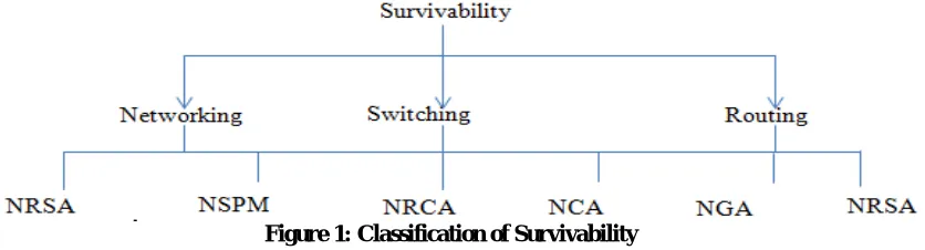
ABSTRACT:Survivability means protection against failure in an optical network. Networking gives the connectivity between two paths. Switching determines the transition between one state to another state. Routing signifies the path direction. Hence the combination of all the three namely networking, switching and routing will determine Network Survivability Restoration Algorithm (NSRA), Network Survivability Protection mechanisms (NSPM), Network Capacity Multiplexing Model (NCMM), Network Routing and Capacity Assignment (NRCA), Network Code Assignment (NCA), Network Graph Assignment (NGA), Network Survivability Path Parameters (NSPP).
KEYWORDS:Survivability, Switching, Routing, NSRA, NSPM, NCMM, NRCA, NCA, NGA, NSPP.
I. INTRODUCTION
In optical networks, each link carries a huge amount of traffic. Any network failure, like a link failure, would result in massive data loss and eventually a high revenue loss for the service providers. Therefore, survivability in optical networks is of prime concern, and has to be addressed with utmost importance. In a real time environment, network failures do occur hence, recovery from the failure, and restoration of services in the affected areas in the network is very important. The most prominent types of network failures are cable cuts and equipment failures. Fire and other catastrophic events also cause network failures. Cable failures have the highest occurrence in optical networks. Thus Survivability of optical network is very important and it is broadly classified into networking, switching and routing as shown in Figure 1.
II.LITRATURESURVEY
Dongyun Zhou et.al.,[1] explains Survivability is most important requirements of networks and defines as the ability of a network to withstand and recover from failures. The importance of survivability is magnified in fiber optic networks with throughputs is of the order of Gbps and Tbps.
Kavian et.al., [2] explains the survivability in optical networks is defined as the network’s resilience to failures. Survivability techniques are broadly classified as protection and restoration techniques. The term protection refers to reserving the network resources for survivability, whereas in restoration, no such reservation is made, and the backup path is calculated after the occurrence of failures. In optical networks, a single fiber can carry Tbps of data, and a fiber failure can cause huge loss of data and revenue with the quality of service severely affected. Therefore, survivability in optical networks is very important for network functioning. The layers operating above the optical layer have fully fledged protection schemes. But a single link failure in the optical layer may result in multiple connection failures in the top layers. Therefore, the process of protection and restoration in the optical layer is vital to the network’s survivability. The provision of survivability in the optical layer also has its own merits of speed, and efficiency to cope with failures.
In survivable optical networks, the Shared Risk Link Group (SRLG) refers to the group in which the links in a network share a common physical element, for example, a cable, a duct or a node. A single SRLG failure will result in the failure of all the elements that belong to the specific SRLG explained by Strand et.al., [3]. Survivability against SRLG failures in optical networks was studied by Zang et.al., [4] in which, only the static traffic is considered and the authors had described the formulation of shared path protection. As the number of shared risk link groups increases, it is very difficult to provide a 100% SRLG failure protection in practical networks.
Shao et.al., [5] proposed an approach in which the protection paths are selected in such a way that they share a least number of shared risk link groups with the working paths. The literature on protection in optical networks focused mainly on survivability issues, and the cost factors were not effectively considered. Therefore, in this work, the role of the topological parameters is investigated for dimensioning optical networks with protection, aiming at improved resilience and reduced cost.
Fumagalli et.al.,[6] explains the restoration methods can be either link based or path based. In link-based schemes, when a link failure occurs, the connections which are affected are rerouted around the failed link. Link based restoration performs the recovery over a failed link, by restoring all the associated light paths. In path based schemes, each affected connection is rerouted to a backup path, and not near the vicinity of the failed link discussed by Ramamurthy et.al.,[7]. The affected connections due to the failure are restored on a source to destination basis. In general terms, the path based schemes yield higher capacity efficiency while the link-based schemes result in shorter recovery times which is explained by Mohan et.al.,[8].
III.PROPOSEDWORK
Survivability Parameters:
Table 1: Survivability Parameters
Parameters Description
Type of Protection Single Protection path,
Multiple Protection path
Problem formulation:
Single path connectivity , multi path connectivity and Cross connectivity.
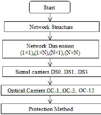
Proposed Algorithm
Determine all the paths in a given network and also ensure the shortest path.
Across each path survivability can be obtained in terms of network dimension.
Each network intern each path is assigned with Digital signal levels and also the optical carriers which
represents faithful transmission and reception
Apply the protection method whenever failure occur between source and destination.
Input:
Network graph Direct {D} and Indirect {ID} with signals and carriers in each path.
Output:
Protection ratio of network.
Protection Methods:
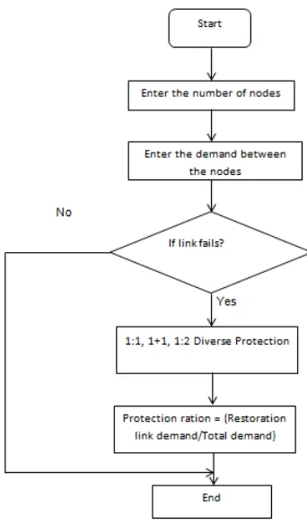
The protection methods such as 1:1, 1+1, and 1:2 Diverse protection are used. Whenever a link fails in a network the protection methods are applied. In 1:1 method consists of working path and protection path and when working path fails then the data is transmitted to the protection path. In 1+1 method the data is sent both in working and protection path and whenever link fails the destination node simply switches to protection path. In 1:2 Diverse protection the demand is reduced to half whenever the link fails and transmitted in diverse routes to reach the destination. The general flowchart of protection method is as shown in Figure 2. The flowchart for the protection method for a given network is as shown in Figure 3.
Flowchart:
Figure 3: Flowchart of Protection methods
Description:
Initially network consists of source ‘S’
While Direct and Indirect ≠ 0
a) Determine network least path connectivity from source to destinations.
b) Each signal with carrier carries the demand (cost).
c) By calculating each path information and updating the demand value through Direct and Indirect.
d) Update the network connectivity.
e) Calculate the protection ratio of the nework.
IV.RESULTS
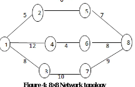
Figure 4: 8×8 Network topology
Table 2: Protection ratio of network
V.CONCLUSION
In this paper, an 8×8 network topology is taken and can be extended for N×N. The demands between the nodes is in terms of Digital Signal levels which carriers the information. The Protection ratio is calculated for 1:1, 1+1 and 1:2 Diverse Protection.
REFERENCES
[1] Dongyun Zhou and Suresh Subramaniam, “Survivability in Optical Networks” IEEE Network, Vol. 14, pp. 16-23,2000
[2] Kavian, Y.S., Rashvand, H.F., Leeson, M.S., Ren, W., Hines, E.L. and Naderi, M. “Network Topology Effect on QoS Delivering in Survivable DWDM Optical Networks”, Journal of Telecommunication and Information Technology, pp. 68-71, 2009.
[3] Strand, J., Chiu, A. and Tkach, R. “Issues for Routing in the Optical Layer”, IEEE Communication Magazine, Vol.39, pp.81-87, 2001. [4] Zang, H., Ou, C., and Mukherjee, B., “Path-protection Routing and Wavelength Assignment (RWA) in WDM Mesh Networks under ductlayer
constraints”, IEEE-ACM Transactions on Networking, Vol.11, No.2, pp.248-258, 2003.
[5] Shao, X., Zhou, L., Cheng, X., Zheng, W., and Wang, Y., “Best Effort Shared Risk Link Group (SRLG) Failure Protection in WDM Networks”, in Proc. IEEE Int. Conf. on Communication,pp.5150-5154, 2008.
[6] Fumagalli, A., Cerutti, I., Tacca, M., Masetti, F., Jagannathan, R., and Alagar, S., “Survivable Networks based on Optimal Routing and WDM Self-Healing Rings”, in Proc. Infocom, Vol.2, pp.726-733, 1999.
[7] Ramamurthy, S., and Mukherjee, B., “Survivable WDM Mesh Networks”, Journal of Lightwave Technology, Vol.21, No.4, pp.870-883, 2003. [8] Mohan, G., and Siva Ram Murthy, C., “Lightpath Restoration in WDM Optical Networks”, IEEE Network, Vol.14, No.6, pp.24-32, 2000.
Protection Technique
Protection Ratio %
1:1 100
1+1 100