Application of Multimode Single Leg
Converter in Power Electronic Technology
based Conversion System
Madhavi Gatty 1, Ajithanjaya M.K 2
PG-Student, Dept. of E&E, St. Joseph Engineering College, Vamanjoor, Mangalore, India1
Asst. Professor, Dept. of E&E, St. Joseph Engineering College, Vamanjoor, Mangalore, India2
ABSTRACT: Multimode power conversion system is proposed in this paper. This consists of multimode single leg converter which replaces bidirectional and boost converter. Proposed converter performs the function of boost as well as bidirectional converter there-by increasing system efficiency and fault tolerance capacity. Proposed converter has four modes of operation. These modes are simulated using SIMULINK. This power electronic technology can be applied to renewable & alternative energy generation systems (RAEGS) and electric vehicles (EV).
KEYWORDS: power conversion, bidirectional converter, electronic technology, SIMULINK.
I. INTRODUCTION
In recent years increasing prices of oil and natural gases made sources of energy such as wind, solar and fuel cells very attractive towards industrial fields. Energy conversion Technology based on Power electronics can be applied towards electric vehicles (EV) and renewable & alternative energy generation system (RAEGS). But in such systems we have to be very much concern about battery management because these systems require battery pack of high density for the operation of the components. System performance can be improved by the use of ultra capacitors which also reduces the battery stress and protects the battery. Generators, converters, inverters and battery are the main blocks of these systems and generally power conversion requires boost converter and power management requires buck- boost converter. To overcome this problem, multimode single leg converter is introduced in this paper which performs the power conversion with improved system efficiency. This converter has simple structure therefore diagnosis of problems are very easy. The proposed converter performs the function of both bidirectional and boost converter. SIMULINK is used to verify the performance characteristics of the proposed converter.
II. MULTIMODE SINGLE LEG CONVERTER
Configuration of power conversion system for RAEGS and EV is shown in figure 1(a) and it consists of generators, converters, inverters, battery or UC and loads.
Circuit diagram of proposed converter is presented in figure1 (b). This converter has two inductors, two switches, battery and a diode. In this converter, number of switches are also reduced hence loss is reduced which increases the efficiency of the conversion. Proposed converter functions as boost as well as bidirectional converter. Proposed converter operates in four modes.
They are (a) Mode1 where voltage supplied by the source is boosted up. Hence it is also called main boost mode. (b) Mode 2 in which supply voltage is boosted as well as battery also gets charged up and this mode is also named as boost –buck mode. (c) Mode3 performs boosting up of both supply voltage and battery voltage hence it is termed as boost-boost mode. (d) Mode4 is useful when input is insufficient to provide power to the load and load is supplied only by the stored charge in the battery. Hence this mode is called battery boost mode.
A. MODE 1: MAIN BOOST MODE
In this mode ON-OFF period for SW1 and SW2 is same. Switching pattern is shown in figure 2. When both the
switches are ON then inductor L1 current rises. There is no change in the battery charge. L1 ripple current is given by
ΔIL1= (Vs. Ton) (1)
L1
Figure 2: Mode1 Switching pattern.
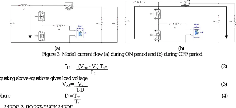
Current flows during ON- OFF period of SW1 and SW2 is described in figure 3(a) and 3(b). During OFF period both
the switches are OFF then inductor L1 current decreases and supply voltage along with inductor voltage is transferred to
the load. Now ripple current in the inductor is given by
(a) (b)
Figure 3: Mode1 current flow (a) during ON period and (b) during OFF period
ΔIL1 = (Vout - Vs) Toff (2)
L1
Equating above equations gives load voltage
Vout= Vs (3)
1-D
Where D = Ton (4)
(a) (b)
(c) (d)
Figure 4: Mode2 (a) Switching Pattern. Current flows during (b) Ton_boost (c) Ton_buck (d)Toff-buck
Switching pattern is shown in figure 4(a). During Ton_boost both the switches are ON which makes the inductor L1 to get
charged and stored charge is delivered to the load when SW2 is OFF. Current flows during this mode are shown in
figure 4(b), (c) and (d). During Tonbuck battery starts charging. Ripple current for inductor L1 is given by
ΔIL1= Vs. Tonboost
L1 (5)
Energy transfer to the load takes place when SW2 goes OFF. Ripple current is obtained as
ΔIL1= (Vout – Vs) Toff_boost (6)
L1
Output voltage is obtained by equating above equations
Vout = Vs (7)
1-Dboost
Where Dboost = Ton_boost (8)
Ts_boost
When SW2 is OFF during Ton buck, SW1 continues to be ON which makes the inductor L2 to get charged up and its ripple
current is given by
ΔIL2= (Vs– Vbattery) Ton_buck (9)
L2
During Ton_boost and Toff_buck inductor L2 current decreases .
ΔIL2= Vbattery. (Ton_boost + Toff_buck) (10)
L2
From equations (9) and (10) we get battery voltage
Vbattery = Vs. Dbuck (11)
Where Dbuck = Ton_buck (12)
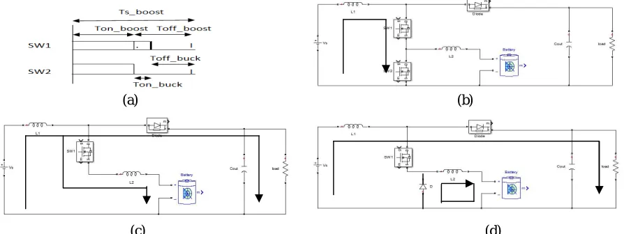
Ts_boost C. MODE 3: BOOST-BOOST MODE
(a) (b) Figure 5: Mode 3 (a) Switching Pattern, (b) Current flows during Ton_boost1.
This boost and boost mode is utilised when input alone is not sufficient to supply the power to the load then battery charge is also needed. During Ton_boost2 SW1 is OFF which makes the inductor L1 to discharge but L2 is continued to be
charged from battery since SW2 is ON. At the end of this period L2 also discharges. It is described in figure 6(a) & (b).
(a) (b)
Figure 6: Mode 3 Current flows during (a) Ton_boost 2 & Toff_boost1 and (b) Toff_boost2
Inductor L1 current increases when both the switches are ON and its ripple current is given by
ΔIL1= Vs. Ton_boost1 (13)
L1
During Ton_boost2 and Toff_boost1 , inductor L1 current decreases and its ripple current is given by
ΔIL1= (Vout – Vs) Toff_boost1 (14)
L1
Solving equations (13) and (14) gives output voltage
Vout = Vs (15)
1-Dboost1
Where Dboost1= Ton_boost1 (16)
Ts
Inductor L2 current increases when SW2 is ON and its ripple current is given by
ΔIL2= Vbattery .Ton_boost 2 (17)
L2
When SW1 and SW2 both are OFF, Inductor current decreases
ΔIL2= (Vout – Vbattery) Toff_boost 2 (18)
L2
We get output voltage From eqn (17) and (18) as
Vout = Vbattery (19)
1-Dboost2
Where Dboost2 = Ton_boost2 (20)
(a)
Figure 7: Switching Pattern for Mode 4
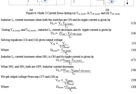
During fault condition or low input then supplying power from the source to the load is not possible. Hence battery must supply the power to the load. This operation can be done by controlling SW2. When supply voltage is less then
reverse diode of SW1 is used to discharge the energy from the battery to the load. Current flows during these actions are
shown in figure 8.
(a) (b)
Figure 8: Mode 4 current flows during (a) Ton and (b) Toff
Inductor L2 current increase during ON period and its ripple current is given by
ΔIL2= Vbattery .Ton (21)
L2
When SW2 goes off then energy in the inductor L2 and battery gets transferred to the load through reverse diode of SW1.
Current ripple is expressed as
ΔIL2= (Vout- Vbattery). Toff (22)
L2
Equations (21) and (22) are equated to get the output voltage
Vout = Vbattery (23)
1-D
Where D = Ton (24)
Ts
III.SIMULATION RESULTS
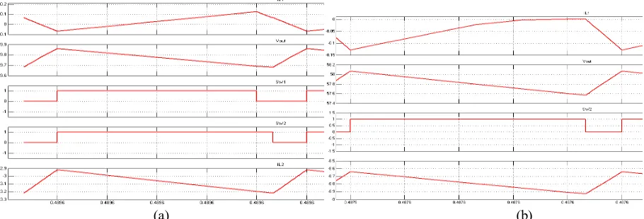
To verify the performance of all the four modes, the proposed multimode single leg converter is simulated using SIMULINK with Vin=12V, Vout=60V, L1=2.4mH, L2=1.16mH,Capacitor=100µF, Resistor=150Ω,Frequency=20KHz
and Battery= 8V,1Ah. Simulation result for mode 1 and mode 2 is shown in figure 9(a) & (b) respectively. During mode 1, when both the switches are ON then inductor L1 current rises and there is no change in the battery voltage.
During OFF period both the switches are OFF then inductor L1 current decreases. In mode 2, supply voltage is boosted
up and at the same time battery is also gets charged. During Ton_boost both the switches are ON which makes the
inductor L1 to get charged and stored charge is delivered to the load when SW2 is OFF. Battery gets charged up through
(a) (b) Figure 9: Simulation result for (a) Mode 1 (b) Mode 2
Simulation result for mode 3 and mode 4 is shown in figure 10(a) & (b) respectively. In mode 3, inductor L1 and L2 is
charged when both the switches are ON. During Ton_boost2 SW1 is OFF which makes the inductor L1 to discharge but L2
is continued to be charged from battery since SW2 is ON. At the end of this period L2 also discharges. In mode 4
battery must supply the power to the load since input is insufficient. This operation can be done by controlling SW2.
When supply voltage is less then reverse diode of SW1 is used to discharge the energy from the battery to the load.
(a) (b)
Figure 10: Simulation result for (a) Mode 3 and (b) Mode 4
IV.CONCLUSION
REFERENCES
[1] F.Blaabjerg and Z.Chen, “Power electronics as an enabling technology for renewable energy integration,” J. Power Electron. vol. 3, no. 2,pp.81-89,2003.
[2] K. Kobayashi, H. Matsuo, and Y. Sekine, “Novel solar-cell power supply system using a multiple-input DC–DC converter,” IEEE Trans. Ind.Electron., vol. 53, no. 1, pp. 281–286, Feb. 2006.
[3] R. Gopinath, K. Sangsun, H. Jae-Hong, P. N. Enjeti, M. B. Yeary, and J.W. Howze, “Development of a low cost fuel cell inverter system with DSP control,” IEEE Trans. Power Electron., vol. 19, no. 5, pp. 1256–1262,Sep. 2004.
[4] C. B. Jacobina, M. B. Rossiter Corrˆea, A. M. Nogueira Lima, and E.R. Silva, “AC motor drive systems with a reduced-switch-count converter,”IEEE Trans. Ind. Appl., vol. 39, no. 5, pp. 1333–1342, Sep. 2003.
[5] Y.-J. Lee, A. Khaligh, and A. Emadi, “Advanced integrated bidirectional AC/DC and DC/DC converter for plug-in hybrid electric vehicles,” IEEE Trans. Veh. Technol., vol. 58, no. 8, pp. 3970–3980, Oct. 2009.
[6] H. Li, F. Z. Peng, and J. S. Lawler, “A natural ZVS medium-power bidirectional DC–DC converter with minimum number of devices,” IEEE Trans. Ind. Appl., vol. 39, no. 2, pp. 525–535, Mar. 2003.
[7] W. Liu, J. Chen, T. Liang, R. Lin, and C. Liu, “Analysis, design, and control of bidirectional cascaded configuration for a fuel cell hybrid power system,” IEEE Trans. Power Electron., vol. 25, no. 6, pp. 1565–1575, Jun. 2010.