Ship Intrusion Detection Using Accelerometer and
Temperature Sensor
Jaspreet Kaur
1; Priyanka Swain
2& G.Tamizharasi
31, 2 UG Student, Dept.Of Electronics and Telecommunication Engineering, Bharath University, India
[email protected]; [email protected]3 Asst. professor, Dept. Of Electronics and Telecommunication Engineering, Bharath University, India
Abstract
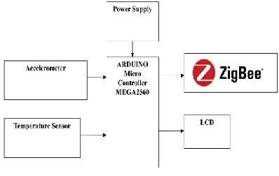
The traditional methods of detecting ships entail the use of radars or satellites which are very expensive. Besides the high cost, satellite images are easily affected by cloud cover, and it is difficult to detect small boats or ships on the sea with marine radar due to the noise or clutter generated by the uneven sea surface. Hence we go for new system. In this proposed system, the ship intrusion is going to be detected by placing accelerometer sensor and temperature sensor at the sea surface. The waves which are generated by the ocean and intruder ships are analyzed by the accelerometer and the signal is processed by the controller. The controller will transmits the data from the sea-shore section to the monitoring section in wireless communication mode called Zigbee. It’s a communication medium which operates in the frequency range of 2.4GHZ. The accelerometer sensor will distinguish both the signals and sends an individual data to the controller. The accelerometer and temperature sensors status and also the ship status are displayed in LCD.
Keywords: Zigbee; Accelerometer; Temperature Sensor.
1. Introduction
Surveillance is a critical problem for harbour protection, border control or the security of commercial facilities. The effective protection of vast near-coast sea surfaces and busy harbour areas from intrusions of unauthorized marine vessels, such as pirates, smugglers, illegal fishermen is particularly challenging. The main aim is to detect the ship, which cross over the border or secured industries using accelerometer sensor and temperature sensor.
The architecture of a ship detection prototype based on an object-oriented methodology to support the monitoring tasks is based on satellite imaging. The system’s architecture comprises a fully automatic coastline detection tool, a tool for fully or automatic ship detection in off-shore areas and a semi-automatic tool for ship detection within harbour areas. Satellite images at times do not give the correct detection because satellite images are easily affected by cloud cover. As a result, the intrusion of small sized ship or boat cannot be detected. Further they are very expensive.
This paper presents an innovative solution for ship intrusion detection. Equipped with accelerometer sensors and temperature sensor, deploy
on the sea’s surface to detect ships. This will be intimated to the microcontroller by emitting digital signal from the sensors. These digital signals will be formed as a packet and will be sent to the server node using Zigbee. The server will receive this signal using Zigbee in the receiving side and it will be displayed in visual basic software. The conducted evaluations with real data collected in our initial experiments, and provide quantitative analysis of the detection system, such as the successful detection ratio, detection latency.
2. Related Works
features are transmitted to the local head node or a sink for further signal processing and classification, due to the energy constraints of the sensor node and the limitations of the communication bandwidth. P. Latha, DR.. M. A. Bhagyaveni, Steffi Lionel [ JATIT, Feb 2014] presented three-level detection system is developed in order to find effectively the intruding ship on the sea surface with the help of a 3-axis accelerometer sensor. Compared to the existing methods, the proposed system is cost efficient and easy to deploy as it occupies less area. A functional diagram of the modules implemented in the FPGA device.Absar-ul-Hasan1, Ghalib A. Shah2 & Ather Ali [ EJSE, 2010] presented one system is implemented using the MicaZ and custom designed nodes cooperatively to monitor the human presence through a base station application. The MicaZ based sensor devices communicate with each other and traverse their data to the base station whereas the custom designed sensor nodes also communicate with the base station which has the ga-teway node for both the MicaZ and custom sensor nodes.
3. Existing System
RADAR (Radio Detection And Ranging) method is used to detect the intrusion of ship. The back ground of SAR image is quite dark and the targets are bright so it is easy to detect the object, when the wind is fierce, large waves will be stirred. The backscattering echo will be very strong. This causes many difficulties in the detection of the ships, and especially small ships. The overall accuracy is poor and it is difficult to detect the ship during bad weather condition. 3-30 MHz frequency band and are known to cover ranges up to several hundred kilometers . Low power HF radar systems have been developed especially for oceanographic applications. They use electromagnetic surface wave propagation along the salty ocean. The WERA HF radar system transmits an average power of 30 watts but it achieves detection ranges up to 200 kilometers, which are far beyond the conventional microwave radar coverage. Due to external noise, radio frequency interference, and different kinds of clutter, special techniques of target detection using the WERA system have to be applied. For a 12-hour period HF radar data were recorded and processed. The target locations detected by the HF radar using the proposed adaptive technique are passed to a tracking filter to track the ship position. It is difficult for it to detect a
small ship or boats due to the noise generated by the uneven sea surface which leads to a number of false alarms. Hence the detection ratio decreases resulting in a number of false alarms.
4. Proposed System
In this paper, Above mentioned two sensors (i.e. 3 axis accelerometer sensor and LM35 Temperature sensor) is used to detect the intrusion on the basis of distance and angle. Here one input is given as temperature sensor which is used to detect the obstacle in the sea by sensing the surround temperature increase due to ship entrance in our desired localised area. Another input accelerometer sensor is sensing transducer that provides an output proportional to acceleration vibration and shock. Here further in the next section we will discuss about working model of our proposed method.
4.1 Working model of proposed method
In the Transmitter node the real time signals such as movements, and temperature are given to the microcontroller, it converts them as digital signal. The corresponding voltage signals are transmitted through ZigBee In circuit of the Transmitter node. The inputs to the micro controller are analog signals fed by the two sensors namely temperature and accelerometer sensor. In this temperature increase is detected by temperature sensor when the ship arrives. digital. The range of the sensor used here is 1feet.The output signals of the sensors are connected to RB0 and RB1 of micro controller. The user selects the bandwidth of the accelerometer using the CX, CY, and CZ capacitors at the XOUT, YOUT, and ZOUT pins. Measurement bandwidth can be selected to suit the application from 0.5 Hz to 1600 Hz for X- and Y- axes and from 0.5 Hz to 550 Hz for the Z-axis.
4.1.1 Accelerometer
An accelerometer is a device that measures proper acceleration ("g-force"). Proper acceleration is not the same as coordinate acceleration (rate of change of velocity). For example, an accelerometer at rest on the surface of the Earth will measure an acceleration g= 9.81 m/s2 straight upwards. By contrast, accelerometers in free fall (falling toward the center of the Earth at a rate of about 9.81 m/s2) will measure zero.
Accelerometers have multiple applications in industry and science. Highly sensitive accelerometers are components of inertial navigation systems for aircraft and missiles. Accelerometers are used to detect and monitor vibration in rotating machinery. Accelerometers are used in tablet computers and digital cameras so that images on screens are always displayed upright. Accelerometers are used in drones for flight stabilisation. Pairs of accelerometers extended over a region of space can be used to detect differences (gradients) in the proper accelerations of frames of references associated with those points[clarify]. These devices are called gravity gradiometers, as they measure gradients in the gravitational field. Such pairs of accelerometers in theory may also be able to detect
gravitational waves.
Single- and multi-axis models of accelerometer are available to detect magnitude and direction of the proper acceleration (or g-force), as a vector quantity, and can be used to sense orientation (because direction of weight changes), coordinate acceleration (so long as it produces g-force or a change in g-force), vibration, shock, and falling in a resistive medium .(a case where the proper acceleration changes, since it starts at zero, then increases)
Figure 1 Block Diagram of Transmitter Node
Figure 2 Block Diagram of Receiver Node
4.1.2 Temperature Sensor
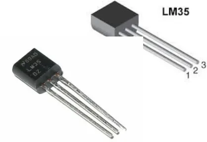
The LM35 series are precision integrated-circuit temperature devices with an output voltage linearly-proportional to the Centigrade temperature. The LM35 device has an advantage over linear temperature sensors calibrated in Kelvin, as the user is not required to subtract a large constant voltage from the output to obtain convenient Centigrade scaling.
The LM35 device does not require any external calibration or trimming to provide typical accuracies of ±¼°C at room temperature and ±¾°C over a full −55°C to 150°C temperature range. Lower cost is assured by trimming and calibration at the wafer level. The low-output impedance, linear low-output, and precise inherent calibration of the LM35 device makes interfacing to readout or control circuitry especially easy. The device is used with single power supplies, or with plus and minus supplies. As the LM35 device draws only 60 µA from the supply, it has very low self-heating of less than 0.1°C in still air. The LM35 device is rated to operate over a −55°C to 150°C temperature range, while the LM35C device is rated for a −40°C to 110°C range (−10° with improved accuracy). The LM35-series devices are available packaged in hermetic TO transistor packages, while the LM35C, LM35CA, and LM35D devices are available in the plastic TO-92 transistor package. The LM35D device is available in an 8-lead surface-mount small-outline package and a plastic TO-220 package.
4.1.3 Zigbee
ZigBee is an IEEE 802.15.4-based specification for a suite of high-level communication protocols used to create personal area networks with small, low-power digital radios. The technology defined by the ZigBee specification is intended to be simpler and less expensive than other wireless personal area networks (WPANs), such as Bluetooth or Wi-Fi. Applications include wireless light switches, electrical meters with in-home-displays, traffic management systems, and other consumer and industrial equipment that requires shortrange low-rate wireless data transfer. Its low power consumption limits transmission distances to 10– 100 meters line-of-sight, depending on power output and environmental characteristics. ZigBee devices can transmit data over long distances by passing data through a mesh network of intermediate devices to reach more distant ones. ZigBee is typically used in low data rate applications that require long battery life and secure networking (ZigBee networks are secured by 128 bit symmetric encryption keys.) ZigBee has a defined rate of 250 kbit/s, best suited for intermittent data transmissions from a sensor or input device. ZigBee was conceived in 1998, standardized in 2003, and revised in 2006. The name refers to the waggle dance of honey bees after their return to the beehive.ZigBee is a low-cost, low-power, wireless mesh network standard targeted at the wide development of long battery life devices in wireless control and monitoring applications. Zigbee devices have low latency, which further reduces average current. ZigBee chips are typically integrated with radios and with microcontrollers that have between 60-256 KB flashes memory. ZigBee operates in the industrial, scientific and medical (ISM) radio bands: 2.4 GHz in most jurisdictions worldwide; 784 MHz in China, 868 MHz in Europe and 915 MHz in the USA and Australia. Data rates vary from 20 kbit/s (868 MHz band) to 250 kbit/s (2.4 GHz band)
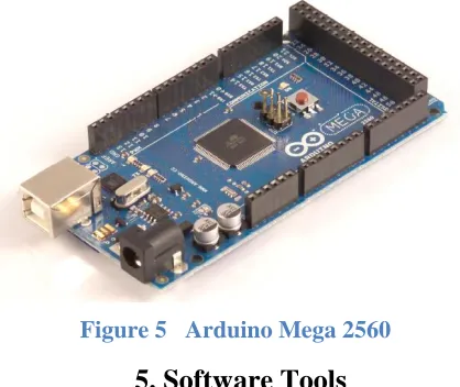
4.1.4 ARDUINO MEGA 2560
The Arduino Mega 2560 is a microcontroller board based on the ATmega2560 . It has 54 digital input/output pins (of which 14 can be used as PWM outputs), 16 analog inputs, 4 UARTs (hardware serial ports), a 16 MHz crystal oscillator, a USB connection, a power jack, an ICSP header, and a reset button. It contains everything needed to support the
microcontroller; simply connect it to a computer with a USB cable or power it with a AC-to-DC adapter or battery to get started. The Mega is compatible with most shields designed for the Arduino Duemilanove or Diecimila.
5. Software Tools
In our Project we used three software tools one for the simulation and the another one for the programming of the above mentioned Arduino Uno Microcontroller, and the third software we used for the interface making for the monitoring section.
6.1.1 Simulation Tool (Proteus ISIS)
Here we used Proteus ISIS(Intelligent Schematic Input System) as simulation tool. Proteus ISIS is the best simulation software in the world for various designs with electronics & microcontroller. It is mainly popular because of availability of almost all microcontrollers in it. So it is a handy tool to test programs and embedded designs for electronics hobbyist & expert. You can simulate your programming of microcontroller in Proteus 8 Simulation Software. After simulating your circuit using Proteus Software you can directly make PCB design with it so it could be an all in one package for students and hobbyists. So I think now you have a little bit idea about what is proteus software,
6.1.2 Programming Tool (Arduino IDE 1.6.8)
The open- source Arduino Software (IDE integrated development environment) makes it easy to
write code and upload it to the board. It runs on Windows, Mac OS X , and Linux. The environment is written in Java and based on Processing and other open – source software. This Software can be used with any Arduino Board.
5.1.3 Microsoft Visual Basic.
Visual Basic is a third-generation event-driven programming language and integrated development environment (IDE) from Microsoft for its COM programming model first released in 1991 and declared legacy in 2008. Microsoft intended Visual Basic to be relatively easy to learn and use.[1][2] Visual Basic was derived from BASIC and enables the rapid application development (RAD) of graphical user interface (GUI) applications, access to databases using Data Access Objects, Remote Data Objects, or ActiveX Data Objects, and creation of ActiveX controls and objects. A programmer can create an application using the components provided by the Visual Basic program itself. Over time the community of programmers developed third party components. Programs written in Visual Basic can also use the Windows API, which requires external function declarations.
6. Conclusion
This project gives the innovative solution for the intrusion over the border of ships and provide cost reduction. The traditional methods of detecting ships entail the use of radars or satellites which are very expensive. The input is given to the microcontroller and it is transmitted through Zigbee. The transmitted signal from the Zigbee is received by the receiver node of the Zigbee and the output is displayed as graphical representation in Visual Basic Software.
7. References
[1] A.T.Chwang & Y.Chen (2003), ‘Field Measurement of Ship Waves in Victoria Harbor’,
J.Eng.Mechanics, Vol.129, PP.1138-1148.
[2] M.Duarte&Y.Hen Hu (2004), ‘Vehicle Classification in Distributed Sensor Networks’,
[3] S.Kumar,T.Lai&A.Arora (2005), ‘Barrier Coverage with Wireless Sensors,’ PP.284-298.
[4] H.Zhu & M.Ni (2008), ‘HERO: Online Real Time Vehicle Tracking in Shanghai’, PP.942-950.
[5] E.Carapezza, J.Butman, I.Bab & A. Bucklin (2008),‘Sustainable Coastal Sensor Networks: Technologies And Challenges’, Vol.6963.
Author’s Detail
JASPREET KAUR
Pursuing bachelor of technology in Electronics & Telecommunication engineering from Bharath University, Chennai, India
Email: [email protected]
PRIYANKA SWAIN
Pursuing bachelor of technology in electronics & Telecommunication engineering from Bharath University, Chennai, India