The Converter Command for the Doubly-Fed Induction
Generator with Variable Speed used in the Wind Power
Production
Mr. V.MASTHANAIAH
Asst.Professor
PBR VITS, Kavali
Email id:
[email protected]
Miss.T.JOE NIRMAL ANUSHA
PBR VITS,Kavali
Email Id
:
[email protected]
ABSTRACT
This paper presents a global and optimal environment of the electro-mechanical conversion chain using the doubly-fed induction generator (DFIG) in wind turbines having an active power in the stator of the order of Megawatts (MW).
The establishment of the diverse models of electric parameters and the development of the methodological tools available in the environment MATLAB/Simulink are interpreted [1]. The main components of the chain of conversion are modelled and the DFIG makes the object of a particular attention as for its sizing.
Analytical and numerical methods are proposed to carry out the optimal design of the entire drive including DFIG, the multiplier mechanical speed and power converter. The implementation of the environment is illustrated by solutions
associated with different overall design requirement
specifications including the distribution of active and reactive stator powers on the DFIG [2]. The results show that there are different solutions as the original topology is presented dimensionally. The goal is to optimize the quality of energy generated by wind by manipulating the sizes of the active and reactive power as needed. The approach of the control of converters AC-DC-AC is used [3]. The method used is to adjust the stator reactive power so that the machine side converter and inverter supply side will be bidirectional, to adjust the wind speed to that of the doubly-fed induction generator, which is very favourable for energy production in wind systems. The results of the simulation will be presented in MATLAB/Simulink, as well as relatedinterpretations.
Keywords
DFIG, PWM, Rectifier, Wind Energy, Wind Turbine, Converters, Modeling, MATLAB/Simulink, Continuous bus, Converters (AC-DC-AC), Park.
1.
INTRODUCTION
Wind generation tends to play an important role in the total generation mix of the future power system due to the need to
decrease carbon dioxide (CO2) emissions resulting from
electricity production. This is due to the existence of no exploited wind resources and to the fact that it is a clean and environmental friendly energy source with a reduced cost of installation and maintenance the wind turbines based on the doubly-fed induction generators (DFIG) is an attractive solution for the wind power generation [4]. Where the rotor is fed by a variable AC voltage sources, which can be controlled in frequencies according to variable speed of the rotor shaft due to the variation of speed wind. Then the electric power at constant frequency is simply provided from the stator of the DFIG [5]. These machines are a bit more complex than the squirrel cage induction machine. In spite of the presence of rubbing contacts (rings–brushes), a main advantage of the doubly-fed induction machine is the accessibility of its both armatures from which the power flow control can be easily occurred between machine and grid. The objective of this work is the modelling, simulation and decoupled control of active and reactive powers for a DFIG [6]. The modelling will allow determining theoretical operating characteristics of the DFIG and studying the influence of the parameters on the operation of the DFIG. The main parameters are the sliding , the stator active power , and the stator reactive power .This decoupling powers control keeps the power factor very interesting[7].
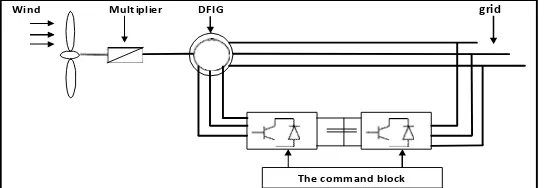
Fig 1 : DFIG in the wind energy conversion chain
The command block
Fig 2 : Synoptic diagram of the DFIG wind turbine [21]
The stator winding is connected directly to the 50 Hz grid while the rotor is fed at variable frequency through the AC/DC/AC converter. The DFIG technology allows extracting maximum energy from the wind for low wind speeds by optimizing the turbine speed, while minimizing mechanical stresses on the turbine during gusts of wind. Another advantage of the DFIG technology is the ability for power electronic converters to generate or absorb reactive power.
2.
THE CONCEPT OF THE ACTIVE
POWER
The active power of the stator is always flowing into the grid, independently of the operation state, whereas the machine operates as a motor (sub-synchronism operation) when absorbing power [8], while the machine operates as a generator (hyper-synchronism operation) when supplying power. By neglecting the power losses, the relation between the rotor power ( ) and the stator power ( ), through the slip ( ) is given by [16]:
Where is defined as the slip of the machine, which is given by:
Therefore, the net power that is generated from both stator and rotor side can be expressed as :
When the slip is negative, the machine will operate in the hyper-synchronous operation state (as a generator), while the machine will operate in the hypo-synchronous operation state (as a motor) when the slip is positive, in this case, the rotor speed is slower than the synchronous speed. By this configuration [9], the wound rotor induction generator delivers directly the of its rated power to the grid through
the stator windings, while it delivers of its rated power
through the rotor windings via the converters [16].
3.
ROTOR-SIDE CONVERTER (RSC)
CONTROL OF THEDFIG
The rotor-side converter controller is used to control independently the stator voltage alternatively (reactive power and output active power of the wind turbine [17] [18]). Since the converter operates in a stator-flux q-d reference frame, the rotor current is decomposed into an active power ( ) and a reactive power ( ) component. When the wind speed change, the active and reactive power (or voltage) of the generator will alsochange.
4.
GRID-SIDE CONVERTER (GSC)
CONTROL OF THEDFIG
Fault circuit
Operating mode Frequency control
Pitch control
Control circuit Power control
Pulse Width Modulation (PWM)
Doubly-Fed InductionGenerator
Speed controlGrid-side Vector control
Converter types
Protection circuit
Fig 3 : Simulink model of the grid-side converter
The role of the grid-side converter is to control the DC-link voltage (Voltage in the borders of the capacity which represents the continuous bus) by maintaining it constantly and it is used to generate or absorb reactive power. The DC- link voltage is used as well, with the reference frame oriented along the stator currents and stator voltages, enabling independent control of the active and reactive power flowing between the grid and the converters. The decoupling and compensation procedures of a typical grid-side converter control [10]. The difference between these two values ( and ) will go to two Proportional-Integral (PI) controllers which are used to generate the required value of stator voltage ( ). Similarly, the difference between the actual reactive power ( ) and reference value ( ) will go to
another two PI controller to generate the required value of the stator voltage ( ) [28].These
desired voltages ( and ), the outputs of both (PI) controllers, are transformed from the frame into the frame to fire the IGBTs[19].
5.
PULSE WIDTH-MODULATED
CONVERTER
The back to back converter consists of one Pulse Width Modulated (PWM) rectifier and one inverted PWM rectifier with a DC-link capacitor in between as shown in figure 4. The only difference between the inverter and rectifier is the definition of the power sign. The rotor side of the converter is modulated to give a sinusoidal line current with a chosen frequency. The DC-link voltage is regulated and kept constant by controlling the power flow through the grid side of the converter. The rectifier and inverter consists of three transistor half-bridges each built up by semiconductors [28].
Fig 4 : Back to back converter with transistor half-bridges [22]
Voltage modulation means that the momentary output voltage alters between two well defined voltage levels. A transistor half-bridge represent a switch and a PWM rectifier has three switches. The main objective of the grid-side converter is to control the DC-link voltage. The control of the grid-side converter consists of a fast inner current control loop, which controls the current through the grid-filter, and an outer slower control loop that controls the DC-link voltage. The reference frame of the inner current control loop will be
aligned with the grid flux. This means that the component
of the grid-filter current will control the active power delivered from the converter and the component of the filter current will, accordingly, control the reactive power. This implies that the outer DC-link voltage control loop has to act on the component of the grid-filter current[23].
The main task of the machine-side converter is, of course, to control the machine. This is done by having an inner fast
field-1 2
IGBT1 IGBT2 IGBT3
Three-Phase Parallel RLCLoad
oriented current control loop that controls the rotor current. The field orientation could, for example, either be aligned with the stator flux of the DFIG or the grid flux. For both reference frames the component of the rotor current largely
of the same. The expression of DC power in terms of voltages and currents [25].
determines the produced torque while the component can be used to control, for instance, the reactive power at the stator terminals [24]. The indices and indicates the direct and quadrature axis components of the reference frame and the indices and indicates rotor and stator quantities, and are the components of voltage and current on the AC side respectively, while and are the components
The current on the DC side is then given in terms of power
on the AC side and the DC-link voltage .
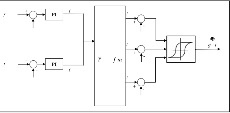
Fig 5 : Command of the DFIG [19]
The active stator power of the generator ( ) is compared with the reference point value ( ) which is determined by the wind speed. The difference between these two values will go to a Proportional Integral (PI) controller, which is used to generate the required value of rotor current ( ) [11]. Likewise, a PI controller of the reactive power side is used to generate the required rotor current ( ). The two outputs of both PI controllers are transformed from the frame into the frame to obtain the required value of rotor currents. Then, , and are algebraically summed with , and respectively [12]. The last result is obtained because of generation and demand quantities. The triggering pulses would control the IGBT switches in the rotor-side converter and that will enhance the stability of the entire system by sustaining the frequency and voltage within permissible tolerances [19] [20]. The rotor-side converter controller is used to control independently the stator voltage (or reactive power) and output active power of the wind turbine [10] [18]. The generic control loop is illustrated in Figure 5. Since the converter operates in a stator-flux q-d reference frame, the rotor current is decomposed into an active power (q-axis) and a reactive power (d-axis) component. When the wind speed change, the active and reactive (or voltage) power of the generator will also change. On the other hand the role of the grid-side converter is to control the DC- link voltage by maintaining it constant and it is also used to generate or absorb reactive power. The DC link voltage is used as well, with the q-d reference frame oriented along the stator currents and stator voltages, enabling independent control of the active and reactive power flowing between the grid and theconverters.
Table 1. Parameters of the machine
Parameters Values
Nominal power 2,5 MW
Nominal voltage 350 kV
Nominal frequency 50 Hz
Stator inductance 0.0085 H
Rotor inductance 0.0085 H
DC voltage bus(V)
DC bus voltage reference (V)
The reactive stator power(VAR)
The reactive stator power reference (VAR)
Stator according to q-axis voltage(V)
Reference voltage following the d-axis (V)
Reference voltage following the q-axis (V)
The active stator power(W)
The active stator power reference (W)
The rotor current of reference following the axis q (A)
The rotor current of reference following the axis d (A)
+
PI
- +
+ -+
PI -
-30
20
10
0
-10
-20
-30
-40
0 0.5 1 1.5 2 2.5 3
t (s)
3.5 4 4.5 5
100 0
500
0
-500
-1000
-1500
4.98 4.985 4.99
t(s) 4.99 5 5 5.005
300 0
200 0
100 0
0
-1000
-2000
-3000
0 0.5 1 1.5 2 2.5
t (s)
3 3.5 4 4.5 5
150 0
100 0 500 0 -500 -1000 -1500
The rotor reference current of the phase a (A)
The rotor reference current of the phase b (A)
The rotor reference current of the phase c (A)
The rotor current according to the phase a (A)
The rotor current according to the phase b (A)
The rotor current according to the phase c (A)
6.
RESULTS OF THESIMULATION
ANDDISCUSSIONS
The functioning of the complete device was simulated under the environment MATLAB/Simulink for one time of simulation of five seconds (5s) [13].
The strategy of the command introduced previously was tested in the case of variations of the rotor speed. In what follows, the show of the detail of the relative aspects of this strategy and the interpretation of the results of simulation. The strategy of command is based on the indirect command without locking up of power of the DFIG [14][15].
Fig 6 : Rotor current ira (A), irb (A), irc (A) according to time (s)
The rotor current is influenced by the variation of the reactive stator current absorbed by the DFIG, these currents ira (A), irb (A) andirc (A) vary approximately between (-4000A) and (+4000A), and they are independent from the profile of wind speed. The rotor currents depend on the variation of the speed of asynchronous machine with double feeding, and on the variation of the sliding of the machine according to the absorption or the supply of the rotor power.
irqi rd
Fig 7 : Rotor current irq (A), ird (A) according to time (s)
These curves show the evolution of rotor currents, these wave forms depend on the speed of the wind. These currents irq
(A) andird (A) vary between (-32A) and (+22A), and these independent from the profile of wind turbine, these values show that the systems are adapted to high power wind turbine. These currents depend on the active and reactive power.
is a is b isc
Fig 8 : Stator current isa (A), isb (A), isc (A) according to time (s)
The form of the wave of stator currents is linked to that of the stator active power and of the stator reactive power. These currents vary in sinusoidal forms. The remark is that the currents vary in a
sinusoidal manner by increasing their
amplitudes. The values of these curves vary approximately between (-1000A) and (+1000A). These curves depend on the stator flux and stator voltage.
isq isd
Fig 9 : Stator current isq (A), isd (A) according to time (s)
These currents vary approximately between (-2300A) and (+(-2300A). They depend on the speed of rotation of the machine and show the evolution of the stator active and reactive powers. These currents are independent from the profile of the wind speed.
Vsq Vsd 5000
ira irb irc
0
-5000
0 0.5 1 1.5 2 2.5 3
t (s) 3.5 4 4.5 5
ir
a
b
c
(A
)
ir
q
d
(A
)
V
sq
d
(V
)
is
q
d
(A
)
is
a
b
c(
A
0 -200 -400 -600 -800 -1000
0 0.5 1 1.5 2 2.5 3
t (s)
3.5 4 4.5 5
4
10 x 10
8 6 4 2 0 -2 -4
0 0.5 1 1.5 2 2.5 3
t (s)
3.5 4 4.5 5
1.2 1 0.8 0.6 0.4 200 150 100 50 0 -50 -100 -150 -200
4.98 4.985 4.99
t (s) 4.995 5 5.005
6 4 x10 3.5 3 2.5 2 1.5 1 0.5 0
4.98 4.985 4.99
t(s) 4.995 5 5.005
10
5
0
Fig 10 : Stator voltage Vsq (V), Vsd (V) according to time (s)
The stator voltage depends on the profile of the stator currents isq (A) and isd (A), and it depends on the stator flux (Wb) and (Wb). It should be noted that the wave forms of the tension are independent of the profile of the wind’s speed, the forms of waves of the stator tensions are independent, of the speed of wind and they are equal to the tensions of the grid. The stator voltages Vsq(V) and Vsd(V) vary between (-1800 V) and(1300V).
Generatorspeed
Fig 11 : Generator speed (rad/s) according to time (s)
The generator speed depends on the profile of wind turbine. The values vary between (-900 rad/s) and (0 rad/s), and depend on the increase in the speed of its rotation. The mechanical speed on the slow tree multiplied by the coefficient of multiplying leads to a rapid mechanical couple on the asynchronousmachine.
Cem
Fig 12 : Electromagnetic couple Cem (N.m) according to time (s)
The electromagnetic couple depend on the evolution of the stator flux (Wb), and on the rotor current irq (A). It is independent from the speed of wind, The value of this couple vary approximately between (-30000 N.m) and (+80000 N.m) in the beginning of the simulation and it becomes very adequate to the function of high power wind turbines in the end of the simulation, it fluctuates between 4.98 seconds and 4.99 seconds, and it depends from the stator inductance.
Fluxrq Fluxrd
Fig 13 : Rotor flux (Wb) according to time (s)
The rotor flux (Wb) depend on the evolution of the rotor voltage (V). They are independent from the profile of wind speed, and the values of this flux vary approximately between (-0,15Wb) and (0,95 Wb), their shape is appropriate for the stator voltages.
Vr q Vr d
Fig 14 : Rotor voltage Vrq (V), Vrd (V) according to time (s)
This curve shows the evolution of rotor voltages, these wave forms depend on the speed of the wind. They depend on the rotor currents irq (A) and ird (A). The values of these curves vary approximately between (-170V) and (+170V) in the variable ways, and it depends only from the rotor flux (Wb). The frequency of rotor tensions depends on the sliding of the machine.
Ps Ps-ref
Fig 15 : Active stator power Ps (W) according to time (s)
Fig 16 : Reactive stator power QS (VAR) according to time (s)
These curves vary between (-0.35VAR) and (0VAR), which shows the robustness of the indirect command of the DFIG used in wind energy and it depends on the rotor current (A), it’s independent from the profile of wind turbine, the simulation time is 5 seconds.
7.
CONCLUSION
The control of the DFIG has been discussed. A review of the component modelling detail required for different study objectives has been provided and appropriate component models are selected [26]. The control design is discussed and the controller performance for power strategies has been discussed and tested by MATLAB/Simulink. This method was demonstrated that it could be used for a DFIG used in wind turbine energy. The algorithm based on a traditional (PI) controller can be used under every circumstance without variations on the control hardware of the actual wind generators. The one based on an indirect opened control presents a better performance for trajectory tracking applications, with error minimisation characteristics but with the need for more computational operations. On the other hand, even if both algorithms present a correct dynamic performance in the developed tests, only the (PI) controller has really been implemented in a wind farm [27]. Thus, it would be interesting to continue analysing the real implementation of the indirect opened control. Finally, as new power regulation systems related to renewable energy sources are being applied in different countries, some research are needed on the generated active power and its quality together with economic aspects of wind farm exploitation. The test bed that has been modelled by using real time digital simulator provides a useful platform for future studies for those who have an interest in wind power and also useful for education and academic works. It can be used to implement and develop various studies such as interaction of wind farm with an energy storage system, interaction of model with a solar system, applying protection system technology and developing new advanced control schemes[28].
8.
REFERENCES
[1] A. Alesina, M. Venturini, «Intrinsic Amplitude Limits and Optimum Design of 9 Switches Direct PWM AC - AC Converter». Proc. of PESC con. pp. 1284-1290, Rec. April1988.
[2] Mister. Budinger, D. Leray, and Y. Deblezer, "Wind turbines and variable speed", The magazine 3EI, flight. 21, pp. (79-84, 2000).
[3] S. HEIER, Grid Integration of Wind Energy, Conversion Systems. New York: John Wiley & Sons Ltd (1998).
[4] H. Akagi and H. Sato, "Control and performance of a doubly-fed induction machine Intended for a flywheel
energy storage system", IEEE Trans. Power Electron., vol. 17, No. 1, pp. 109–116, Jan. 2002.
[5] H. Akagi, Y. Kanazawa, and A. Nabae, "Instantaneous reactive power compensators comprising switching devices without energy storage components", IEEE Trans. Ind. Applicat. vol. 20, no. 3, pp. 625–630,
May/June 1984.
[6] J. Bendl, M. Chombt, and L. Schreier, "Adjustable-speed operation of doubly Fed-Machines in pumped storage power plants", in Proc. Ninth International Conference on Electrical Machines and Drives, Sep., 1–3, 1999, pp. 223– 227.
[7] S. Bolik, "Grid requirements challenges for wind turbines", in Proc. Int. Work. Large-Scale Integration Wind Power Transmission Networks Offshore Wind Farms, Billund, Denmark, Oct., 20–21,2003.
[8] M. H. Bollen, Understanding Power Quality Problems
:Voltags Sags and Interruptions. Piscataway, NJ, USA
:IEEE Press, 2002.
[9] M. Bongiorno, "Control of voltage source converters for voltage dip mitigation in Shunt and series configuration", Chalmers University of Technology, Goteborg, Sweden, Licentiate Thesis 515L, Nov. 2004.
[10] O. Carlson, J. Hylander, and K. Thorborg, "Survey of variable speed operation of wind Turbines", in Proc. of European Union Wind Energy Conference, Goteborg, Sweden, May, 20–24, 1996, pp. 406–409.
[11] L. Congwei, W. Haiqing, S. Xudong, and L. Fahai, "Research of stability of double fed Induction motor vector control system", in Proc. of the Fifth International Conference On Electrical Machines and Systems, vol. 2, Shenyang, China, Aug. 18–20, 2001, pp. 203–1206.
[12] R. Datta and V. T. Ranganathan, "A simple position- sensorless algorithm for rotor-side field-oriented control of wound-rotor induction machine", IEEE Trans. Ind. Electron. vol. 48, no. 4, pp. 786–793, Aug. 2001.
[13] F. B. del Blanco, M. W. Degner, and R. D. Lorenz, "Dynamic analysis of current Regulators for ac motors using complex vectors", IEEE Trans. Ind. Applicat., vol. 35, No. 6, pp. 1424–1432, Nov. /Dec. 1999.
[14] A. Dittrich and A. Stoev, "Grid voltage fault proof doubly-fed induction generator System", in Proc. Power Electronics and Applications (EPE), Toulouse, France, Sep. 2003.
[15] J. B. Ekanayake, L. Holdsworth, and N. Jenkins, "Comparison of 5th order and 3rd order Machine models for doubly fed induction generator (DFIG) wind turbines", Electric Power Systems Research, vol. 67, pp. 207–215, Dec. 2003.
[16] ABB Technical application papers no. 13, "Wind power plants", ABB document 1SDC007112G0201 - 10/2011 - 4.000.
[17] C. Hamon, "Doubly-fed Induction Generator Modelling and Control in Dig Silent Power Factory", Master Thesis, KTH School of Electrical Engineering, 2010.
Tennessee Technological University, December 2011.
[19] M. Singh and S. Santoso, "Dynamic models for wind turbines and wind power plants", NREL, Tech. Rep., Oct 2011.
[20] J. Prabhakar and K. Ragavan, "Power Management Based Current Control Technique for Photovoltaic- Battery Assisted Wind-Hydro Hybrid System", International Journal of Emerging Electric Power Systems,2013.
[21] SemanSlavomir, Antero Arkkio, Julius Saitz, JoukoNiiranen, "Performance Study of a Doubly Fed Wind- Power Induction Generator Under Network
Disturbances", IEEE Transactions on energy conversion, vol. 21, no. 4, December 2006.
[22] Carlsson, A. (1998). The back to back converter :control
and design. Lund. Department of Industrial Electrical Engineering and Automation. Lund Institute of Technology.
[23] P. C. Krause :"Analysis of Electric machinery" McGraw-Hill Inc, New York, 1994.
[24] Slotine, J.J.E., and Li, W. :"Applied nonlinear control", Prentice Hall, Englewood Cliffs, New Jersey, 1991.
[25] J. Niiranen, "Voltage dip ride through of a doubly-fed generator equipped with an active crowbar", Proceedings of Nordic Wind Power Conference; March 2004.
[26] Abdelhadi EL MOUDDEN, Abdelali AARIB,
AbdelhamidHMIDAT :"Optimization of the robust
control of the doubly-fed induction generator used in the centralized production of wind energy", The National School of Electricity and Mechanics (ENSEM), Casablanca, Morocco, July 2014.
[27] Abdelhadi EL MOUDDEN, Abdelali AARIB, Aïcha
WAHABI, Fatima EzzahraBOUNIFLI :"Command of
the active and reactive stator powers of the doubly-fed induction generator used in wind energy", The National School of Electricity and Mechanics (ENSEM), Casablanca, Morocco ,October 2014..
[28] Mohammad RashedM.Altimania: "Modeling of doubly- fed induction generators connected to distribution system based on eMEGASim® real-time digital simulator", A Thesis Submitted to the Faculty of the University of Tennessee at Chattanooga in Partial Fulfillment of the Requirements of the Degree of Master of Engineering, May 2014.
9.
AUTHOR’SPROFILE
Student Details
Miss.T.JOE NIRMAL ANUSHA was born in India.
She pursuing M.Tech degree in Power Electronics in
EEE Department in PBR Visvodaya institute of
Technology and Science, Kavali, S.P.S.R Nellore
District, Andhra Pradesh State, India.
mail id:
[email protected]
Guide Details
![Fig 2 : Synoptic diagram of the DFIG wind turbine [21]](https://thumb-us.123doks.com/thumbv2/123dok_us/7784599.1287321/2.612.92.520.88.341/fig-synoptic-diagram-dfig-wind-turbine.webp)