Modelling and Speed Control Analysis of
Asynchronous Motor using SVPWM
Shubham Srivastava¹, A.K. Bhardwaj²
M.Tech Scholar, Dept. of Electrical Engineering, SHIATS, Allahabad, U.P, India ¹
Associate Professor & Head, Dept. of Electrical Engineering, SHIATS, Allahabad, U.P, India²
ABSTRACT
:
This paper aims on space vector modulation (SVM) for controlling of induction motor. It is not easy tocontrol an induction motor (IM) in light of its poor dynamic response in correlation to the DC motor. SVPWM increase voltage utilization factor up to 0.906 by adding the zero sequence voltage. Space vector PWM (SVPWM) is widely used because of their better dc bus utilization and easier digital realization. It is achievable to control the electromagnetic torque and stator flux linkage using optimized selection of inverter switching vectors using VSI. SVPWM inverters are recently showing growing popularity for multi-megawatt industrial drive applications. In this paper V-F control used because of its simplicity and good response here simulation of open loop control of induction motor using V-F principle by space vector modulation is done using MATLAB/Simulink.
KEYWORDS: Two-level inverter; Space vector pulse width modulation (SVPWM); V-F control;
MOSFET;Asynchronous motor etc.
I. INTRODUCTION
Most industrial process required some kind of control or adjustment for normal operation. Due to recent development in power electronic device it is easy to control high power and manage voltage, current and frequency as per requirement in process. In electrical variable speed drive (VSD) power converter control the flow of power to load supplied from source to control speed or torque. Many PWM strategies developed over the years but SVPWM is considering as the best because of operate at constant switching frequency and gives better DC bus utilization. The control techniques for induction motor divided into two parts: scalar control and vector control. In this paper constant V/f scalar control is used because of simple to understand and implement. In this paper design of VSI using space vector modulation is presented for controlling of induction motor. A simple constant V/f technique by open and closed loop used for control the machine speed. Analysis is done using MATLAB.
Space vector PWM refers to a special switching scheme of the six power semiconductor switches of athree phase power converter. Space vector PWM (SVPWM) has become a popular PWM technique for threephase voltagesource inverters inapplications such as control of induction and permanent magnet synchronous motors. The mentioned drawbacks of the sinusoidal PWM and hysteresisband current control are reduced using this technique. Instead of using a separate modulator for each of the three phases (as in the previous techniques), the complexreference voltage vector s processed as a whole. Therefore, the interaction between the three motor phases is considered. It has been shown, that SVPWM generates less harmonic distortion in both output voltage and current applied to the phases of an ac motor and provides a more efficient use of the supply voltage in comparison with sinusoidal modulation techniques.SVPWM provides a constant switching frequency and therefore the switching frequency can be adjusted easily. Although SVPWM is more complicated than sinusoidal PWM and hysteresis band current control, it may be implemented easily with modern DSPbased control systems.
Nr = Ns (1-s)(2)
Rotor speed, Nr = ( 1- S ). (3)
Thus, speed of an induction motor can be varied by changing frequency (f), slip (S), or number of poles (P) for which the winding are wound. The scalar control is based on changing any one parameter like frequency, slip or pole. The speed can be changed by increasing or decreasing in frequency but this result in change of impedance. This in turn is the reason for change in current drawn by the motor. Reduction in supply frequency increase the air gap flux which result in saturation of the core. To avoid these problems, it is necessary to vary the frequency and the voltage at the same time. According to induced voltage equation (4) constant V/HZ control gives constant flux in the stator.
=
4.44 N∅ (4)The torque-speed equation (5) of induction motors reveals the voltage-torque-frequency relation, given by,
Torque developed by induction motor remains constant if V/f ratio is constant up to the base speed. Beyond base speed torque is decrease in inverse proportion to increase in frequency because voltage can’t be higher than rated value of equipment.
Fig. 1-Frequency-voltage-torque curve
Other than the variation in speed, the torque-speed characteristics of the V/F control reveal the following: The starting current is low.
The stable operating region of the motor is increased. Instead of simply running at its base/ rated speed (NB), the motor can be run typically from 5% of the synchronous speed (NS) up to the base speed. The torque generated by the motor can be kept constant throughout this region.
B. OPEN LOOP SPEED CONTROL
In open loop control there is feedback so response is slow, so it applicable where accuracy is not primary disquiet. As per shown in fig 2 frequencies is define from required speed and rough assumption is made that motor follow its synchronous speed. Required voltage is determined from V/f curve given by motor manufacturer
.
Due to simplicity, low cost and immune from feedback system, open loop V/f control system is widely used in industry where precision is not great concern.
Fig. 2-diagram of open loop V/f control
C. SPACE VECTOR MODULATION
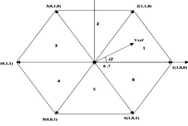
Variable voltage and frequency is obtained from VSI. Many PWM techniques developed over years but ideal modulation scheme looks for lower harmonics generation, linear modulation range and low switching losses. SVPWM fulfil all requirements and also operate at a constant switching frequency so it considers as best PWM techniques. SVPWM treats inverter as whole while traditional PWM techniques consider as N single phase inverter tied together. Three phase inverter have eight possible combinations; two of them are a null value because all terminals are connected to same potential either at ground or at Vcc. The remaining six combinations give non-zero voltage and all are represented as a state which form hexagon in plane spanning 60 degree each.
Fig. 3-Phase voltage representation
As shown in fig 4 each state is represented by three numbered coordinate system which is corresponding to the state of the inverter leg. 0 represent conduction of lower switch and 1 represent conduction of upper switch. There is a command vector which is rotate at same angular speed of desired frequency and position of vector gives instantaneous voltage output of the inverter. When vector lies between two state vectors, a vector sum is made in order to obtain desired voltage, given by
V= Va +Vb +Vo (7)
corresponding to the state of the inverter leg. 0 represent conduction of lower switch and 1 represent conduction of upper switch. There is a command vector which is rotate at same angular speed of desired frequency and position of vector gives instantaneous voltage output of the inverter.
According to the modulation index, PWM range is divided into linear and over-modulation range. MI = V/ (8)
II. MATLAB/SIMULINK MODEL
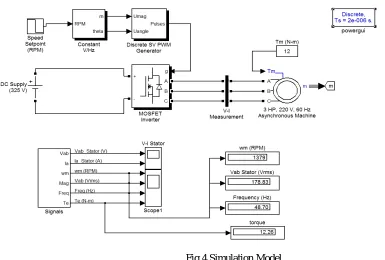
A 3-phase squirrel-cage motor rated 3 HP, 220 V, 60 Hz, 1725 rpm is fed by a 3-phase MOSFET inverter connected to a DC voltage source of 325 V. The inverter is modelled using the "Universal Bridge" block and the motor by the "Asynchronous Machine" block. Its stator leakage inductance L is set to twice its actual value to simulate the effect of a smoothing reactor placed between the inverter and the machine. The load torque applied to the machine's shaft is constant and set to its nominal value of 12 N.m.The firing pulses to the inverter are generated by the "Space-Vector PWM modulator" block of the SPS library. The chopping frequency is set to 1980 Hz and the input reference vector to "Magnitude-Angle"Speed control of the motor is performed by the "Constant V/Hz" block. The magnitude and frequency of the stator voltages are set based on the speed setpoint. By varying the stator voltages magnitude in proportion with frequency, the stator flux is kept constant.
Fig 4 Simulation Model
III. SIMULATION RESULTS
Fig 5 Speed-time Output characteristic of 3-phase I.M.
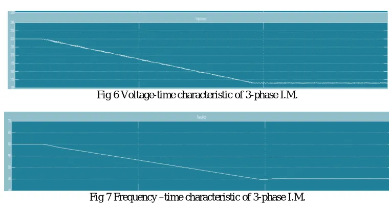
Fig.6 & Fig.7 shows the change in applied voltage and corresponding change in frequency with respect to time.
Fig 6 Voltage-time characteristic of 3-phase I.M.
Fig 7 Frequency –time characteristic of 3-phase I.M.
Fig.8 shows attain constant torque after having small variation with respect to time.
Fig 8 Output Torque-time characteristic of 3-phase I.M.
Fig 9 shows that the wave form of stator voltage of asynchronous motor used in this model.
Fig.10 shows the sinusoidal waveform of stator current of asynchronous motor used in the model.
Fig 10 Ia stator current characteristic of I.M.
IV. RESULTS
Table 1
When induction motor parameter are set according to the following table i.e. preset speed condition, desired steady torque and specified input voltage and frequency. The controlled steady state speed is obtained shown in fig.5
Simultaneously the output torque is obtained which is equivalent to the desired torque. This steady state torque characteristic shown in fig.8 and tabulated below:
Desired motor torque
(Tm)
Range of Preset Speed
Initial frequency (60hz) Initial Voltage (220V)
Controlled steady state
speed (Ws)
Output Torque (Te)
Initial speed Final
speed
Final frequency
Final Voltage
11.9 1725 1300 45.2 165.8 1275 11.84
11.9 1825 1400 48.7 178.8 1379 12.16
12 1825 1400 48.7 178.8 1379 12.26
12 1950 1525 53.04 194.4 1509 12.34
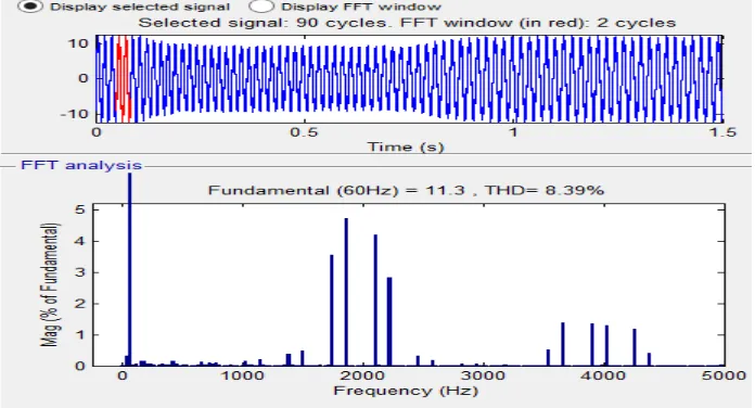
We havesimulated and analyze open loop system and obtain the THD of phase current and voltage in fig11 & fig.12 through FFT analysis of powergui block.
Fig12 FFT of Vab stator (THD 56.61%)
V. CONCLUSION
After measurement and results obtained measuring the electrical characteristics of induction machine we have come to the following conclusions:
According to the simulation result the THD obtained in the output waveform of voltage is 56.51% and current is 8.39%. SVPWM gives smooth transition between linear and over modulation region. SVPWM gives effective control of asynchronous motor. V/f control gives effective control of induction motor for higher speed, at low speed low speed response become low. Controlling of motor is done effectively using space vector PWM in both mode without exceeding current and torque limit. SVPWM increases performances as well as drives life time.The stator flux is also kept constant. The motor torque decreases only for the duration when voltage decreases and attains the same value when voltage maintains constant value. This drive system can be used energy saving in variable torque load applications like boiler feed pumps conveyors, rolling mills, printing machines etc.
REFERENCES
[1] Kwasinski, A., Krein, P. T., and Chapman, P. L., “Time domain comparison of pulse-width modulation schemes,” IEEE Trans. Power Electron., Vol. 1, No. 3, pp. 64–68, September 2003.
[2] Narayanan, G., Ranganathan, V. T, Zhao, D., and Krishnamurthy, Harish K., “Space vector based hybrid PWM techniques for reduced current ripple,” IEEE Trans. Ind. Electron., Vol. 55, No. 4, pp. 1614–1627, April 2008.
[3] Patil, U. V., Suryawanshi, H. M., and Renge, M. M., “Torque ripple minimization in direct torque control induction motor drive using space vector controlled diode clamped multi-level inverter,” Elect. Power Compon. Syst., Vol. 40, pp. 1060–1076, August 2011.
[4] Takahashi, I., and Noguchi, T., “A new quick-response and highefficiency control strategy of an induction motor,” IEEE Trans. Ind. Appl., Vol. 22, No. 5, pp. 820–827, September 1986..
[5] BusquetsMonge, S., Bordonau,J,Boroyevi -ch,D., et al. The nearest three virtual space vector PWM - a modulation for the comprehensive neutral -point balancing in the three-level NPC inverter [J]. IEEE Power Electronics Society. 2004,2 (1): 11-15..