ISSN (Print) : 2320 – 3765 ISSN (Online): 2278 – 8875
I
nternational
J
ournal of
A
dvanced
R
esearch in
E
lectrical,
E
lectronics and
I
nstrumentation
E
ngineering
(An ISO 3297: 2007 Certified Organization)
Vol. 5, Issue 1, January 2016
Fuzzy Logic Controller of STATCOM for
Voltage Regulation
Krutika Ashokrao Bhosale, Asst. Prof. Rayarao Santhosh Kumar
Matsyodari Shikshan Sansthas College of Engineering and Technology, Jalna Dr. Babasaheb Ambedkar Marathwada
University, Aurangabad, India
Matsyodari Shikshan Sansthas College of Engineering and Technology, Jalna Dr. BabasahebAmbedkar Marathwada
University, Aurangabad, India
ABSTRACT: Structure of control framework for AC-voltage controller STATCOM with fluffy rationale controller is like a nonlinear PI controller. In this, we have utilized a fluffy rationale controller rather than ordinary PI controller.Standard managementler for STATCOM furthermore a couple of usages of PI controller get PI grabs by method for an experimentation approach gives control parameters to the best execution at a given operators reason won't not be fruitful at a specific specialists reason. This endeavor proposes a new out of the crate new organization model maintained adaptable PI organization, which might self-switch the organization gets all through an unsettling impact. The parameters are changed in a manner that mistake sign is minimized. To get the fancied result, we should apply a standard based framework. The standard base for FLC is composed by the experience of contemplating the execution of STATCOM. The expected structure is maintained in MATLAB/SIMULINK PC code environment.
KEYWORDS- Adaptive management, Fuzzy Logic Controller, proportional-integral (PI) management, reactive powercompensation, STATCOM, voltage stability.
I. INTRODUCTION
Adaptable AC Transmission Systems (FACTS) utilizes power hardware gadget to control the genuine and receptive force in current force framework for the better use of the current system. They are utilized to soggy out force swings in this way lessening the transmission misfortune by legitimate receptive influence control and upgrade the transient dependability. Quick acting Static synchronous compensator (STATCOM) is broadly utilized as dynamic shunt compensator for receptive force control in the transmission system. VSC based STATCOM have been produced to control power framework motion amid issue condition. It has been accounted for by numerous scrutinizes that STATCOM with cutting edge controller can be utilized to create steadiness of arrangement of multi machine framework and a solitary machine endless transport framework. Numerous propelled control advancements have been proposed by the analysts for STATCOM in enhancing security of force framework steadiness.
ISSN (Print) : 2320 – 3765 ISSN (Online): 2278 – 8875
I
nternational
J
ournal of
A
dvanced
R
esearch in
E
lectrical,
E
lectronics and
I
nstrumentation
E
ngineering
(An ISO 3297: 2007 Certified Organization)
Vol. 5, Issue 1, January 2016
controls are planned. This management depends on the designer’s expertise to get best parameters. In [18] an exceedingly new STATCOM state feedback style is introduced supported a zero set idea. Almost like [15]-[17] the ultimate gains of the STATCOM state feedback controller still rely upon the designer’s alternative. In [19]-[21] an exceedingly fuzzy PImanagement methodology is planned to tune PI controller gains.However, it is still up to the designer to settle on the particular, settled gains. In [22] the population-based search technique is applied to tune controller gains. However, this methodology typically desires a protracted period of time to calculate the controller gains. A trade off of performance and also the sort of operation conditions still needs to be created throughout the designer’s decision-making method. Thus, extremely economical results might not be forever accomplishable underneath a selected in operation condition. Completely different from these previous works, the motivation of this paper is to propose an impact methodology that may guarantee a fast and consistent desired response once the system operation condition varies in alternative words, the modification of the external condition won't have a negative impact, like slower response, overshoot, or perhaps instability to the performance. There are three inputs of FLC and one output. This input and output gains of FLC are tuned by trial method in such a way to satisfy the minimum error, and best output response is tuned by changing the gain and other parameters. The parameters are changed in such a way that error signal is minimized. To get the desired result, we must apply a rule-based system. The rule base for FLC is designed by the experience of studying the performance of STATCOM.
Fig1. Dynamic model system with STATCOM
Fig2. V-I Characteristics of STATCOM
II. STATCOM MODEL AND CONTROL
A. STATCOM model with fuzzy logic controller (flc).Structure of control system for AC-voltage regulator STATCOM with fuzzy logic controller. The fuzzy main controller is similar to a nonlinear PI controller. Nine fuzzy sets or linguistic variables are defined for E, ∆E1 & ∆E2, and nine for output signal. Fuzzy logic controller is a better option
ISSN (Print) : 2320 – 3765 ISSN (Online): 2278 – 8875
I
nternational
J
ournal of
A
dvanced
R
esearch in
E
lectrical,
E
lectronics and
I
nstrumentation
E
ngineering
(An ISO 3297: 2007 Certified Organization)
Vol. 5, Issue 1, January 2016
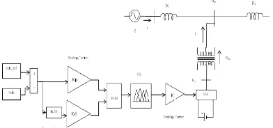
are three inputs of FLC and one output. This input and output gains of FLC are tuned by trial method in such a way to satisfy the minimum error, and best output response is tuned by changing the gain and other parameters. The parameters are changed in such a way that error signal is minimized. To get the desired result, we must apply a rule-based system. The rule base for FLC is designed by the experience of studying the performance of STATCOM.
Fig. 3 Block diagram of STATCOM model with fuzzy logic controller (FLC)
III. ADAPTIVE PI CONTROL OF STATCOM
A.Idea of the planned adjective PI management technique the STATCOM with mounted PI management parameters might not reach the specified and acceptable response within the facility once the ability system operative condition (e.g., hundreds or transmissions) changes. Associateadjustive PI management technique is conferred.
Fig. 4Adaptive PI control block for STATCOM
Here specified response and to avoid activity trial-and-error studies to search out appropriate parameters for PI controllers once a replacement STATCOM is put in in an exceedingly facility. With this adjective PI management technique, the propellant self-adjustment of PI management parameters is complete. Associate adjective PI management block for STATCOM is shown in Fig. 3. In Fig. 3, the measured voltage and therefore the reference voltage, and the q-axis reference current and therefore the q-axis current square measure in per– unit values. The proportional and integral components of the transformer gains square measure denoted by kp−vand ki−v, severally.
Similarly, the gains and represent the proportional and integral components, severally, of the present regulator. During this system, the allowable voltage errorkd is set to zero. The kp−v,ki−v,kp−I and ki−I can be set to associate capricious initial
ISSN (Print) : 2320 – 3765 ISSN (Online): 2278 – 8875
I
nternational
J
ournal of
A
dvanced
R
esearch in
E
lectrical,
E
lectronics and
I
nstrumentation
E
ngineering
(An ISO 3297: 2007 Certified Organization)
Vol. 5, Issue 1, January 2016
1)The bus voltage vm(t)is measured in real time.
2)Once the measured bus voltage over time, the target steady-state voltage, that is ready to 1.0 per unit (p.u.) within the discussion and examples, vm(t)is compared with vnn. supported the specified reference voltage curve, kp−I and ki−I are
dynamically adjusted so as to create the measured voltage match the specified reference voltage, and therefore the q-axis reference current is obtained.
3) Within the inner loop, Iqref is compared with the q-axis current Iq. Exploitation the similar management technique just
like the one for the outer loop, the parameters kp−I and ki−I is adjusted supported the error. Then, an appropriate angle is
found and eventually the dc voltage in STATCOM is changed specified STATCOMprovides the precise quantity of reactive power injected into the system to stay the bus voltage at the specified price.
It ought to be noted that the present and Imaxand Iminthe angle αmaxand αminsquare measure the bounds obligatory with
the thought of the most reactive power generation capability of the STATCOM controlled during this manner. Ifone in every of the most or minimum limits is reached, the most capability of the STATCOM to inject reactive power has been reached. Certainly, as long because the STATCOM size has been befittingly studied throughout designing stages for inserting the STATCOM into the ability system, the STATCOM mustn't reach its limit unexpectedly
Fig. 5Reference voltage curve.
Since the inner loop management is analogous to the outer loop management, the mathematical technique to mechanically regulate PI controller gains within the outer loop is mentioned during this section for illustrative functions. the same analysis is applied to the inner loop.
IV. FLOWCHART OF OPERATING PROCEDURE FOR FUZZY LOGIC CONTROLLER IN STATCOM
ISSN (Print) : 2320 – 3765 ISSN (Online): 2278 – 8875
I
nternational
J
ournal of
A
dvanced
R
esearch in
E
lectrical,
E
lectronics and
I
nstrumentation
E
ngineering
(An ISO 3297: 2007 Certified Organization)
Vol. 5, Issue 1, January 2016
Fig 6Flowchart Of Operating Procedure For Fuzzy Logic Controller (FLC) In STATCOM
V. ALL VALUES OF ALL THE PARAMETERS
Original Control
Lowest Voltage after disturbance 0.9938 p.u. Time (sec) when V= 1.0 0.4095 Sec
toreachV = 1.0 0.2095 Sec
Var Amount at Steady State 97.76 MVar Time to reach Steady State Var 0.4095 Sec
Performance comparison for the original system parameters
For STATCOM:
Rated Power = 100 MVAr Rated voltage= 138 kV
ISSN (Print) : 2320 – 3765 ISSN (Online): 2278 – 8875
I
nternational
J
ournal of
A
dvanced
R
esearch in
E
lectrical,
E
lectronics and
I
nstrumentation
E
ngineering
(An ISO 3297: 2007 Certified Organization)
Vol. 5, Issue 1, January 2016
P= 100 MW Q= 80 MVAr
VI. FLOWCHARTS OF THE ADAPTIVE PI CONTROL PROCEDURE
1. The accommodative PI management method begins at begin. The bus voltage over time ( ) is sampled in line with a desired rate. Then ( ) is compared with .If ( ) = , then there is no reason to alter any of the known parameters Kp_V(t),Ki_V(t),Kp_I(t)and Ki_I(t).The power system is running swimmingly. On the opposite hand, if ( ) ≠ , then
accommodative PI management begins.
2.The measured voltage is compared with , the reference voltage outlined in (10). Then, Kp_V(t)and area unit adjusted
within the transformer block (outer loop) supported (23) and (24), that results in associate updated Iqref viaa current
electrical circuit as showninFig.3
3.Then, the Iqrefis compared with the measured q-currentIqThe management gains Kp_I(t)and Ki_I(t)area unit adjusted
supported (25) and (26). Then, the phase α is decided and felt a electrical circuit for output, that basically decides the
reactive power output from the STATCOM.
4.Next, if |ΔV(t)|is not at intervals a tolerance threshold VЄ, which may be a terribly tiny price like 0.0001 p.u., the
transformer block and current regulator blocks area unit re-entered till the amendment is a smaller amount than the given threshold VЄ.
VII. SIMULATION RESULT WAVEFORM OF FUZZY LOGIC CONTROLLER (FLC)
Fig. 7. Studied system
ISSN (Print) : 2320 – 3765 ISSN (Online): 2278 – 8875
I
nternational
J
ournal of
A
dvanced
R
esearch in
E
lectrical,
E
lectronics and
I
nstrumentation
E
ngineering
(An ISO 3297: 2007 Certified Organization)
Vol. 5, Issue 1, January 2016
A. Change of PI Control Gains
The other system parameters remain unchanged while the PI controller gains for the original control are changed tok ,k ,k and k = 1. The dynamic control gains, which are independent of the initial values before the
disturbance but depend on the post fault conditions.
Based on the Fuzzy control model can be designed, and the results are shown in Figs. respectively.
Fig.8 Results of α with changed PI control gains
(a)
(b)
ISSN (Print) : 2320 – 3765 ISSN (Online): 2278 – 8875
I
nternational
J
ournal of
A
dvanced
R
esearch in
E
lectrical,
E
lectronics and
I
nstrumentation
E
ngineering
(An ISO 3297: 2007 Certified Organization)
Vol. 5, Issue 1, January 2016
B. Change of Transmission Network
The PI controller gains remain unchanged, as in the original model. However, line 1 is switched off at 0.2 s to represent a different network which may correspond to scheduled transmission maintenance. The adaptive PI control model can be designed to automatically react to changes in the transmission network. The results are shown in Figs the initial transients immediately after 0.2 s lead to an over absorption by the STATCOM, while the adaptive PI control gives a much smoother and quicker response, as shown in Fig.
Fig.10 Results of α with change of transmission network
(a)
(b)
ISSN (Print) : 2320 – 3765 ISSN (Online): 2278 – 8875
I
nternational
J
ournal of
A
dvanced
R
esearch in
E
lectrical,
E
lectronics and
I
nstrumentation
E
ngineering
(An ISO 3297: 2007 Certified Organization)
Vol. 5, Issue 1, January 2016
C.Two Consecutive Disturbances
In this case, a disturbance at 0.2 s causes a voltage decrease from 1.0 to 0.989 p.u. and it occurs at substation A. After that, line 1 is switched off at 0.25 s. The results are shown in.it is apparent that the adaptive PI control can achieve much quicker response than the original one, which makes the system voltage drop much less than the original control during the second disturbance.
That the largest voltage drop during the second disturbance event (starting at 0.25 s) with the original control is 0.012 p.u., while it is 0.006 p.u. with the proposed adaptive control.
Fig.12 Results of α with two consecutive disturbances
ISSN (Print) : 2320 – 3765 ISSN (Online): 2278 – 8875
I
nternational
J
ournal of
A
dvanced
R
esearch in
E
lectrical,
E
lectronics and
I
nstrumentation
E
ngineering
(An ISO 3297: 2007 Certified Organization)
Vol. 5, Issue 1, January 2016
VIII. CONCLUSION AND FUTURE SCOPE
The principle target of the proposed framework is to build up a circuit for improving transient steadiness at 33KV network. Fluffy rationale controller was utilized as a part of controlling STATCOM. It was found that numerical demonstrating in synchronous turning outline diminishes the circuit multifaceted nature. In the writing, different STATCOM control strategies have been talked about including numerous uses of PI controllers. In any case, these past works get the PI picks up by means of a trialand-blunder approach or broad studies with a tradeoff of execution and materialness. Thus, control parameters for the ideal execution at a given working point may not generally be successful at an alternate working point. Subsequent to the conformity is self-governing; this gives the "fitting and-play" ability for STATCOM operation. In the reproduction examine, the proposed versatile fluffy rationale control for STATCOM is contrasted and the routine STATCOM control with pretuned altered PI increases to check the benefits of the proposed technique. The outcomes demonstrate that the versatile PI control gives reliably brilliant execution under different working conditions, for example, distinctive introductory control increases, diverse burden levels, and change of the transmission system, successive unsettling influences, and an extreme aggravation.
IX. FUTURE WORK
In contrast, the conventional STATCOM control with fixed fuzzy logic controller gains has acceptable performance in the original system, but may not perform as efficient as the proposed control method when there is a change of system conditions. Future work may lie in the investigation of multiple STATCOMs since the interaction among different STATCOMs may affect each other. Also, the extension to other power system control problems can be explored.
REFERENCES
1. F. Li, J. D. Kueck, D. T. Rizy, and T. King, “A preliminary analysis of the economics of using distributed energy as a source of reactive power supply,” Oak Ridge, TN, USA, First Quart. Rep. Fiscal Year, Apr. 2006, Oak Ridge Nat. Lab.
2. A. Jain, K. Joshi, A. Behal, and N. Mohan, “Voltage regulation with STATCOMs: Modeling, control and results,”IEEE Trans. Power Del., vol. 21, no. 2, pp. 726–735, Apr. 2006.
3. D. Soto and R. Pena, “Nonlinear control strategies for cascaded multilevel STATCOMs,”IEEE Trans. Power Del., vol. 19, no. 4, pp. 1919– 1927, Oct. 2004.
4. F.Liu,S.Mei,Q.Lu,Y.Ni,F.F.Wu,andA.Yokoyama,“Thenonlinear internal control of STATCOM: Theory and application,” Int. J. Elect. Power Energy Syst., vol. 25, no. 6, pp. 421–430, 2003.
5. C. Hochgraf and R. H. Lasseter, “STATCOM controls for operation with unbalanced voltage,”IEEETrans. Power Del.,vol.13,no.2,pp. 538–544, Apr. 1998.
6. G. E. Valdarannma, P. Mattavalli, and A. M. Stankonic, “Reactive power and unbalance compensation using STATCOM with dissipativity based control,” IEEE Trans. Control Syst. Technol., vol. 19, no. 5, pp. 598–608, Sep. 2001.
7. H. F. Wang, “Phillips-Heffron model of power systems installed with STATCOM and applications,”Proc. Inst. Elect. Eng., Gen. Transm. Distrib., vol. 146, no. 5, pp. 521–527, Sep. 1999.
8. H. F. Wang, “Applications of damping torque analysis to statcom control,”Int. J. Elect. Power Energy Syst., vol. 22, pp. 197–204, 2000. 9. Y.Han,Y.O.Lee,andC.C.Chung,“Modified non-linear damping of internal dynamics via feedback linearisation for static synchronous
compensator,”IET Gen. Transm. Distrib., vol. 5, no. 9, pp. 930–940, 2011.
10. A. H. Norouzi and A. M. Sharaf, “Two control schemes to enhance the dynamic performance of the STATCOM and SSSC,”IEEE Trans. Power Del., vol. 20, no. 1, pp. 435–442, Jan. 2005.
11. M. S. E. Moursi and A. M. Sharaf, “Novel controllers for the 48-pulse VSC STATCOM and SSSC for voltage regulation and reactive power compensation,”IEEE Trans. Power Syst., vol. 20, no. 4, pp. 1985– 1997, Nov. 2005.
12. Matlab& Simulink, GTO-based STATCOM Dec. 2013. [Online]. Available: http://www.mathworks.com/help/physmod/sps/powersys/ug/gto-based-statcom.html, Feb. 2012